Experimental research on the launching system of auxiliary charge with filter cartridge structure
Zi-Jun Chen , Ze He , Hong-Ho M ,b,*, Lu-Qing Wng ,**, Zho-Wu Shen
a CAS Key Laboratory of Mechanical Behavior and Design of Materials, Department of Modern Mechanics, University of Science and Technology of China,Hefei, Anhui, 230027, PR China
b State Key Laboratory of Fire Science, University of Science and Technology of China, Hefei, Anhui, 230026, PR China
Keywords: Interior ballistics Charge structures Launch system Charge design
ABSTRACT A launching system with a filter cartridge structure was proposed to improve the muzzle velocity of the projectile.The combustion chamber of the launching system is divided into two fixed chambers, one is located in the breech chamber, and the other is arranged in the barrel.The breech chamber charge was ignited first, and the charges in the auxiliary chambers were ignited by the high-temperature, highpressure combustible gas trailing the projectile.In this way, the combustible gas in the auxiliary chambers could compensate for the pressure drop caused by the movement of the projectile.The proposed device features the advantage of launching a projectile with high muzzle velocity without exceeding the maximum pressure in the chamber.In order to obtain some internal ballistic characteristics of the launch system, some critical structure, such as the length of the filter cartridge auxiliary charge, the combustion degree of the propellant in the chamber, and the length of the barrel, are discussed.The experimental results show that with the increased auxiliary charge length,a pressure plateau or even a secondary peak pressure can be formed, which is less than the peak pressure.The projectile velocity increased by 23.57%, 14.64%, and 7.65% when the diaphragm thickness was 0 mm, 1 mm, and 2 mm, respectively.The muzzle velocity of the projectile can be increased by 13.42% by increasing the length of the barrel.Under the same charge condition, with the increase of barrel length, the energy utilization rate of propellant increases by 28.64%.
1.Introduction
Due to the undeniable superiority of high muzzle velocity projectiles in modern warfare technology, increasing the projectile muzzle velocity has always been an essential goal of artillery design.Therefore, researchers from all over the world have been continuously researching methods to increase the velocity of the projectile.For the artillery launching system,the movement of the projectile in the barrel mainly depends on the high-pressure gas generated by the combustion of the propellant in the chamber.Therefore, the change of gas pressure is a significant factor that influences the movement of the projectile.It has been found that there are two reasons for the change in pressure during the movement of the projectile in the barrel [1].One is the gas generated from burning propellant, which increases the pressure continuously, and the second is the movement of the projectile,which increases the space behind the projectile and decreases the pressure continuously.Therefore,under the influence of these two factors, the pressure in the chamber rises first and then descends.As a result, there is a pressure gradient along the barrel.
In fact, for traditional artillery, the muzzle velocity of the projectile depends on the integral of pressure after time.However,the pressure pulse behind the projectile is often restricted by the design and materials of the artillery, so the artillery could not obtain a higher muzzle velocity[2].According to the classic internal ballistic theory, the methods of improving the muzzle velocity of the projectile include increasing the energy of the gunpowder,reducing the mass of the projectile, increasing the mass of propellant, extending the barrel, and controlling the combustion law of the gunpowder[2,3],etc.Nevertheless,it is difficult to have a fundamental breakthrough and fail to solve this problem.For example, the increase in gunpowder power is accompanied by increased pressure in the chamber, which may result in a dangerous burst barrel,and even threaten the safety of the gunner and the artillery [4].
Through the analysis of the projectile limit velocity of the internal ballistic, it is found that a higher firing velocity can be obtained by using gas with a larger gas constant or increasing the temperature of the gas[5,6].Therefore,many acceleration methods have been invented to achieve higher projectile launch velocity in recent years.Since the first light gas gun was put forward in 1946,the research on the light gas gun has become increasingly mature[7-9].Furthermore, the two-stage light gas gun in which gunpowder detonation drives pistons to compress light gas to achieve high-speed movement of projectiles has gradually become the most reliable and frequently used device in laboratories[10].At the same time, some scholars have proposed electromagnetic launch technology [11-13].For this method, during the projectile launch,continuous acceleration can be applied to the projectile to obtain a higher muzzle velocity.In addition,some other launching systems are developed to improve gun performance,such as electrothermal launchers [14-17], ram accelerator [18], rarefaction wave guns[19,20], and so on [21-23].Although these acceleration methods have their advantages, there are still some problems in applying them to practice.
At the same time, considering the pressure gradient formed in the base of the projectile during the firing process of traditional artillery, traveling charge and auxiliary charge launch systems are designed.The ideal combustion of the traveling charge was tailored to eject combustion products at sufficient velocity to maintain constant pressure on the base of the projectile until the propellant burns out.Previous studies [24-26] confirmed that a higher muzzle velocity could be obtained without increasing the pressure in the chamber by using the traveling charge propulsion technique.However,due to the imperfection of high burning rate gunpowder technology and precise ignition technology, the traveling charging propulsion technique is still in the research stage and challenging to implement.In addition, many researchers have conducted theoretical and experimental studies to increase the projectile muzzle velocity by adding auxiliary chambers [27-33].It can obtain a higher velocity without exceeding the maximum pressure and has a broad prospect of application to the current guns.However,almost all the auxiliary chambers are mounted along the side of the barrel at a certain angle, which makes the structure of the auxiliary chambers easily restricted by the diameter of the barrel and cannot guarantee safety.Moreover,due to the structure of the auxiliary chamber,the processing and transportation of the launch system are complicated.
In this paper, a novel launch system with a filter cartridge auxiliary charge structure is proposed to improve the pressure gradient formed in the barrel during the firing of traditional artillery and further increase the muzzle velocity of the projectile.The combustion chamber of the launch system could be divided into two fixed chambers, one is located at the bottom of the chamber,and the other is arranged in the barrel.For this method, the solid propellants in the breech chamber are ignited first, and the projectile is pulled by high-pressure gas generated from burning propellants.Then the solid propellants in the barrel are ignited by the high-temperature and high-pressure gas at the bottom of the projectile when the bottom of the projectile passes through the filter cartridge auxiliary charge in the barrel.In addition, to study the performance of the interior ballistics, the diffident parameters such as the length of auxiliary charge, the degree of propellant reaction in the breech chamber, and the length of the barrel are discussed by experimental studies.
2.Experiments
2.1.Structure design and working principle
The schematic of the launching system of auxiliary charge with filter cartridge structure is shown in Fig.1.The launching deviceconsists of an igniter, breech chamber, piezoelectric pressure transducer, diaphragm, projectile, filter cartridge structure auxiliary chamber,gun barrel,and export cap,which are connected with threads.As shown in Fig.1, the barrel consists of two parts: the outer and inner tube.The outer tube plays a protective, sealing function and connects the export cap and breech chamber in the form of a thread.The inner tube is provided with a through hole for filling the auxiliary charge.In addition,the filter cartridge auxiliary charge structure is symmetrically distributed on the inner tube in a plum-shaped manner,as shown in Fig.2.The plum-shaped charge structure is unfolded as shown in Fig.2(b), and the specific dimensions are shown in Table 1.The O-ring seals were installed separately on the threaded connections of the barrel to gain better system tightness.

Table 1The dimension of the filter cartridge structure.

Fig.1.Filter cartridge structure auxiliary launching device.

Fig.2.The geometries of auxiliary chamber.
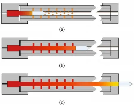
Fig.3.Schematic of the launching process: (a) First stage; (b) Second stage; (c) Third stage.
The internal ballistics process of the launching system of auxiliary charge with filter cartridge structure can be divided into three stages,and each stage is analyzed below.In the first stage,the internal ballistic process is consistent with traditional artillery, as shown in Fig.3(a).The primer is first ignited, and then the breech charge is ignited.The projectile starts to move when the gas pressure exceeds the critical pressure of the diaphragm.In the second stage, the high-temperature,high-pressure gas trailing the projectile passes through the filter cartridge auxiliary chambers when the projectile moves toward the mouths of the auxiliary chambers, and then the filter cartridge auxiliary charges are ignited,as shown in Fig.3(b).The last stage begins with the end of the complete combustion of the auxiliary chamber charge and ends with the projectile leaving the gun barrel,and the primary process of the interior ballistic process has been finished,which is shown in Fig.3(c).
2.2.Conditions of experiments
In this paper, the charge was composed of two parts.The part placed in the breech was fabricated from grains of a cylindrical single-base propellant with a diameter of 2.2 mm and a length of 2.8 mm and had a loose-packed density.The auxiliary charge was composed of a nineteen-perforated single-base propellant with a side length of 2.88 mm and a length of 7 mm, and the web andperforation diameters were 0.78 mm and 0.18 mm, respectively.Moreover, each hole is filled with a 19-perforated propellant particle in the auxiliary charge with a filter cartridge structure.In the experiment, the mass of the breech charge was 18 g.The filter cartridge auxiliary charge mass varied from 0 g up to 60 g in firings with the 67-g projectile.As an important part of the launcher, the thickness of the diaphragm has an important effect on the reaction of propellant in the chamber.Therefore,to analyze the influence of propellant reaction degree in the chamber on the internal ballistic performance,0,1,and 2 mm diaphragms were respectively studied in the experiment.With the increase of the length of the charge,the pressure impulse will have a limited ability to do work on the projectile within the limited length of the barrel.Therefore, the barrel length is studied in the experiment.The type of projectile used in the experiment is pointed, and the material is 35CrMnSiA.The material of the diaphragm is 1060Al.The specific ignition conditions are shown in Table 2.It is worth noting that in each experiment, only the corresponding variables were changed, and other parameters were unchanged.

Table 2Conditions of firings were conducted with a 67-g projectile in the 16-mm laboratory barrel setup.

Fig.4.Schematic of the instrumentation and control system.
Firing experiments of the filter cartridge auxiliary charge were conducted in a test launch system with a 16 mm smoothbore barrel.The schematic of the auxiliary launching system with the filter cartridge structure is shown in Fig.4, which includes three main parts: the pressure measurement system, the velocity-measuring system, and a propelling setup.The pressure measurement system consists of a pressure transducer, a charge amplifier, an oscilloscope, and a computer.The pressure sensor adopts a quartz pressure transducer produced by PCB Piezotronics, Inc.(Walden Avenue,Depew,NY14043 USA)that is piezoelectric for the need for dynamic pressure.During the tests, the pressure is converted into charge value under the positive piezoelectric effect, and then the voltage signal is transmitted to the transient data collector via a charge amplifier.Finally, the input signal is processed by a computer to obtain a pressure-time curve.The velocity-measuring system includes aluminum foil targets and a high-resolution electric timer.For the velocity-measuring system, muzzle velocity values are measured from time intervals for each projectile to pass through aluminum foil targets placed at known distances apart.Talley[34]reported the muzzle velocity of the projectile measured with aluminum foil targets was considered to be more accurate than the velocity measured with the interferometer.

Fig.5.Time histories of pressure in the breech chamber without diaphragm.
3.Result and discussion
3.1.Length of auxiliary charge
At first, the effect of the filter cartridge auxiliary charge length on the muzzle velocity of the projectile and the pressure of the breech chamber is discussed.The detailed development of the breech chamber pressure during the launch process comparisons of the projectile motion between the traditional gun and guns with the filter cartridge auxiliary charge is clearly shown in Fig.5,and all experimental results can be obtained by processing the pressuretime history curve, as listed in Table 2.Figs.6 and 7 show the velocity and the area of the pressure curve for different charge lengths, respectively.
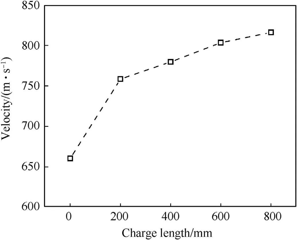
Fig.6.Muzzle velocity at different charge lengths.
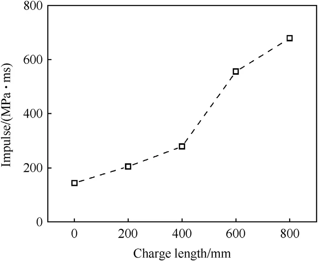
Fig.7.Impulse at different charge lengths.

Fig.8.Time histories of pressure in the breech chamber at different charge qualities.(a) 0 g; (b) 15 g; (c) 30 g; (d) 45 g; (e) 60 g.
As shown in Fig.5,the shape of the pressure-time history curve of T-1 resembles a parabola, which is the inherent form of the pressure change in the traditional artillery chamber.As shown in the pressure-time curve shown at T-2 to T-5,the pressure change in the gun is the same as that of traditional guns in the initial stage of artillery firing.That is, the pressure in the chamber first increases and then decreases.Subsequently,the pressure drop becomes slow in the breech chamber.Obviously, this is the result of the effect of the filter cartridge auxiliary charge.It shows that the auxiliary charges are ignited by the high-temperature, high-pressure gas trailing the projectile.The gas from the combustion of the propellant in the auxiliary chambers enters the gun barrel, which compensates for the pressure drop caused by the movement of the projectile, maintaining a constant pressure at the bottom of the projectile until the propellant burns out.As a result, the breech pressure and the muzzle velocity of the projectile are increased,as shown in Figs.5 and 6.
Furthermore,in Fig.5,with the length of the charge increasing,the pressure curve of the novel launching device gradually becomes flat, and even a pressure platform or secondary peak pressure is formed in the barrel.Considering the particularity of the launch barrel, in order to ensure the launching safety and tactical requirement, platform pressure must be lower than the peak pressure.It can be seen from Fig.5 that the peak pressure in the breech chamber remains basically unchanged with the length of the auxiliary charge increasing.Moreover, the secondary peak pressure is about 90 MPa,which is less than the peak pressure.It is evident that it meets the requirements of the design.In addition,compared with traditional artillery, the maximum velocity of the filter cartridge structure auxiliary charge launching device can reach 816.06 m/s, which increases by 23.57%, as shown in Fig.6.Moreover, it can be clearly seen in Fig.7 that the area of the pressure curve for the novel launching device is more significant than that for the traditional artillery firing test device.Hence, the propellant of the novel launching device does more work on the projectile, and it is understandable that the muzzle velocity of the projectile is very high.
3.2.Influence of the degree of propellant reaction in the breech chamber
The degree of reaction of the propellant in the breech chamber is an essential factor affecting the launching system of auxiliary charge with filter cartridge structure.Moreover, in order to investigate the influences of the reaction degree of propellant in the chamber on the performance of the gun, the experiment used diaphragms with different thicknesses to simulate the change of the chamber pressure during the firing process of the gun.Fig.8 compares the time histories of the breech pressure chamber at different thicknesses of the diaphragm, respectively.Fig.9-11 compare the muzzle velocity of the projectile, peak pressure, and impulse at different diaphragm thicknesses, respectively.
The rupture pressure of the diaphragm can control the start time of the projectile and influence the maximum peak pressure in the breech chamber[35].At the same time,the rupture pressure of the diaphragm is equivalent to the extrusion pressure of the projectile in the gun.Therefore, this section essentially studies the effect of starting pressure on the projectile.As shown in Figs.8 and 10, the higher the peak pressure in the breech chamber with the thickness of the diaphragm increases.That is precisely what this experiment aims to achieve.It is understandable that the higher the initial acceleration obtained by the projectile.Therefore, under the same charge condition,the thicker the diaphragm,the muzzle velocity of the projectile is higher, as shown in Fig.9.It can be clearly found that with the increase of the charge length, the projectile velocity increases by 23.57%, 14.64%, and 7.65%, respectively, during the firing process of the artillery under different diaphragm thicknesses.However, the muzzle velocity of the projectile did not change significantly when the charge length reached 800 mm.In addition, according to Fig.8, no matter how the thickness of the diaphragm changes, a stable pressure platform will be formed in the chamber as the length of the charge increase.Furthermore,the duration of the pressure platforms is 3.40, 2.85, and 2.33 ms,respectively.It is evident that the durations of pressure platforms decrease slightly with the increase of diaphragm thickness.
On the one hand,a higher breech chamber pressure is obtained by the thick diaphragm, which increases the starting pressure of the projectile.The initial acceleration of the projectile is high.The initial velocity of the projectile is higher relative to the thin diaphragm so that the time for the projectile to travel within the same length of the barrel is reduced.On the other hand,with the increase of the length of the charge, the area of the pressure curve in the barrel gradually tends to be consistent during the projectile launching process under different thickness diaphragms,as shown in Fig.11.Therefore,under the diaphragm of different thickness,the gas pressure in the barrel does basically the same work on the projectile.As a result, the duration of the pressure plateau in the chamber becomes shorter with the thickness of the diaphragm increases.This is also the reason why the muzzle velocity of the projectile does not increase significantly during the firing of the artillery with the thicker diaphragm.
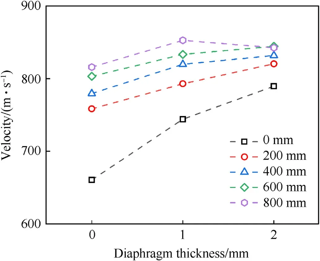
Fig.9.Muzzle velocity at different diaphragm thickness.
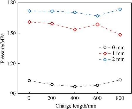
Fig.10.Peak pressure at different diaphragm thickness.
3.3.Length of the barrel
The study found that the increment of the muzzle velocity of the projectile is smaller with the increase of the reaction degree of the propellant in the chamber.For example, in the experiment with a 2 mm thick diaphragm, the muzzle velocity of the projectile was only increased by 7.56%.It is found that the starting pressure of the projectile increases,resulting in the reduction of the effective time of the gas generated by the combustion of the propellant on the projectile.Further, although the peak pressure in the breech chamber is increased, the work done by the gas on the projectile does not change much during the projectile launch.It is understandable that the gas generated by the combustion of the auxiliary charge leaks into the air and cannot be applied to the projectile when it is fired with a thicker diaphragm.Therefore, in order to study the energy dissipation during projectile launch under a 2 mm thick diaphragm, it is indispensable to lengthen the barrel.According to the laboratory conditions, we doubled the length of the barrel on the original basis.

Fig.11.Impulse at different diaphragm thickness.
Fig.12 compares the time histories of the breech chamber at different barrel lengths, respectively.It is worth noting that the peak pressure of the breech remains basically unchanged, regardless of whether the length of the gun barrel and the auxiliary charge change when the mass of the propellant in the chamber remains unchanged.In addition, according to the experimental results,compared with the launch of the 2 m barrel under the same conditions, the muzzle velocity increment is 113.13 m/s, which increased by 13.42%.Under the same conditions,with the increase of barrel length, the energy utilization rate of propellant increases by 28.64%.Hence,increasing the length of the barrel can effectively improve the performance of the filter cartridge structure auxiliary chamber launch system.
4.Conclusions
In this study,a launching system of auxiliary charge with a filter cartridge structure was proposed, which improves the muzzle velocity of the projectile.In order to obtain some internal ballistic characteristics of the novel launch system,firing experiments of the filter cartridge auxiliary charge were conducted in a test launch system with a 16-mm smoothbore barrel.Cylindrical single-base propellant particles are used as the breech chamber charge, and single-base propellant gains with nineteen perforations are used as the auxiliary charge.The pressure of the breech chamber was measured by a pressure transducer,and the muzzle velocity of the projectile was measured by foil targets.The main conclusions of the study are as follows.
(1) The internal ballistics are stable as the device operates.Moreover,the experimental results verified that the working principle of the launching system of auxiliary charge with filter cartridge structure includes three stages.The first stage involves the breech chamber operating on its own, the second stage involves the main chamber and auxiliary chambers operating collaboratively, and the third stage involves the free expansion of the gas produced by the combustion of the propellant.
(2) Compared to traditional artillery,a higher muzzle velocity is obtained while maintaining the same peak pressure as that of a conventional charge.
(3) The new launch system changes the pressure distribution characteristics of the space behind the projectile, and the filter cartridge structure auxiliary charge the combustion of the propellant to make up for the pressure drop caused by the projectile movement in the traditional launching method.The test results show that with the increase of the auxiliary charge length of the filter cartridge structure, a stable pressure platform can be formed in the barrel,which is less than the peak pressure in the barrel.
(4) The higher degree of propellant reaction, the higher muzzle velocity, and the higher breech pressure are formed by a thicker diaphragm.Increasing the barrel length can improve the performance of the launching system of auxiliary charge with filter cartridge structure,allowing the gas generated by the combustion of the propellant to do more work on the projectile.
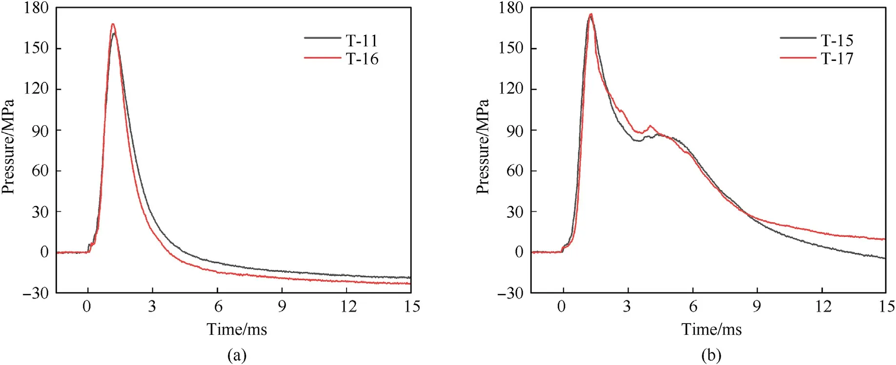
Fig.12.Time histories of pressure in the breech chamber at different charge qualities: (a) 0 g; (b) 60 g.
Declaration of competing interest
The authors declare that they have no known competing financial interests or personal relationships that could have appeared to influence the work reported in this paper.
Acknowledgements
This research was financially supported by the National Natural Science Foundation of China under Project No.51874267 and No.12272374, the Fundamental Research Funds for the Central Universities under Project Nos.WK2480000008,WK2480000007,and WK2320000049.The authors would like to thank these foundations for financial support.
- Defence Technology的其它文章
- The interaction between a shaped charge jet and a single moving plate
- Machine learning for predicting the outcome of terminal ballistics events
- Fabrication and characterization of multi-scale coated boron powders with improved combustion performance: A brief review
- Dependence of impact regime boundaries on the initial temperatures of projectiles and targets
- Experimental and numerical study of hypervelocity impact damage on composite overwrapped pressure vessels
- On the effect of pitch and yaw angles in oblique impacts of smallcaliber projectiles

