
Experimental and numerical study of hypervelocity impact damage on composite overwrapped pressure vessels
2024-02-29 08:21YongPnDunRunQingChiBoJunPngYunCi
Defence Technology 2024年1期
Yong-Pn Dun , Run-Qing Chi ,*, Bo-Jun Png , Yun Ci
a Hypervelocity Impact Research Center, Harbin Institute of Technology, Harbin,150080, China
b College of Science, Heilongjiang University of Science and Technology, Harbin 150022, China
Keywords: Orbital debris Hypervelocity impact Composite overwrapped pressure vessels Damage mechanisms
ABSTRACT Ground-based tests are important for studying hypervelocity impact(HVI)damage to spacecraft pressure vessels in the orbital debris environment.We analyzed the damage to composite overwrapped pressure vessels (COPVs) in the HVI tests and classified the damage into non-catastrophic damage and catastrophic damage.We proposed a numerical simulation method to further study non-catastrophic damage and revealed the characteristics and mechanisms of non-catastrophic damage affected by impact conditions and internal pressures.The fragments of the catastrophically damaged COPVs were collected after the tests.The crack distribution and propagation process of the catastrophic ruptures of the COPVs were analyzed.Our findings contribute to understanding the damage characteristics and mechanisms of COPVs by HVIs.
1.Introduction
Orbital debris is any man-made object in orbit around the Earth that no longer serves a useful function,which is defined in Ref.[1].With the increasing frequency of human space activities,increasing attention has been paid to the risks arising from orbital debris to spacecraft components.Gas-filled pressure vessels are often employed to contain gases, such as breathing gases and pressurizing gases.In particular, carbon-fiber composite overwrapped pressure vessels (COPVs) are widely used in spacecraft systems.Due to the high specific strength of composites,COPVs are smaller in mass than metal vessels [2].The COPVs installed outside spacecraft structures are exposed directly to the orbital debris environment.They may fail catastrophically when impacted because of the energy stored within them.Despite limited knowledge of the failure mechanisms of COPVs,two typical COPV failure modes have been noted: simple perforations and catastrophic ruptures [3].
In the past decades, damage to metal pressure vessels by HVIs has been widely studied.The scholars have studied cratering and perforations of front walls [4-6], gas shock waves and secondary debris clouds [7-12], and the burst limit conditions [13-15].Unfortunately, studies on HVIs on COPVs are still lacking.In terms of experimental research, various types of damage to COPVs by HVIs have been simulated in the laboratory[3,16].However,the damage mechanisms have been rarely analyzed elaborately.Numerical modeling has been relatively limited.Garcia M A studied the cratering and perforations caused by HVIs on COPVs without internal pressures [3].Hereil P L and Maveyraud C numerically simulated the secondary debris cloud, the gas shock wave and the overall damage to pressure vessels caused by HVIs [16,17].Cherniaev A studied the damage characteristics of filament-wound composites by HVIs through numerical simulation [18,19].Schonberg developed a series of ballistic/rupture limit equations based on test data,which can be used to predict whether a COPV is perforated/ruptured when impacted[20-22].However,there is no systematic research specific to damage characteristics and mechanisms to COPVs by HVIs in the literature.
Our work focused on damage characteristics and behaviors of COPVs by HVIs.Millimeter-sized aluminum alloy projectiles were accelerated to several kilometers per second by a two-stage light gas gun to simulate the impact of orbital debris during the operation of COPVs.The results showed that the damage was divided into two types:non-catastrophic and catastrophic damage.The rupture of the COPV is defined as catastrophic damage in this paper,and the simple perforation is non-catastrophic damage.Due to the limited test data, we proposed a numerical simulation method to further study non-catastrophic damage.The damage morphologies,perforation sizes and stresses at the perforation edges of noncatastrophic damage were studied through numerical simulation.It should be noted that the non-catastrophic damage of the rear walls of COPVs is not concerned in this paper,and the walls refer to front walls when not specifically stated in the paper.In addition,the characteristics and process of catastrophic damage were determined by analyzing the fracture fragments recovered after the tests.
2.Experiment
2.1.Test targets: COPVs
A COPV comprises a metallic liner made of AL6061-T6 and reinforced by a carbon-fiber-reinforced plastic(CFRP)overwrap,as shown in Fig.1.The CFRP layer is wrapped on the liner by filament winding technology, and two winding patterns, including helical winding (winding angle β= 18.4°) and hoop winding (winding angle β=90°),are used for the COPV.Since the closed structure of the liner is formed by welding,two circumferential weld joints and one axial weld joint are on the liner.The outer diameter of the liner is around 190 mm,and its length is 310 mm.The COPVs with high and low thicknesses of CFRP layers(HTC and LTC)were considered.The thicknesses of the liner and CFRP layer are larger in the dome region and smaller in the cylindrical region.In the cylindrical region, the thickness of the liner is around 1.00 mm, and the thicknesses of HTC and LTC are around 1.55 mm and 0.72 mm,respectively.More details about the structure of COPVs, such as winding angles and the winding sequence, are shown in Fig.1.
The designed bursting pressures of the two types of COPVs are 24.2 MPa(HTC) and 10.8 MPa(LTC), respectively.These values are only based on the maximum tensile strength of composite materials in COPVs.Considering the safety factor of 1.4, the maximum allowable working pressures are 17.3 MPa(HTC)and 7.7 MPa(LTC),respectively.In the cylindrical region of the COPV, the circumferential strength is about 1.89 times (HTC) and 1.69 times (LTC) the axial strength.However,in each COPV,the circumferential load on the COPV wall during operation is twice that of the axial load.Thus,the ratio of the circumferential load to the strength is higher,meaning that the circumferential bearing capacity of each COPV is smaller.
2.2.Experimental process

Fig.1.Structure of COPVs.
Hypervelocity tests were performed at Hypervelocity Impact Research Center, Harbin Institute of Technology.We used a twostage light gas gun to launch spherical projectiles to impact the non-weld joint areas of COPVs to avoid the influence of weld joints on initial damage.The projectiles are 6.35 mm or 4.76 mm in diameter and made of Al 2017-T4.To ensure safety and collect postburst fragments, we installed the COPVs in a container made of high-strength steel.A hole is in the front of the container, and projectiles can pass the hole to impact the COPVs.The high-density ethylene-vinyl acetate (EVA) foam with a thickness of 20 mm was placed against the inner surface of the container to collect fragments.The impact velocity was measured using a magnetic induction speed measuring device.Nitrogen was filled into the COPVs before impact.The experimental process is shown in Fig.2.A series of five normal impact tests were performed on COPVs.The internal pressure values selected are broadly representative of the load levels during the operation of the spacecraft COPVs, based on our experience,allowing the vessel to occur as many damage modes as possible.The parameters and preliminary results of all tests are shown in Table 1.
2.3.Experimental results
All test results are shown in Table 1.Five post-test photographs of COPVs damaged by HVIs are shown in Fig.3.Two typical COPV damage modes, including perforations (Figs.3(a)-3(c)) and ruptures(Figs.3(d)and 3(e)),can be found in these images.In the case of perforation,severed torn CFRP fibers,ply delamination and liner perforations of the front walls commonly occurred.Both the front and rear walls were perforated in TEST-9,while only the front wall was perforated in TEST-1 and TEST-4.The local features of the front wall perforations are magnified at the upper left of the images,and those of the rear wall perforations are magnified at the bottom right.Further more,a further enlarged image of the perforation in TEST-1 are shown in Fig.3(f).The COPVs with LTCs ruptured when pressure was relatively high, i.e.in TEST6 and TEST8,see Figs.3(d)and 3(e).In the case of rupture,the dome regions of the COPVs were separated,and the cylindrical regions were severely disintegrated.
3.Numerical modeling for studying non-catastrophic damage
Hypervelocity impact processes are violent and complex,especially when energy storage targets, such as COPVs, are involved, and the details are difficult to measure accurately using experimental methods.In addition, data obtained from experiments are often valuable and scarce because they involve many factors, such as safety, economy and efficiency.Numerical simulation is a relatively economical and efficient supplement which can clearly show the details of the impact event, such as stresses and morphologies.Therefore,a series of numerical simulations are used to study the non-catastrophic damage of COPVs by HVIs.All simulations presented in this paper were carried out using LS-DYNA-3D hydrocode, which is suitable for modeling HVI events.
Fig.2.Schematic of the experimental process.

Table 1Parameters and results of all the tests.
3.1.Numerical modeling
Lagrangian meshes are embedded in the material and move and distort with it.They can track material interfaces effectively and describe material behavior clearly.Therefore, they are suitable for simulating perforations caused by HVI.However, when dealing with HVI events, mesh distortions and tangling occur.Erosion algorithms can solve the above problems by removing the finite elements of geometric strains to user-specified values and are usually combined with Lagrangian meshes.
The finite element model includes a cylindrical COPV and a spherical projectile.Two types of COPVs were modeled to correspond to the COPVs with HTCs and LTCs in the experiment.The winding structure can be treated as a homogeneous laminate because the width of the single filament band is much larger than its thickness (about 30-70 times).In addition, it is usually appropriate to integrate the adjacent layers if they are oriented in the same direction, which can greatly improve the computational efficiency by increasing the element size in the thickness direction.Due to the symmetry of the COPV,we built a semi-geometric model(the symmetry plane passes through the center of the cylinder and is perpendicular to the ballistic direction) and entirely created a spherical projectile.Although the computational efficiency can be improved, the above symmetric model has the following defects:(1)when the stress wave generated by the impact propagates to the symmetry plane along the COPV wall, it is reflected at the symmetry plane,propagates away from the symmetry plane,and finally converges at the impact site;(2)the helical winding filament band are not strictly symmetrical due to the non-zero winding angles.The errors caused by the above defects are acceptable when the research scope is strictly limited to the characteristics of the local impact regions in the model, because the symmetry plane is far from the impact position,and the winding angle of helical winding filaments is small.In this study, the dome region of the COPV was not considered because the complicated winding pattern of the dome region could cause great difficulties to finite element modeling.Fully integrated hexahedral solid elements were used in current work, with in-plane elements dimensions of 1.5 mm×1.5 mm and the dimension in the thickness direction is about 0.15 mm.The mesh around the impact region (approx.25 mm×25 mm)was additionally encrypted,with a dimension of about 0.15 mm×0.15 mm×0.15 mm.The finite element model of the projectile and COPV with the LTC is shown in Fig.4.

Fig.3.Post-test photographs of COPVs: (a) TEST-1; (b) TEST-4; (c) TEST-9; (d) TEST-6; (e) TEST-8; (f) Enlarged view of the perforation in the front wall of the COPV in Test-1.
Fig.4.The finite element model.
Axial and circumferential tensile membrane stresses can be generated in the cylindrical region of the actual COPV wall,which is caused by the internal pressure acting on the COPV wall.However,building a 3D gas model inside a COPV is very difficult because dramatic computational resources are required.Representing the action of the pressurized gas on the COPV wall through a set of boundary conditions is feasible and effective and can considerably reduce the computational time.The stress distribution in each layer of the COPV is complex.For example, the hoop winding filament layers bear most of the circumferential tensile membrane stress.One of the difficulties of simulation is how to apply boundary conditions to make the stress distribution in each layer as close to the real situation as possible.The circumferential tensile membrane stress can be naturally loaded using pressure boundary conditions the same as the actual internal pressure conditions on the inner surface of the COPV.For axial tensile stress,displacement boundary conditions are applied slowly at both ends of the cylinder.This approach is based on the important premise that there is no relative sliding between layers during pressurization.The premise is actually reasonable because of the geometric symmetry of the cylindrical COPV.We proposed a two-step procedure suitable for determining the values of displacement boundary conditions and applying biaxial stresses in this paper (Fig.5).The steps are as follows:
(1) A test model was built.In this model,the fiber orientations of all composites were perpendicular to those of the actual COPV wall within their respective layers.In addition, a pressure boundary condition was applied on the inner surface of the COPV wall,with a value of half the actual internal pressure.In fact, since the circumferential stress-bearing structure of the COPV wall in the test model was the same as the axial stress-bearing structure of the actual COPV wall(the curvature was ignored),the circumferential stress in the test model was equal to the axial stress() of the actual COPV wall.The distribution of circumferential stress()in each layer CFRP was monitored.
Fig.5.Method of applying biaxial stresses.
(2) A valid model was built in which the fiber orientations of all composite layers were the same as those of the actual COPV applied in the experiment.A pressure boundary condition the same as the actual internal pressure condition was applied to the inner side of the COPV wall to generate circumferential stress.Displacement boundary conditions were then applied slowly at both ends of the cylinder so that the generated axial stress of each layer was approximately equal to the circumferential stress in the test model(in Step 1).
The above boundary conditions were slowly applied by an explicit program in LS-DYNA, and global damping was applied through the *GLOBLE_DAMPING keyword so that the stresses reached a steady state.When the velocities of all elements in the model were close to zero,the global damping was removed,and the transient analysis was performed on the HVI.
In the simulation,the Gruneisen equation of state,the Johnson-Cook strength equation and the maximum tensile stress failure criterion were selected to describe Al 2017-T4 (material of the projectile) and Al 6061-T6 (material of the liner), while the orthotropic elastic model was used to describe CFRP.The material parameters of Al 2017-T4 and Al 6061-T6 can be referred to Ref.[23].The material parameters of CFRP in Ref.[18] were modified adaptively due to the difference in fiber volume fraction (60% in this paper).However, in the previous numerical simulation, it was found that the inner and outer flanging would occur in the edge of the liner perforation, rather than the inward bending as in the experiment, suggesting that the CFRP thickness directional impedance was severely underestimated in this numerical approach.In the process of winding,the resin in the filament band is compressed,and its modulus in the thickness direction should be far greater than the initial transverse modulus of the filament band,especially under pressure.Another possible reason is that the erosion algorithm removes some distortion elements,which affects the subsequent deformation process of the COPV wall.Therefore,the impedance of CFRP was increased by enhancing the stiffness in the direction of CFRP thickness to make up for the above defects,enabling the simulation results to be more consistent with the test results (see Section 3.2).It should be noted that the modified material parameters are only applicable to the finite element numerical simulation for the hypervelocity impact problems.A set of fracture criteria were used to describe the failure of interlaminar cohesion: tensile strength and shear strength were set to 83 MPa and 48 MPa, respectively.The material parameters of CFRP in this paper are shown in Table 2.
3.2.Validation of numerical simulation
The numerical models developed in subsection 3.1 need to be validated before being used in research.We analyzed the strengths and weaknesses of the model from both qualitative and quantitative aspects.
The regions around the perforations of the recovered COPVs after the experiments were cut,and the CFRP layers were carefully secured with tape.The experimental and numerical morphology characteristics of the cross-sections of the perforations are shown in Fig.6.With the consideration of the calculation costs,it is almost impossible to stop the numerical simulation until the velocities of all elements are 0.Therefore, unless otherwise specified, the numerical simulation results in this paper refer to the results at the moment of 25 μs after the impact because the shapes of the COPV walls are roughly stable, and no plastic deformation continues to occur at this time.The experimental and numerical morphologies show that the aluminum alloy liners were bent inward, and the CFRP layers were severely delaminated.However, it should not be ignored that the bending degree of liners is overestimated in numerical simulation,which may be due to the description method of gas action, the applicability of the material model to HVIs, incomplete recovering of the elastic deformation in the short time of numerical simulation or the limitation of the Lagrange erosion algorithm.Although the model needs to be improved, this evidence indicated that the numerical model could represent experimentally observed phenomena in a qualitative manner.
We quantitatively assessed the accuracy of the model by comparing the numerially predicted and experimentally determined diameters of the perforations.The experimental and numerical diameters of the perforations are shown in Table 3.A good correlation(within about 8.7%)is found between the numerical and experimental results of liner perforations.However,the prediction of CFRP perforation by numerical simulation shows a large error(within about 42.1%)compared with the experimental results.The numerical simulation generally underestimates the perforation sizes, and the maximum error occurs in TEST 1.In fact, the perforation edge morphology of CFRP is very complex, the final perforation radiusr2is not directly generated by the initial impact, but there is a subsequent perforation expansion process as shown in Fig.3(f).We preliminarily infered that due to the brittleness of CFRP, the erosion algorithm prematurely deleted some severely deformed elements,resulting in the deletion of the elements in theCFRP central area that were initially impacted,and the subsequent perforation expansion process cannot continue.Therefore, discussion on the CFRP perforation size is avoided in this paper.

Table 2Properties of CFRP.
Fig.6.Comparison of experimental and numerical perforation morphologies.

Table 3Comparison of numerical and experimental results.
4.Numerical analysis of non-catastrophic damage
The non-catastrophic damage to COPVs by HVIs was studied using the validated numerical models introduced in Section 3.In the simulation,in addition to the 3 conditions(TEST-1,TEST-4 and TEST-9) that were the same as the experimental conditions, 26 cases were implemented to study the influence of internal pressure and impact velocities on non-catastrophic damage to COPVs.The impact velocity of projectiles were 4.50 km/s and 7.50 km/s,with a diameter of 6.35 mm.The internal pressure in the COPVs ranged from 0-9.6 MPa and 0-5.0 MPa, respectively, corresponding to COPVs with HTCs and LTCs.
4.1.Damage morphologies of the COPV front walls
The non-catastrophic damage morphology of the COPVs in the numerical simulation in the 26 cases is shown in.Fig.7.Two typical morphology features were found,delamination and bending of the liner material around the perforation.
Delamination was found between a pair of CFRP layers and between the CFRP layer and the liner in all cases.The stress wave generated by the impact event propagates along the fiber orientation in the CFRP layer.Therefore, if neighboring layers have dissimilar orientations (e.g., 90°and 18.4°), such loading causes local (along the wave path) interfacial shearing and may result in localized delamination[18].Surface ply-peeling was found around the perforations in the experimental results (Figs.3(a)-3(c)), and the surface ply-peeling became more severe as the pressure increased.After the outermost hoop winding CFRP layers were penetrated, their restraint around the perforations was lost, the initial pre-stress in the local CFRP layers was released, and the elastic deformation of the CFRP layers tended to recover.This phenomenon meant that the initial pre-stress within the COPV walls facilitated the propagation of the delamination.In addition,the propagation of rarefaction waves along the thickness direction caused by the reflection of stress waves from the free surface and adjacent interlayer interfaces around the impact region may also contribute to the delamination around the impact region.
In all cases, both the liners and the CFRP were penetrated and the materials near the perforations of the liners were bent inward,as shown in Figs.7(a)-7(d).These morphologies can be explained by the behavior of stress waves.The stress wave generated by the impact event propagated to the inner surface of the COPV.Since the inner surface of the COPV was a free surface, a rarefaction wave could be reflected from this surface and propagate to the outside of the COPV along the thickness direction.A gap was created at the interface between the liner and the CFRP layer due to the stretching action of the rarefaction wave.Thus,the rarefaction wave could not continue to propagate to the CFRP layer, causing the liner to bend toward the inside of the COPV.Fig.8 shows the aforementioned deformation mechanisms of COPV walls around the perforation.
Fig.7.Numerical perforation morphologies: (a) V0 = 4.5 km/s, HTC; (b) V0 = 7.5 km/s, HTC; (c) V0 = 4.5 km/s, LTC; (d) V0 = 7.5 km/s, LTC.
Fig.8.Diagrams of the deformation mechanisms of the COPV front wall.
With the increase in the impact velocity, the amplitude of the rarefaction wave increased, but the interaction time between the projectile and the COPV wall decreased.More impact energy was transferred to the debris cloud, with only a very small amount remaining inside the COPV wall,as shown in Fig.9.The drop in the curve was caused by the erosion of severely deformed elements that roughly represent the debris cloud.Therefore, when the impact velocity was 4.5 km/s, the liner bent inward seriously.However, when the impact velocity increased to 7.5 km/s, the curvature of the liner bending decreased.Similarly, a smaller thickness of the COPV wall reduced the interaction time between the projectile and the COPV wall,reducing the curvature of the liner bending.
In order to investigate the influence of internal pressure on the COPV wall damage morphology, we defined a dimensionless parameter Δs to evaluate the curvature of the liner bending.
Fig.9.Energy variation curves of the liners.
wheres(P0) is the axial displacement of the liner feature point when internal pressure isP0, ands(0) is the axial displacement of the liner feature point when internal pressure is 0.The liner feature point is defined as the junction point of the impact axis offsethand the inner edge of the liner,wherehis chosen to be 12 mm,as shown in Fig.10.
Fig.10.Diagram of the liner feature point.
Fig.11.Effects of internal pressure on Δs.
The effects of internal pressure on Δs in different types of damage morphologies are shown in Fig.11.In all cases,Δs decreases linearly with the increase in internal pressure, and the R square is greater than 0.94.The above results indicated that the internal pressure obstructed the movement of the liners.Further more,with the impact velocity increases and/or the COPV wall thickness decreases,the absolute value of the slope of the curve increases.These results can be explained by a competing set of factors acting on the COPV wall,i.e.,the transfer of the impact energy to the COPV wall can cause plastic deformation of the liner, while the internal pressure can obstruct deformation.In the numerical model in the present work, the internal pressure was represented by constant pressure boundary conditions.When the impact velocity was relatively high, and/or the COPV wall thickness was small, the interaction time between the projectile and the COPV wall was relatively short.The residual energy of the HVI obtained by the liner in this case was smaller, meaning that the action of internal pressure relatively enhanced.
4.2.Liner perforation sizes of the COPV front walls
The gas leakage rate is often related to the liner perforation sizes, thus the liner perforation diameters in the simulation were carefully measured for all cases and the results are shown in Fig.12.From Fig.12, we can identify a number of general trends in perforation sizes of the COPV walls and make some quantitative observations.

Fig.12.Statistics of the perforation diameters.
(1) It is showed that the perforation size of the liner decreases with increasing impact velocity for the COPV with HTC,while for the COPV with LTC,the opposite is true,within the scope of this study.As the impact velocity increases, two phenomena occur that effect the perforation size of the liner:a)the intensity of the shock wave increases;b)The interaction time between the projectiles and the COPV walls decreases.The mentioned phenomena have competing effects on the perforation size.While the degree of the material crushing and plastic deformation is increased with an increase in the intensity of the shock wave, the accompanying decrease in the interaction time between the projectiles and the COPV walls must also be considered.As the interaction time between the projectiles decreases,the energy transferred to the COPV walls decrease as well,resulting in the reduction of the curvature of the perforated edge material and the perforation size.It is obvious that the main influence mechanism of impact velocity on perforation size is different for COPVs with different thicknesses.
(2) The perforation sizes of the walls of COPVs with HTCs are larger than those of COPVs with LTCs at the same impact velocity in all cases.This is due to the longer interaction time between the projectiles and the thicker COPV walls,resulting in more severe crushing and plastic deformation of the materials in the impact regions.
(3) In all cases,the perforation sizes of the COPV walls decreased slightly as the internal pressure increased.This may be explained by the effects of internal pressure on the structural deformation of the materials near the perforations as mentioned in subsection 4.1.With the increase in internal pressure, the structural deformation near the liner perforations decreased, actually reducing the perforation sizes.In addition, as internal pressure increased, the thicknesses of the COPV walls gradually decreased under the action of internal pressure, which may also contribute to the reduction in the perforation size.
Some measurement errors are inevitable for the perforation sizes in this paper due to the irregular morphologies of some perforation edges.Even so, the trends and mechanisms of the effects of the COPV wall thickness, impact velocity and internal pressure on perforation sizes are revealed.Moreover,we found that the effect of internal pressure on perforation size is much smaller than that of the COPV wall thickness and impact velocity through the current observations.
4.3.Stresses at the perforation edges
For metal pressure vessels, the theory of linear elastic or elastoplastic fracture mechanics is used to predict whether the cracks at the perforation edges will spread unstably and cause COPVs to burst.However, for complex structures such as COPV walls, no relevant theoretical studies have been found.
Although the burst limit conditions of COPV walls cannot be calculated theoretically, and there are not enough experimental data to fit an empirical prediction equation, some trends can be identified in the current work.The dominating pressure-bearing structure of a COPV is CFRP layers, and the circumferential bearing capacity of a COPV is relatively small.Therefore, the stresses at the hole edge of the hoop winding CFRP are concerned in this work.Taking the example of a 6.35-mm projectile impacting a COPV with the LTC at 7.5 km/s with a pressure of the COPV of 5.0 MPa, the circumferential (the same direction as the fiber orientation in hoop winding CFRP) stress σedgeat the perforation edge(Region 1 in Fig.13)was monitored.Two typical stages of σedgeafter the impact are shown in Fig.14.The period from the impact of the projectile on the COPV wall to the arrival of the stress wave reflected from the symmetry plane at the impact region is defined as Stage 1.The period after the stress wave reflected from the symmetry plane reaches the impact region is defined as Stage 2.
In Stage 1,the impact of the projectile on the COPV wall leads to the perforation of the hoop winding CFRP, generating the initial stress wave with obvious directionality.The circumferential amplitude of the initial stress wave is much larger than its axial amplitude, which is determined by the fiber orientation.The compression wave is followed by the rarefaction wave reflected back from the free surface, as shown in Fig.13(a).The stress wave propagates along the COPV wall,and the velocity and amplitude of the circumferential propagation are greater than those of the axial propagation,as shown in Fig.13(b).The stress wave is reflected on the symmetry plane,and the generated reflected wave propagates to the impact region.The amplitude of the stress wave gradually attenuates during the entire propagation process.Before the reflected wave reaches the impact region, the σedgein the circumferential zone of the perforation tends to be zero (Region 2 in Fig.13(c)).There is stress concentration in the axial region(Region 1 in Fig.13(c)).The magnified history curve of the circumferential stress σedgeat the perforation edge(Region 1 in Fig.13)is shown in the upper right of Fig.14.In the first few microseconds, when the compression wave reaches this region, the σedgedecreases rapidly and then increases rapidly due to the reflected wave.With the propagation of the stress wave in the COPV wall,σedgeincreases first and then decreases.
In Stage 2, the reflected wave reaches the impact region and is superimposed onto another and then propagates towards the symmetry plane and attenuates.The stress wave is reflected on the symmetry plane, and the generated reflected wave propagates to the impact region.The above process is repeated, resulting in a distinct periodicity of σedge, as shown in Fig.14.After many cycles,the σedgecan reach a steady state, and the average value of the circumferential stress in the steady state is defined as σea.
However, the propagation behavior of the stress wave in this model is different from that in the actual case due to the influence of the symmetry plane.In an actual COPV, the stress wave can propagate to the rear wall, generate a superposition effect at the corresponding position on the rear wall,and continue to propagate to the impact region, repeating the cycle.It means that all the analysis involved in the first stage are available because the perforation edge stress is completely unaffected by the symmetric boundary conditions in the first stage.In this model, the σedgecontinues to decay and fluctuates around σea,the peak value of the circumferential stress σepat the perforation edge in Stage 1 is much larger than σea.Although we do not know the exact perforation edge stress of actual COPV in second stage,we can still make some qualitative analysis.As the stress wave continues to propagate,oscillates and attenuates repeatedly in the actual COPV,the stress at the perforation edge eventually fluctuates around the σea’.Due to the longer propagation distance and greater energy dissipation in the actual COPV, the σea’ will be lower than σeain the numerical model.Therefore σepis much larger than σea.It means that the method may seriously underestimate the results if σeais used in the theoretical analysis of crack instability propagation.
The influences of the impact velocity and initial internal pressure on the σepin Region 1 were investigated.We define two nondimensional parameters for uniform comparison.One is specific stress, defined as the ratio of σepto the tensile strength in hoop winding CFRP;the other is specific pressure,defined as the ratio of the initial internal pressure to the design burst pressure.Fig.15 shows the influence of the initial internal pressure on the σepat the gauge point in Region 1 at different impact velocities.Some qualitative trends can be found.
Fig.13.Pressure distribution in a hoop winding CFRP:(a)The initial perforation and stress waves are generated by the impact;(b)The stress waves propagate along the COPV wall;(c) The stress waves attenuate, and the stresses at the perforation edge gradually stabilize before the reflected wave reaches the impact region.
Fig.14.The circumferential stress curve of a gauge point in Region 1.
(1) For COPVs with LTCs, specific stress increases linearly with specific pressure and the R square is greater than 0.89.For COPVs with HTCs, specific stress still increases as specific pressure increases without a linear relationship and with a large degree of deviation, which may be related to the complex behavior of the stress waves caused by the complex perforation morphologies of COPVs with HTCs.

Fig.15.The stress level versus the pressure level at the gauge point in Region 1.
(2) Specific stress at an impact velocity of 7.5 km/s is higher than that at an impact velocity of 4.5 km/s due to a larger amplitude of the shock wave generated by a higher impact velocity.
(3) Specific stress in COPVs with HTCs is larger than that in COPVs with LTCs, which may be due to the thicker walls of COPVs of HTCs and longer interaction time between the projectiles and the COPV walls, resulting in a larger pulse width of the stress waves, which are not prone to attenuation.
In the above analyses of non-catastrophic damage to the COPV walls,we did not consider the effect of gas leakage.This is because the HVI process takes only several microseconds, while complete gas leakage takes a few tenths to a few seconds.Even if the morphologies, sizes and stress states of the COPV walls change after complete gas leakage,they are only caused by elastic deformation,and some qualitative trend analyses in this section are still valid.
5.Experimental results and analysis of catastrophic damage
5.1.Rupture limit condition
Whether the COPV ruptures depends on the thickness of each layer of the COPV wall, internal pressures, impact conditions and material properties of projectile and COPV.Schonberg [21] developed an empirical rupture limit equation (RLE) for predicting whether a COPV will rupture when impacted as
whereMprojis the non-dimensional projectile momentum,σhoop= P0rOD/ttotandare the COPV hoop stress and unidirectional ultimate stress of the COPV composite material,respectively;ttot=tcomp+tlineris the total nominal thickness of the cylindrical portion of the COPV, P0is the internal pressure in the COPV, and rODis the COPV outer radius, the A and B are both constants.
The non-dimensional form of projectile momentum was taken to be given as follows:
wheremprojis the mass of the projectile,is the normal component of the impact velocity,ρcompis the density of the CFRP,ρprojis the density of the projectile,andare the ultimate and yield stresses of the liner material,respectively,are in MPa,the exponentsQ,SandTare all constants.
According to Ref.[21],the values of the exponentsA,B,Q,SandTused in the non-dimensionalization scheme in Eqs.(1)and (2) are give as follows:A=2.166 ×10⁻³,B=-0.943,Q=0.1,S=-1.0,andT=-1.0.We compared the test data to this equation and found that the equation dramatically underestimated the COPV rupture limit,which predicted rupture in all cases in Table 1.
To make up this deficiency, Eq.(3) is modified as
The modified RLE compared to experimental rupture/nonrupture results are shown in Fig.16.The modified RLE accurately predicts whether the COPV will rupture.This study shows that the modified RLE performs very well under conditions similar,but not identical,to those Schonberg used to develop those equations,even though some oversight by the original authors may have caused the unit system or other problems.
Fig.16.Plots of Schonberg’s RLE curve and test data.
5.2.Catastrophic damage characteristics and mechanisms
In all the cases,no catastrophic ruptures occurred in the COPVs with HTCs due to low specific pressure, while when specific pressure was relatively high, catastrophic ruptures occurred in the COPVs with LTCs,such as TEST-6 and TEST-8.The original shapes of the fragments collected after COPV ruptures in TEST-6 and TEST-8 tests are shown in Fig.17, in which the fragments with an unfolded area of more than 4 cm2were cataloged.Most CFRP layers were broken into small fragments that are difficult to identify during the burst process due to the brittleness of CFRP,and only the dome region and Fragment 4 in TEST-8 remain relatively intact.The aluminum alloy liner is a ductile material, and the collected liner fragments have clear geometric profiles.We unfolded the collected aluminum alloy fragments and drew the diagrams of crack distribution in the liner by analyzing the geometry of the unfolded fragments.The left, front, right, and rear views are shown in Figs.17(c) and 17(d).It should be noted that only the cataloged fragments are considered in the unfolded views,while details such as small fragments are not considered.
We can observe that as specific pressure increases, the COPV ruptures more severely, and more fragments are generated.When specific pressure is lower (Figs.17(b) and 17(d)), three large axial cracks in the cylinder are distributed at the front and rear wall perforations and the weld joints,respectively.Large circumferential cracks completely separate the dome from the cylinder at both ends of the COPV, and several axial cracks are distributed in the dome region.Due to the error of the experimental operation,a fragment collected from TEST-8,which was generated when the COPV struck the steel container during the explosion,was lost.The lost fragment is marked in Fig.17(b).When specific pressure is higher(Figs.17(a)and 17(c)), the crack distribution is more complex.In addition to the front and rear wall perforations and weld joints, large axial cracks are also distributed in other regions, and even non-axial cracks appear in some regions.According to the locations and the directions of the cracks,all liner cracks are divided into four types,and their definitions and typical examples are listed in Table 4.

Fig.17.Photographs of catastrophic damage:(a)The photograph of TEST-6 test results;(b)The photograph of TEST-8 test results;(c)The crack distribution of TEST-6;(d)The crack distribution of TEST-8; (e) The driving forces for crack propagation of typical cracks.
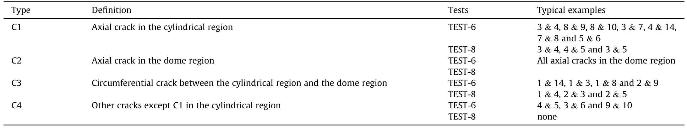
Table 4Classification of liner cracks.
Without other effective analytical methods, we assume that once the fibers break, the COPV wall will lose fiber-directional strength in the corresponding region, and the liner will also break.The assumption means that the CFRP cracks and the liner cracks have similar distribution locations and directions.The profiles of the CFRP layer and the liner layer of Fragment 4(Fig.17(b))in TEST-6 are approximately the same, roughly proving the above assumption.By analyzing the crack distribution, we preliminarily infer the process of the COPV rupture as follows: (1) The initial perforation was generated after the projectile impacted the front wall of the COPV.The crack C1 propagated from the perforation along the axial direction under the circumferential tensile stress,which is due to the small circumferential bearing capacity of the COPV.(2) The debris cloud formed by the impact of the projectile on the front wall and the gas shock wave in front of the debris cloud continued to propagate forward, and the regions with relatively small strength such as weld joints were also pulled apart due to the increase in the stress of the COPV wall caused by the gas shock wave, causing the crack C1 to propagate along the axial direction.(3) The debris cloud was decelerated and ablated in the highpressure gas, only the large central fragment(found by examining the inner side of the rear wall of the vessel)arrived at the rear wall of the vessel.The cracks C1 propagated axially from the perforation created by the large central fragment, and additional non-axial propagating cracks C4 were created at higher pressure levels(Fig.17(d), rear view).(4) With the propagation of the axial crack,when it reached the joint between the cylinder and the dome,part of it continued to propagate to the dome region and formed the crack C2,while the other part propagated along the circumferential direction and formed the crack C3 under the axial tension and shear force caused by gas expansion.The driving forces for crack propagation of the typical cracks C1, C2 and C3 are shown in Fig.17(e).
Although most of the major cracks can be explained using the above process,the detailed characteristics of some other cracks C4,such as location and direction, are still difficult to understand,which may be caused by the stress concentration due to the material defects and filament winding process.It should be noted that the above process does not follow a strict chronological order and may be affected by the initial pressure, impact velocity, COPV structure and other parameters, which need further research.
6.Conclusions
The damage to COPVs by HVIs with millimeter-sized projectiles was studied in experimental and numerical methods.The results of HVI tests show two typical damage modes: non-catastrophic damage and catastrophic damage.
For non-catastrophic damage, a valid numerical model was developed that can be used to study the perforation morphology,size, and stresses at the perforation edges of the front walls of the COPVs caused by HVI events.The results show that the tensile action of the rarefaction waves generated on the inner free surface of the COPV wall mainly causes the liner to bend inward.The COPV wall thickness, impact velocity and internal pressure will all have an effect on the perforation size.However,the effect of the internal pressure on them is very small compared to that of the impact velocity and COPV wall thickness.Numerical simulations of the stresses at the perforation edges show that the maximum tensile stress σepduring the impact is much greater than the average tensile stress σea’ in the final steady state, contributing to reasonably estimating whether the cracks spread unstably.
For catastrophic damage, the results of catastrophic damage tests indicate that the main crack initiation points are in the stress concentration regions,such as perforations and weld joints,and the cracks propagate along the directions of relatively small bearing capacities.With the increase in the initial internal pressure of the vessel, the number of fragments increases, and the crack distribution becomes more complex.In addition,the test data in this paper verified the effectiveness of the RLE recently developed by Schonberg.
Many points, such as quantitative limit conditions for crack instability propagation and the time sequence process of the pressure vessel rupture, remain open for further study.However,the tensile stress variation process at the perforation edges,experimentally collected fragment characteristics, and crack distribution of the COPVs in this paper can provide some references for further studies.
Declaration of competing interest
The authors declare that they have no known competing financial interests or personal relationships that could have appeared to influence the work reported in this paper.
Acknowledgments
This work was supported by the National Natural Science Foundation of China (Grant Nos.11672097,11772113).

- Defence Technology的其它文章
- The interaction between a shaped charge jet and a single moving plate
- Machine learning for predicting the outcome of terminal ballistics events
- Fabrication and characterization of multi-scale coated boron powders with improved combustion performance: A brief review
- Experimental research on the launching system of auxiliary charge with filter cartridge structure
- Dependence of impact regime boundaries on the initial temperatures of projectiles and targets
- On the effect of pitch and yaw angles in oblique impacts of smallcaliber projectiles