
Feasibility of Intermediate Fluid Vaporizer with Spiral Wound Tubes
2013-07-25 10:07LiuFengxiaDaiYuqiangWeiWeiZouJiupengZhuCheDongChaoHuDapeng
中国炼油与石油化工 2013年1期
Liu Fengxia; Dai Yuqiang; Wei Wei; Zou Jiupeng; Zhu Che; Dong Chao; Hu Dapeng
(School of Chemical Machinery Engineering, Dalian University of Technology, Dalian 116023)
Feasibility of Intermediate Fluid Vaporizer with Spiral Wound Tubes
Liu Fengxia; Dai Yuqiang; Wei Wei; Zou Jiupeng; Zhu Che; Dong Chao; Hu Dapeng
(School of Chemical Machinery Engineering, Dalian University of Technology, Dalian 116023)
A novel intermediate fluid vaporization (IFV) technology for LNG re-gasification process with spiral-wound heat exchanging tubes is proposed. The new IFV project combines the advantage of running the shell and tube heat exchangers at high pressure with the advantage of compact space of heat exchangers. Thermal analysis on the two processes of forced convection and vaporization type heat transfer in the spiral wound tubes and vapor condensation /re-boiling type of heat transfer via intermediate fluid in shell side shows the feasibility of this promising technology.
spiral-wound heat exchanger; intermediate fluid type vaporizer; LNG vaporizer
1 Introduction
Liquefied natural gas (LNG), with volume less than 1/600 compared to its gaseous state, is more practical and eff icient to store and transport. LNG must be re-vaporized to gaseous state prior to being used. The LNG re-gasification process is of great concern in terms of the operating cost and its possible impact on the environment.
As a typical base-load LNG vaporizer, the intermediate fluid vaporizers (IFV) are free from device switches and thus avoid the problem of freezing-induced blockage. Figure 1 shows a typical IFV structure[1-4], which includes three separated tube-and-shell heat exchangers. Typical intermediate fluids (IF) with low flash point, low viscosity and large latent heat, such as the propane, the refrigerant, or the water-glycol mixture, are used in the shell side of intermediate fluid vaporizer E1. Firstly the IF is vaporized by a heat medium, and then it is condensed by LNG on the surface of the tubes and finally descends to the bottom of the shell. Therefore, LNG inside the tubes is vaporized by the heat generated by the condensation of the intermediate fluid, and the resultant natural gas (NG) is heated by the heat exchanger E3 to a specified temperature before use. Improvements and advantages that make IFV an optimal choice for application of the base-load LNG vaporizer are as follows: the IFV is free from being frozen, hence there is no need for switch devices; IFV can use seawater even with large amount of sediments as the heat medium; it makes remarkable cost reduction because the titaniumtubes are suited to the seawater environment; and the environmental impact can be significantly reduced by using eco-friendly refrigerants with zero ozone depletion potential (ODP) and zero global warming potential (GWP).
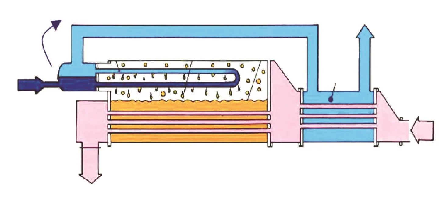
Figure 1 A typical intermediate fluid type vaporizer[5]
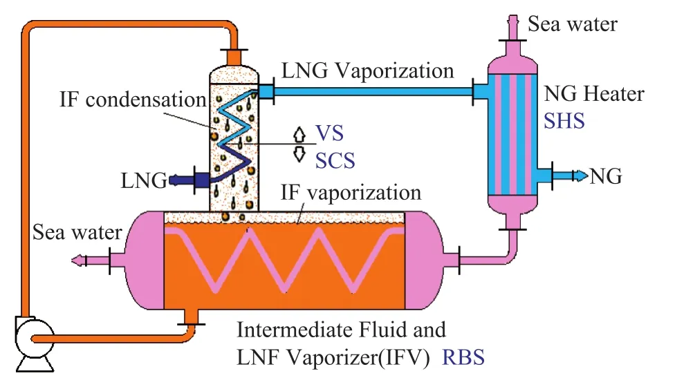
Figure 2 Schematic diagram of novel intermediate fluid vaporizer with Spiral Wound Tubes[6]
Despite all the advantages of conventional IFVs, there are still many problems that must be solved: Most of the tube sheets for heat medium fluids are very large, resulting in a dramatic increase of the investment; the self-circulation feature sometimes causes low startup speed of the device; the filling ratio of IF and the non-condensable gas have a great impact on the heat transfer efficiency; the interaction of evaporation section and superheat section adds to the difficulty related to the operation or equipment maintenance of IFV; and the usage at the floating storage and re-gasification units (FSRU) is limited due to its large size. This research work presents a novel IFV by using spiral wound tubes in the heat exchanging technology which originates from Linde AG[7].
2 Intermediate Fluid Vaporizer with Spiral Wound Tubes
For the application of IFV with spiral wound tubes to the LNG re-gasification units on marine terminals or platforms, some basic requirements should be satisfied, namely: compact structure with high thermal efficiency and small in size; no special requirements for the heat medium like seawater with huge amount of sediments; no potential of freezing and without device switches; and ease in operation with low maintenance cost.
All these features conform to today’s development of FSRU units. Accordingly, the following technical solutions are proposed:
(a) Using intermediate heat medium in the LNG vaporization process. Adoption of intermediate heat medium can ameliorate the freezing problem, which meets the needs of fast LNG vaporization and large heat flow (about 550 MMBTU/h).
(b) Utilizing compact spiral wound heat exchanger for the re-gasification process. The heat exchangers with spiral wound tubes operating under high pressure with multiple streams designed by DUT[8]have been widely used as the main cold box in the West-East NG Transport Project in recent years, which have replaced the costly imported high-pressure plate-fin heat exchangers. The spiral wound heat exchanger also exhibits technical advantages in LNG re-gasification process. Figure 2 shows the novel LNG re-gasification process with spiral wound heat exchanging tubes. The system is composed of a LNG super-cool section (SCS), a LNG vaporization section (VS), an IF re-boiling section (RBS) and a NG super-heat section (SHS). All these sections use the shell-and-tube type equipment to ensure the operation under high pressure. The sub-cooled LNG stream leaving the pre-pumps at about -161 ℃flows into the spiral wound tubes of vertical part of the IFV, and is gasified into NG with a temperature rise of 2 ℃—3 ℃. Both the sensible heat and latent heat of gasification are used to cool the IF gas into droplets in the shell side. Then the condensed IF droplets flow down to the bottom of shell side by forced circulation system to solve the problems of low start-up speed and adverse impact of non-condensable IF gases, when the IF operating condition is close to supercritical condition. The liquefied IF at the bottom of shell side is regasified by the heat medium such as seawater. Then the NG is heated by the heat medium in the heater E3 with a temperature rise equaling to 15 ℃, which meets the standard for the application or transportation needs.
3 Feasibility of the Novel IFV with Spiral Wound Tubes
3.1 Spiral wound tubes used in four sections
Being different from natural gas liquefaction processes, the re-gasification process of LNG takes place veryfast. And there is also a big difference in the heat transfer coefficients between condensation and vaporization processes[9-10]. The engineering practice shows that the heat transfer coefficient of the vaporization process is almost 100 times as large as that of liquefaction process. In other words, if 10 000 m2of heat exchanging area is needed for certain amount of NG to be liquefied into LNG, only 100 m2is required for its re-vaporization. Owing to the large specific surface area of heat exchanger with spiral wound tubes, which is close to a value of 200 m2/m3for spiral-plate heat exchanger, the employment of spiral wound heat exchanger can significantly reduce the equipment size. The heat transfer efficiency can be enhanced by reducing the temperature difference. High efficiencies can be ensured by small temperature difference in each stream of the heat exchanger employed in the re-vaporization process.
The spiral-wound heat exchanging technique is suited to both LNG liquefaction and LNG re-gasification processes perfectly owing to the unique features of high pressure-bearing capacity and high heat transfer efficiency at either a small or a large temperature difference. The employed equipment is more suitable for large-temperature-difference heat exchange during LNG re-vaporization. Besides the brittleness of materials under the low-temperature operating condition, large temperature stresses should also be avoided. The spiral wound heat exchanger has large flexibility because of its helical structure, which can attenuate the temperature stress.

Table 1 Typical operating regime of the new IFV unit
In view of the high pressure-bearing capacity characteristic of the tube-shell structure, and on the basis of all the above-mentioned comparison, conclusions can be drawn out that the spiral wound heat exchangers are the optimal choice for realizing the high-pressure, lowtemperature, and efficient heat exchanging.
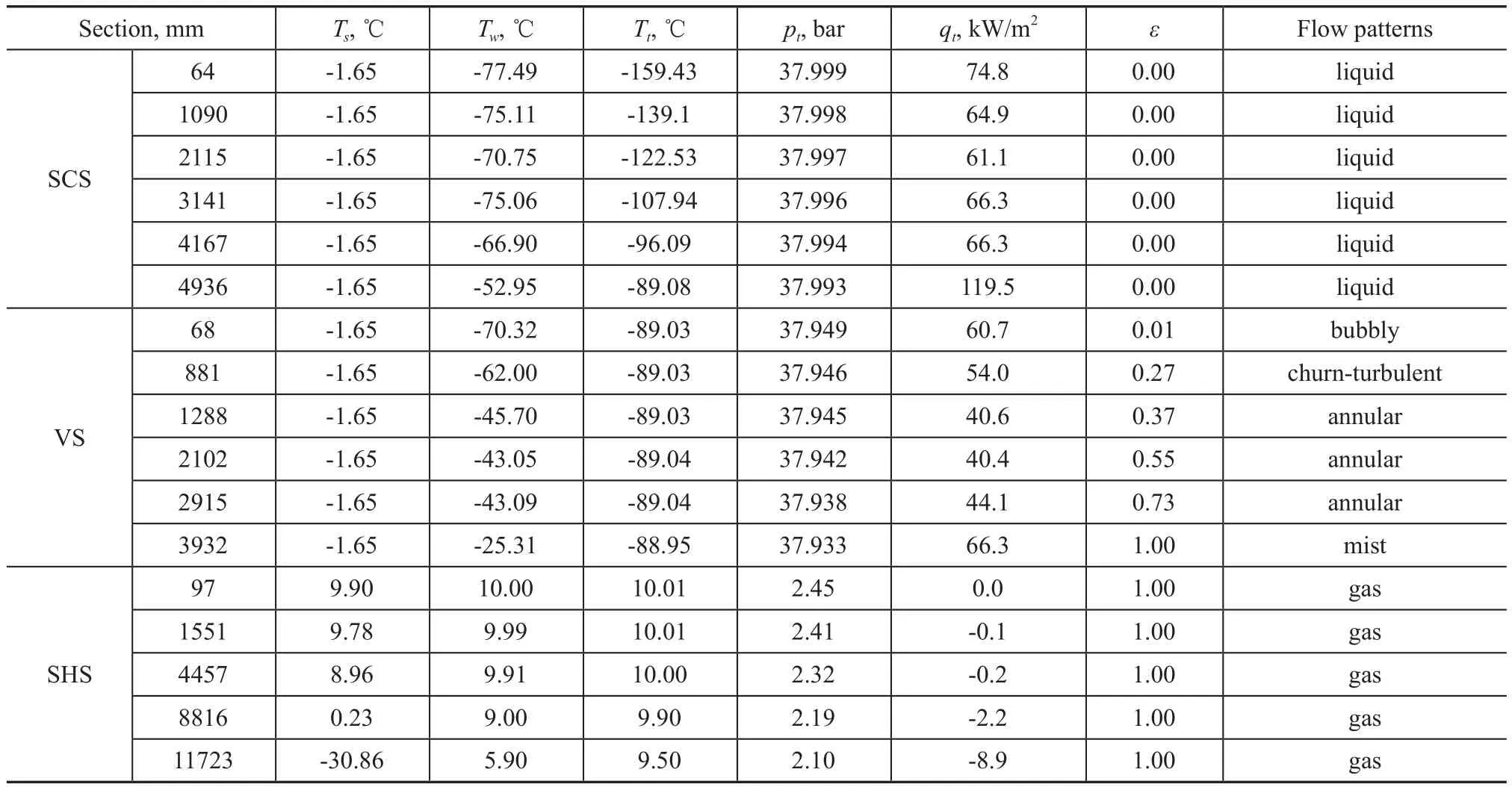
Table 2 Some segmented design data of three major sections
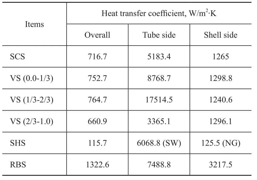
Table 3 Heat-transfer coefficient of each section
3.2 Temperature of tube wall in IFV
Sea water is often selected as the heat medium for its good availability. The seawater of East China Sea has a yearly mean temperature of 19 ℃ and contains suspended solids with a particle size of between 1 μm-20 μm. The temperature of seawater fluctuates between 4 ℃ to 6 ℃, which complies well with changes of normal marine environment. Table 1 shows the typical data of the new IFV unit rated at 500 kt/a operating at a vaporization pressure of 3.8 MPa. The operating pressure of IF is 0.45 MPa with a corresponding saturation temperature of -1.65 ℃. The optimum heat load of the superheat section is 5 370.7 kW, which is provided by a heating area of 1 492 m2which is about 110% of the required area. The tube bundle is composed of 1696 spiral wound tubes, measuring 14 000 mm in length, 20 mm in diameter and 1.5 mm in thickness. Some typical data of segmented design for the superheater section are shown in Table 2. The data of sub-cool section (SCS) with a heat load of 5 708.5 kW and those of vaporization section (VS) with a heat load of 3 269.7 kW are also shown in Table 2.
The study has disclosed that the LNG in SCS and VS must carry out heat exchange with the IF to avoid freezing induced blockage of heat medium. Table 3 shows the data on heat-transfer coefficients for each section. The heat transfer coefficient of LNG side far outweighs the condensing heat transfer coefficient of IF, so the heat transfer resistance mainly occurs on the shell side, then the tube wall temperature (-77.49 ℃ to -25.31 ℃) is close to that on the LNG side. At such a temperature, the seawater in the shell side would be frozen without using IFs.
However the IF like propane will not freeze until the temperature reaches -180 ℃ at 4.5 bar.
To enhance the computational accuracy of the gasification section, one needs re fining the segmentation sections. Table 3 shows the major difference in heat transfer coefficients at different gasi fication intervals. There is a great difference between the rates of gasi fication when nucleate boiling occurs at different operating pressure. The nucleate boiling appears at a gasi fication rateεof 0.3—0.7 at a pressure of 3.7 MPa, while at a pressure of 4.5 MPa it appears at a gasi fication rate. εof 0.2—0.6.
The superheat section can conduct heat exchange in a separated device. In the tube side of superheat section, the heat transfer is carried out in gaseous state with a small heat transfer coefficient. The tube wall temperature is close to that of heat medium without the occurrence of freezing. In general, the heat load of superheat section is greater than that of the gasi fication section. In fact, simple increase of the LNG operating pressure exerts no effect on diminishing equipment size due to increasing superheat load.
4 Conclusions
A novel intermediate fluid vaporization technology is proposed by using spiral wound tubes, which is particularly suitable for FSRU. The stream of LNG is routed through the sub-cool section in tube side to avoid temperature stress. In addition, the corrosive heat medium should flow through the spiral wound tubes of the heat exchanger. The size and thickness of the tube sheet for spiral wound tubes can be reduced signi ficantly, which is in favor of saving expensive titanium material. It realizes the separation between the superheat section and vaporization section thanks to the small heat transfer coefficient of gas phase. Thermal analysis of the new IFV on the two processes of forced convection vaporization heat transfer in the tubes and vapor condensation /re-boiling heat transfer in shell side shows the feasibility of this promising technology.
Acknowledgements:This work was supported by grants from the Fundamental Research Funds for the Central Universities (DUT12JN01) and the National Natural Science Foundation of China (51106017).
[1] Iwasaki M, Asada K. Intermediate Fluid Type Vaporizer: The United States, US6367429 [P], 2002-04-09
[2] Iwasaki M, Egashira S, Oda T, et al. Intermediate Terminate Fluid Type Vaporizer and Natural Gas Supply Method Using the Vaporizer: The United States, US6164247[P]. 2000-12-26
[3] Franklin D A. LNG Vaporizers. An Overview of LNG Vaporizer Technologies[R], Black & Veatch, Process Heat Transfer Society of Houston, 2006-03-22
[4] Ross F P, Walther S T, Cuellar K T. Advanced technologies provide improved economics for liquefied natural gas facilities[J]. Hydrocarbon Processing, 2008(1): 61-63
[5] Kobelco. Intermediate Fluid Vaporizer [R/OL]: http://www. kobelco.co.jp/english/machinery/products/ecmachinery/ lng/ifv.html
[6] Guo Yeyu, Li Minghui, Hu Dapeng, et al. LNG Regasification System and Method with Inter-medium Fluid: China, CN 201110333054.6[P], 2012-06-27
[7] Schneeberger, Martin, Wittmann. Heat Exchanger: The United States, US4084546[P]. 1978-04-18
[8] Spiral Wound Heat Exchanger, Applications News of Dalian University of Technology [EB/OL]: http://scidep.dlut.edu. cn/show.php?id=1142, 2011-06-27
[9] Finn A J, Johnson G L, Tomlinson T R. Developments in natural gas liquefaction [J]. Hydrocarbon Processing, 1999(4): 47-59
[10] Mehrpooya M, Vatani A, Mousavian S M A. Introducing a novel integrated NGL recovery process configuration (with a self-refrigeration system (open-closed cycle)) with minimum energy requirement[J]. Chemical Engineering and Processing, 2010, 49: 376-388
Recieved date: 2012-11-30; Accepted date: 2013-01-21.
Hu Dapeng, E-mail: hudp@dlut.edu.cn.

- 中国炼油与石油化工的其它文章
- Alumina Supported Vanadium Oxide Catalysts for Residue Hydrotreating
- Highlights on Planned Grassroots Styrene Units and Expansion of Existing Styrene Units in China
- Hydrocarbon Composition of Different VGO Feedstocks and Its Correlation with FCC Product Distribution
- Purification of Crude Glycerol from Waste Cooking Oil Based Biodiesel Production by Orthogonal Test Method
- Degradation of Nitrobenzene-Containing Wastewater with O3and H2O2by High Gravity Technology
- Et3NHCl-AlCl3Ionic Liquids as Catalyst for Alkylation of Toluene with 2-Chloro-2-methylpropane