
Optical flow based guidance system design for semi-strapdown image homing guided missiles
2016-11-24 02:25HungLnSongJinmeiZhngMinqingCiGohu
CHINESE JOURNAL OF AERONAUTICS 2016年5期
Hung Ln,Song Jinmei,*,Zhng Minqing,Ci Gohu
aKey Laboratory of Dynamics and Control of Flight Vehicle,Ministry of Education,School of Aerospace Engineering,Beijing Institute of Technology,Beijing 100081,China
bBeijing Aerospace Automatic Control Institute,Beijing 100854,China
Optical flow based guidance system design for semi-strapdown image homing guided missiles
Huang Lana,Song Jianmeia,*,Zhang Minqianga,Cai Gaohuab
aKey Laboratory of Dynamics and Control of Flight Vehicle,Ministry of Education,School of Aerospace Engineering,Beijing Institute of Technology,Beijing 100081,China
bBeijing Aerospace Automatic Control Institute,Beijing 100854,China
This paper focuses mainly on semi-strapdown image homing guided (SSIHG) system design based on optical flow for a six-degree-of-freedom (6-DOF) axial-symmetric skid-to-turn missile.Three optical flow algorithms suitable for large displacements are introduced and compared.The influence of different displacements on computational accuracy of the three algorithms is analyzed statistically.The total optical flow of the SSIHG missile is obtained using the Scale Invariant Feature Transform(SIFT)algorithm,which is the best among the three for large displacements.After removing the rotational optical flow caused by rotation of the gimbal and missile body from the total optical flow,the remaining translational optical flow is smoothed via Kalman filtering.The circular navigation guidance(CNG)law with impact angle constraint is the n obtained utilizing the smoothed translational optical flow and position of the target image.Simulations are carried out under both disturbed and undisturbed conditions,and results indicate the proposed guidance strategy for SSIHG missiles can result in a precise target hit with a desired impact angle without the need for the time-to-go parameter.
1.Introduction
Optical flow can be defined as the projection of relative 3D motion between an observer and a scene onto an image plane.1Optical flow is frequently used by insects and birds,and its employment is observable in honeybees through their grazing behavior and ability to achieve smooth landings.2In recent years,researchers have reported evidence that birds can also use optical flow for obstacle avoidance and landing maneuvering.3With its rich relative motion information,optical flow can be used with flight vehicles for such purposes as automatic takeoff/landing,4–7collision detection and avoidance,8,9guidance and control,10–12motion estimation and structure reconstruction,13and target tracking.14Optical flow will be utilized in the guidance design strategy for a semi-strapdown image homing guided (SSIHG) missile in this paper.The research in this area consists of two parts:analysis on the influence of large displacements on computational accuracy for three optical flow algorithms,and the guidance design strategy of the SSIHG missile based on optical flow with impact angle constraint.
A variety of algorithms have been used to calculate optical flow,the most popular of which are Lucas Kanade (LK),15Horn Schunck (HS),16Pyramid LK (PLK),17Scale Invariant Feature Transform(SIFT)18and Speed Up Robust Features(SURF).19Mammarella et al.20made a comparative study on the accuracy of nine different optical flow algorithms,including SIFT,LK and HS,using videos and showed that the SIFT algorithm provides the best performance.However,the computational accuracy of optical flow algorithms under different displacements was not analyzed.20Baker et al.21studied several well-known algorithms to obtain optical flow,including PLK and Black Anandan (BA),where the groundtruth flow was determined by tracking hidden fluorescent texture painted on the scene.However,the scene moved slowly,and no scene point moved by more than two pixels from one captured frame to the next.The accuracy of five optical flow algorithms was also compared by Bell et al.22Optical flow was used to provide an accurate estimate of the incremental position of an endoscope.However,the speed of the endoscope was also low,moving only in increments of about 2 mm each time.Most of the literature mentioned above discusses the computational accuracy of optical flow algorithms under small displacements.However,the optical flow of the SSIHG missile may sometimes be very large,so the first aim of this paper is to choose an optical flow algorithm that is suitable for large displacements.
Much research has been done on guidance laws with impact angle constraint.Lee et al.23designed an impact angle control guidance consisting of a proportional navigation guidance (PNG) command and continuous feedback on the difference between estimated intercept angle and the desired impact angle,which is added to the PNG command to provide a zero miss distance.A limitation is that this guidance law requires the estimation of time-to-go.A biased PNG with impact angle constraint was also proposed24that requires a tgo estimate.Beard et al.11demonstrated how PNG laws can be derived from optical flow information.However,such information is assumed to be known,and the paper does not show how to calculate it.A circular navigation guidance (CNG) based on optical flow was presented by Manchester et al.12It indicated that guidance law can result in zero miss distance,and impact angle error tends to zero when the target moves slowly.However,the missile was regarded as a mass point,so the effect of the rotation of the missile body was not considered in the processing of optical flow information.This paper will make further research based on the work of Manchester while fully accounting for missile body and gimbal rotation.
The main contributions of this research are as follows:First,the influence of different displacements,especially large displacements,on three optical flow algorithms is given through statistical simulations,and their application scopes are presented.Second,the total optical flow of the SSIHG missile is obtained by using the SIFT algorithm,and the n the optical flow information is decomposed and filtered,fully taking into account the rotational movement of the missile body and gimbals.Finally,closed-loop simulation of the entire SSIHG system is accomplished using a six-degree-of-freedom (6-DOF) dynamics model of the missile where the target image is constructed by mathematical computer simulation based on the pinhole model for the image detector.
The structure of the paper is organized as follows:Section 2 defines relevant coordinates in the SSIHG missile,and establishes the kinematics and dynamics model of the missile with 6-DOF;the dynamics model of the gimbal control system is built,and the pinhole model for the image detector is introduced.Section 3 analyzes the influence of different displacements on the computational accuracy of the optical flow algorithms.In Section 4,the CNG law with impact angle constraint based on translational optical flow is obtained.The decomposition and the filtering of optical flow information are given in Section 5.Section 6 demonstrates the closedloop simulation of the entire SSIHG system,and conclusions are in Section 7.
2.Mathe matical models of SSIHG system
2.1.Definitions and transformations of coordinate frames
The image detector of the SSIHS is mounted on the missile body using two gimbals.An outer gimbal is for yaw,and an inner gimbal corresponds to pitch.The image detector,which can rotate around both the yaw and pitch axes,is installed in the inner gimbal.The definitions and transformations of the coordinate frames used herein are explained below,and the three axes in all following coordinate frames are righthanded orthogonal.
(1)Axiyiziis the inertial coordinate frame.The origin A is the projection of the missile launch point along the vertical plane on the ground.Axiaxis is located in the horizontal plane with its positive direction pointing to the target.Ayiaxis is located in the vertical plane containing Axiaxis,and its positive direction points upwards.
(2)Oxbybzbis the missile body coordinate frame.The origin O is located at the centroid of the missile.Oxbcoincides with the longitudinal axis of the missile body,and its positive direction points to the head of the missile.Oybis located in the longitudinal symmetric plane of the missile body with its positive direction pointing upwards.
(3)Oxsyszsis the line-of-sight(LOS)coordinate frame.Oxsaxis coincides with the LOS,and its positive direction points to the target.Ozsaxis is located in the Axiziplane and is perpendicular to Oxsaxis.
(4)Oxoyozois the outer(yaw)gimbal coordinate frame.Oxois perpendicular to the outer gimbal plane with its positive direction pointing to the target.Oyocoincides with Oybaxis.Ozolocates in the Oxbybplane.
(5)Oxinyinzinis the inner(pitch)gimbal coordinate frame.Oxinaxis coincides with the optical axis of the image detector.Ozinaxis coincides with Ozoaxis.Oyinaxis is located in the Oxoyoplane.
(6)Oxcyczcis the detector coordinate frame.Ozcand Oycaxes coincide with the Oxinand Oyinaxes,respectively.Oxcaxis is located in the Oxbzbplane.
(7)Opxpypzpis the image plane coordinate frame.The origin Opis the center of the image plane.Opxpaxis in the image plane is parallel to the Oxcaxis,and its positive direction is consistent with Oxcaxis.Opypaxis is parallel to the Oycaxis.
The coordinate frames of the SSIHG system are depicted in Fig.1.The angle λzbetween Oxinand Oxois the rotational angle of the inner gimbal.The angle λybetween Oxoand Oxbis the rotational angle of the outer gimbal.
The transformation matrix from Oxbybzbto Oxinyinzinis

The transformation matrix from Axiyizito Oxbybzbis


where ϑ,ψ and γ are the attitude angles of the missile body.25The transformation from Oxinyinzinto Oxcyczcis

So the transformation from Oxcyczcto Axiyiziis

2.2.Dynamics model of missile with 6-DOF
The dynamics model of the skid-to-turn missile with 6-DOF is established in this paper according to Newton's second law and Momentum Moment Theorem.25The equations can be written as follows:

Fig.1 Coordinate frames of SSIHG system.
where m represents the mass of the missile;θ represents the flight path angle;ψvrepresents the heading angle;α,β and γvare the angle of attack,angle of sideslip and bank angle,respectively;x,y and z represent the position of the missile in the inertial coordinate frame;P is the engine thrust;X,Y and Z are the drag,lift and side force,respectively;Jx,Jyand Jzare the missile body's moments of inertia;Mx,Myand Mzare the aerodynamic moments of the missile body;ωx,ωyand ωzare the rotational angular rates of the missile body relative to the inertial coordinate frame;VMis the speed of the missile;mcis the fuel weight flow rate.The flying direction of the missile is actuated by the air rudder.A traditional acceleration autopilot is designed using the PID control theory,which improves the damping characteristic of the missile and the missile's response to the guidance command.For the sake of brevity,the design process of the autopilot is omitted here.
2.3.Pinhole model for image detector and dynamic model of gimbal control system
The image detector is mounted on the gimbals.The optical axis of the image detector can track the LOS quickly,which maintains the target image around the center of the image field.The pinhole model of the detector is shown in Fig.2,where Ozcis the optical axis of the detector,and fis the focal length of the detector.is the location of target in the detector coordinate frame,denoted as T;T′is the corresponding projection point of T on the image plane,and its coordinate is.Therefore,the vector OT′can be expressed asand scz=f.

Fig.2 Pinhole model of detector.
According to the projection principle,the relationship between the coordinates T and T′can be obtained as

siis the corresponding vector of scin the inertial coordinate frame.It is calculated as

The elevation and azimuth LOS angles are named as qzand qy,respectively.qzis the angle between siand the Axiziplane.qyis the angle between Axiaxis and the projection of siin the Axiziplane.The expressions of qzand qyare given by

The gimbals are controlled so that the target image remains around the center of the image field.In other words,the gimbal servo system is designed to ensure that the optical axis of the detector tracks the LOS as quickly as possible.For convenience,the dynamics of the gimbal control system can be simplified as a first-order system,and the transfer functions of the gimbal control system are given by

where k1and k2are positive constants;azand ayare the control commands of inner gimbal and outer gimbal,respectively.The expressions of azand ayare shown as

where

3.Influence of displacement on computational accuracy for three optical flow algorithms
3.1.Brief introduction of optical flow algorithms
This paper mainly researches the influence of different displacements on the computational accuracy of optical flow algorithms in order to find the best one for the SSIHG missile.Some algorithms are used commonly to compute optical flow,including LK,HS,PLK,SIFT and SURF.The main disadvantage of LK and HS algorithms is that the calculation of spatial and temporal derivatives is usually very prone to errors,especially in situations with relatively fast motion.20So,this paper analyzes the accuracy and application scopes of PLK,SIFT and SURF algorithms.The basic principles of these three optical flow algorithms are introduced first,and the n simulation experiments are carried out for statistical analysis.
The PLK17is an improved version of the LK algorithm.In implementation,Gaussian pyramids are constructed by downsampling the original image pair by a factor of 2.The overall PLK algorithm proceeds as follows:first,the initial estimation of optical flow at the coarsest pyramid level l is initialized as zero.The residual optical flow at level l is obtained by using the standard LK algorithm,and the n added to the initial value to shape the optical flow of level l.After the optical flow of level l is affine transformed,it is propagated to level l-1,and regarded as the initial value of the optical flow of level l-1.The same procedure goes on until the optical flow of level l=0 is calculated,which is the optical flow between the two original image pairs.
The SIFT algorithm18can provide robust matching across a substantial range of geometric distortions,changes in 3D viewpoint and illumination.The principles of the SIFT algorithm can be divided into five major stages.First,the locations of potential interest points are obtained by using a differenceof-Gaussian function.Second,at each candidate location,a detailed model is fit to determine the localization and scale of keypoints.Third,an orientation histogram is formed from the gradient orientations of sample points around the keypoint,and the peaks in the orientation histogram correspond to the dominant directions of local gradients.Fourth,the local image gradients are measured at the selected scale around each keypoint and the n form the keypoint descriptors with n dimensions.Finally,the best candidate match for each keypoint is found by identifying its nearest neighbor in a database of keypoints from training images.The displacement of corresponding keypoints can be obtained after feature matching,and the displacement is the optical flow.In order to testify to the performance of the SIFT algorithm,two pictures of a toy car are taken from different angles.The matching result using the SIFT algorithm is very good and shown in Fig.3.
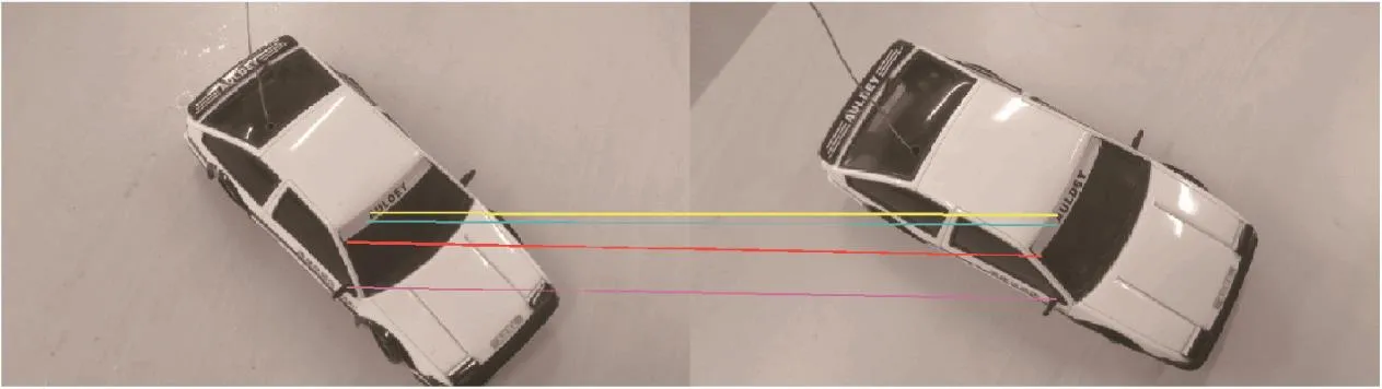
Fig.3 Matching result of a toy car using SIFT.

Fig.4 Matching result of a toy car using SURF.
The SURF19algorithm obtains optical flow also by measuring the displacements of certain image features.However,its computational principles are slightly different from SIFT.SURF builds its scale space by keeping the image size the same and only varying the size of the box filter.The extrema of the determinants of the Hessian matrix are the n used to detect the keypoints.Each detected keypoint is first assigned a reproducible orientation.For orientation,Haar wavelet responses are calculated for a set of pixels.Using the same original pictures as in SIFT,the matching result by utilizing the SURF algorithm is shown in Fig.4.It can be seen that the SURF algorithm can also provide good matching.
3.2.Simulation analysis of different displacements on the accuracy of three optical flow algorithms
This section demonstrates the influence of different displacements on the computational accuracy of PLK,SIFT and SURF algorithms via simulations.The target is assumed to be stationary with a size of 5 mX5 m,and its coordinates are(108,0,0)m in the inertial coordinate frame.For research convenience,the image detector is assumed to move at different speeds straightly along the Axiaxis at the altitude of 600 m,and its initial position is(0,600,0)m.The image detector uses an 800X800 pixel square array.The speeds of the image detector in the inertial coordinate and image plane coordinate are listed in Table 1.A series of target images are obtained when the image detector moves.The mean μ and standard deviation δ of the optical flow based on the three algorithms under different image detector speeds can be seen in Table 1(subscripts indicate algorithm).
It can be seen from Table 1 that accuracy of the PLK algorithm is lower than that of the SIFT algorithm;When the displacement becomes larger,the accuracy of PLK decreases.The SIFT algorithm was developed to detect and associate the same features between different images,and it has no restrictions for dealing with optical flow computation in fast motion situations.So the accuracy of the SIFT algorithm is maintained even when the displacement is large.As Table 1 shows,the differences between μSIFTand μSURFare not very significant.However,δSURFis larger than δSIFTin general,indicating that the computational accuracy of the SURF algorithm is lower than that of the SIFT algorithm.Therefore,for the remainder of this paper,total optical flow of the SSIHG system is calculated using SIFT.
4.CNG law with impact angle constraint
4.1.Basic principle of CNG
A schematic diagram of CNG12in a two-dimensional plane is visualized in Fig.5,where the point M is the missile's initial position,T is the target position,is the LOS,VFis the desired final velocity vector of the missile,λ is defined as the angle between the missile's current velocity vector VMand the LOS,ε is defined as the angle between LOS and VF,and VDis defined as the desired missile velocity and is the reflection of VFwith respect to LOS.During the flight,if the missile maintains the desired velocity VD,the angles λ and ε will be strictly equal.This results in the missile taking a circular path to hit the target with the desired impact angle.
The 2D geometric principles mentioned above can be applied to the three-dimensional guidance problem.The control command of CNG is composed of two parts:
(1)Impact angle control command a1,whose function is to rotate VMtoward VD.
(2)Proportional guidance command a2,whose function is to force the angular rate of VMto be the same as that of VD.
The specific expressions of the two control commands are derived as follows.
4.2.Impact angle control command
According to the principles of the CNG,VDand VFare symmetrical with respect to the LOS.So the expression of VDis given by


where eλis the error angle between the current velocity VMand the desired velocity VD;k is a positive constant;the direction of the impact angle control command UD1is given by

Table 1 Computational results of three optical flow algorithms.

Fig.5 Schematic diagram of CNG.

4.3.Proportional guidance command
The proportional guidance command is obtained based on optical flow information.The LOS angular rate Ωcin the detector coordinate frame is11

where the notationXis the cross product of the vectors;η is the translational optical flow,which will be obtained in the next section.The LOS angular rate Ωsin the LOS coordinate frame can be computed from Ωcas

where

Then the proportional guidance command a2can be calculated as

where the notation UD2is the direction of the proportional guidance command and it is given by

It can be seen that the CNG law does not need tgo information.
5.Computation and filtering of translational optical flow
Total optical flow d=[u,v]Tis obtained by using the SIFT algorithm,where u and v are the optical flow along the Opxpaxis and Opypaxis,respectively.The total optical flow of the target on the image plane can be decomposed into three components:

where d1is the translational component due to the relative movement of the missile and the target,and d1is the signal required by the CNG law;d2and d3are the rotational optical flow due to the rotation of the missile body and the gimbals,respectively.

Then d2is26

Suppose that the rotational angular rates of the outer and inner gimbal are˙λyand˙λz,respectively,the n the rotational angular rate of the inner gimbal relative to the missile body coordinate frame in the detector coordinate frame can be expressed as

Then d3can be calculated as
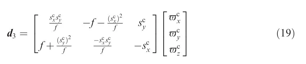
From Eq.(15)to Eq.(19),we can get d1.
The performance of the guidance system will be affected directly by the signal quality of d1.Due to the basic calculation principles of optical flow algorithms and the pixel size of the image plane,d1will not be smooth.To address this issue,Kalman filtering is used for smoothing the translational optical flow d1.The state and measurement equations of the Kalman filter are designed as follows.

where the state vector of the Kalman filter is denoted aswith ukfand vkfthe translational optical flows filtered by the Kalman filter;A and C are identity matrices;wkis the noise vector of the state;Ykis the measurement vector;and vkis the measurement noise vector.The recursive process of the Kalman filter is omitted here for brevity.Xkis actually the translational displacement between the missile and target in the image plane,so η=[ukf,vkf,0]T.

Fig.6 Schematic diagram for the closed-loop simulation of SSIHG system.

Fig.7 Simulation results of SSIHG system without disturbances.

Fig.8 Simulation results of SSIHG system under disturbances.
6.Closed-loop simulation of SSIHG system based on optical flow
6.1.Parameter settings and schematic diagram of simulations
To verify the correctness and the effectiveness of the designed SSIHG system,the closed-loop simulation of an SSIHG system based on optical flow is carried out.The initial positions of the missile and target in the inertial coordinate frame are set as(600,0,200)m and(0,200,0)m,respectively.The target is assumed to be stationary with the size of 4 mX4 m.The velocity of the missile is set as 200 m/s.Both the flight path and the heading angles are initially set as 0°.The three initial attitude angles of the missile body are all set as 0°.The pixel number of the image plane of the detector is 820X820.During the simulations,the roll angle of the missile body is assumed to oscillate in the manner of a sinusoidal function,i.e.,γ=5sin(5t).A schematic diagram for the closed-loop simulation of the SSIHG system are shown in Fig.6.
The desired impact angles in the pitch and yaw planes are all set as-30°.The parameters of the CNG law are designed as k=0.5,k1=k2=20.
6.2.Experiment 1:Simulation without disturbances
Firstly,it is assumed that there are no disturbances in the SSIHG system.The aim of the simulation is to verify the correctness of the proposed guidance strategy for the SSIHG missile based on optical flow.The simulation results are depicted in Fig.7.The final miss distance of the system is 0.42 m,and the error of the impact angles is 0.64°and 0.46°in pitch plane and yaw plane,respectively.
Fig.7(a)and(b)is the flight trajectories of the missile in pitch and yaw planes,respectively.Fig.7(c)and(d)is the flight path angle and heading angle,respectively.Fig.7(e)and(f)is the curves of the gimbal angle λyand λz,respectively.It can be seen that the optical axis can track the LOS quickly through the fast rotational movement of the gimbals,thus the SSIHG system does not need a detector with large field of vision(FOV).Fig.7(g)and(h)is the total optical flows of the SSIHG system,where the thick solid lines represent theoretical values and the thin dashed lines represent the realistic values that are calculated out by the SIFT algorithm.It can be seen that the initial displacement is very large,however the computational accuracy of the SIFT algorithm is very high and the computation error is less than one pixel.Fig.7(i)and(j)is the curves of the elevation and azimuth angular rates of LOS,respectively,where the thick solid lines represent theoretical values,and the thin dashed lines represent those deduced from optical flows.All indications are that the Kalman filter can smooth the optical flow very well,and the information for the LOS angular rates can be derived from the translational optical flow and used for the SSIHG missile effectively.
Simulation results show that the guidance strategy chosen for the SSIHG missile based on optical flow is reasonable and correct.
6.3.Experiment 2:Simulation under disturbances
The objective of the following simulation is to verify the effectiveness and robustness of the proposed guidance strategy for the SSIHG missile under disturbances.Since optical flow uncertainties are difficult to model,we simply assume that the total optical flow d computed by the SIFT algorithm and IMU measurements are corrupted by noise.The measured value of the total optical flow is assumed as27ds=d(I+ws),where wsis a random vector with Gaussian distribution N(0,0.22).The measured value of IMU is assumed aswhereis the realistic angular rate of the missile,and wtis a three-dimensional random vector with Gaussian distribution N(0,0.152).The simulation results with the disturbances are shown in Fig.8.The final miss distance is 0.48 m,and the error of the impact angles is 0.56°and 0.54°in the pitch and yaw planes,respectively.
Fig.8(a)and(b)is the total optical flows of the SSIHG system,where the thin solid lines represent realistic optical flow with noise.Fig.8(c)–(e)is the IMU measurements of the rotational angular rate of the missile body,shown as the thin dashed lines.Fig.8(f)and(g)is the curves of the elevation and azimuth angular rate of LOS,respectively.It can be seen that even with disturbance noise in total optical flow and angular rate,the LOS angular rate can be deduced correctly.
All the above simulation results indicate that the proposed guidance strategy for the SSIHG missile,including the optical flow algorithm based on SIFT,the decomposition and filtering of the optical flow,and the CNG law,are reasonable and effective.The proposed guidance strategy allows for the SSIHG missile to hit a target with a desired impact angle and small miss distance.
7.Conclusions
The guidance system design of the SSIHG system based on the optical flow for the 6-DOF axial-symmetry skid-to-turn missile is presented in this paper.The information of time-to-go is not required in the SSHIG system,which is important for the guidance strategy to be applied in the practical engineering.
(1)Three optical flow algorithms,including PLK,SIFT and SURF are introduced and compared by statistical simulations in order to choose the best one for the SSIHG missile.Simulation results indicate that the SIFT can provide the best performance even under large displacement.
(2)The proposed guidance strategy for SSIHG missile,including SIFT optical flow algorithm,the decomposition and filtering of optical flow information and CNG law,can make the missile hit target precisely with a desired impact angle.
Acknowledgement
This work was supported by the Armament Research Fund of China(No.9020A02010313BQ01).
1.Chao H,Gu Y,Napolitano M.A survey of optical flow techniques for robotics navigation applications.J Intell Robot Syst 2014;73(1–4):361–72.
2.Chahl JS,Srinivasan MV,Zhang SW.Landing strategies in honeybees and applications to uninhabited airborne vehicles.Int J Robot Res 2004;23(2):101–10.
3.Bhagavatula PS,Claudianos C,Ibbotson MR,Srinivasan MV.Optic flow cues guide flight in birds.Curr Biol 2011;21(21):1794–9.
4.He´risse´B,Hamel T,Mahony R,Russotto FX.Landing a VTOL unmanned aerial vehicle on a moving platform using optical flow.IEEE Trans Robot 2012;28(1):77–89.
5.Izzo D,Croon GD.Landing with time-to-contact and ventral optic flow estimates.J Guid Control Dynam 2012;35(4):1362–7.
6.Valette F,Ruffier F,Viollet S.Biomimetic optic flow sensing applied to a lunar landing scenario.In:IEEE international conference on robotics and automation;2010 May 3–8;Anchorage,Alaska.Piscataway(NJ):IEEE Press;2010.p.2253–60.
7.Termtanasombat N.Development of hardware-in-the -loop facility for optical navigation with the study of insect inspired algorithm for spacecraft landing[dissertation].Lulea:Lulea University;2010.
8.Dur E.Optical flow-based obstacle detection and avoidance behaviors for mobile robots used in unmanned planetary exploration.In:2009 4th international conference on recent advances in space technologies;2009 Jun 11–13;Istanbul,Turkey.Piscataway(NJ):IEEE Press;2009.p.638–47.
9.Eresen A,˙Imamog˘lu N,Efe MO¨.Autonomous quadrotor flight with vision-based obstacle avoidance in virtual environment.Expert Syst Appl 2012;39(1):894–905.
10.Holt RS,Beard RW.Vision-based road-following using proportional navigation.J Intell Robot Syst 2010;57(1–4):193–216.
11.Beard RW,Curtis JW,Eilders M,Cloutier JR.Vision aided proportional navigation for micro air vehicles.In:Proceedings of the AIAA guidance,navigation and control conference and exhibit;2007 Aug 20–23;Hilton Head,South Carolina.Reston:AIAA;2007.p.20–3.
12.Manchester IR,Savkin AV,Faruqi FA.Method for optical-flowbased precision missile guidance.IEEE Trans Aero Electron Syst 2008;44(3):835–51.
13.Zhang CX,Chen Z,Li M,Sun KQ.Direct method for motion estimation and structure reconstruction based on optical flow.Opt Eng 2012;51(51):2512–6.
14.Watanabe Y,Fabiani P,Besnerais GL.Air-to-Ground target tracking in a GPS-denied environment using optical flow estimation.In:Proceedings of the AIAA guidance,navigation,and control conference;2009 Aug 19–22;Boston,Massachusetts.Reston:AIAA;2009.
15.Lucas BD,Kanade T.An iterative image registration technique with an application to stereo vision.In:1981 7th international joint on artificial intelligence conference;1981 Aug 24–28;Vancouver.San Francisco:Morgan Kaufmann;1981.p.674–9.
16.Horn BK,Schunck BG.Determining optical flow.Artif Intell 1981;17(1–3):185–203.
17.Bouguet JY.Pyramidal implementation of the affine Lucas Kanade feature tracker description of the algorithm.Intel Corp Microprocessor Res Labs Tech Rep 2000;22(2):363–81.
18.Lowe DG.Distinctive image features from scale-invariant keypoints.Int J Comput Vision 2004;60(2):91–110.
19.Bay H,Tuytelaars T,Gool VL.Surf:speeded up robust features.Comput Vis Image Underst 2006;110(3):404–17.
20.Mammarella M,Campa G,Fravolini ML,Fravolini ML,Napolitano MR.Comparing optical flow algorithms using 6-dof motion of real-world rigid objects.IEEE Trans Syst Man Cybernet C 2012;42(6):1752–62.
21.Baker S,Scharstein D,Lewis JP,Roth S,Black MJ,Szeliski R.A database and evaluation methodology for optical flow.Int J Comput Vision 2011;92(1):1–31.
22.Bell CS,Puerto GA,Mariottini GL,Valdastri P.Six dof motion estimation for teleoperated flexible endoscopes using optical flow:a comparative study.In:IEEE international conference on roboticsamp;automation;2014 May 31–Jun 7;Hong Kong.Piscataway(NJ):IEEE Press;2014.
23.Lee CH,Kim TH,Tahk MJ.Interception angle control guidance using proportional navigation with error feedback.J Guid Control Dynam 2013;36(5):1556–61.
24.Gao F,Tang SJ,Shi J,Guo J.A bias proportional navigation guidance law based on terminal impact angle constraint.Trans Beijing Inst Technol 2014;34(3):277–82[Chinese].
25.Qian XF,Lin RX,Zhao YN.Missile flight dynamics.Beijing:Beijing Institute of Technology Press;2012.p.28–48[Chinese].
26.Markel MD,Lopez J,Gebert G,Evers J.Vision-augmented GNC:passive ranging from image flow.In:Proceedings of the AIAA guidance,navigation and control conference and exhibit;2002 Aug 5–8;Monterey,California.Reston:AIAA;2002.
27.Rhudy MB,Gu Y,Chao HY,Gross JN.Unmanned aerial vehicle navigation using wide-field optical flow and inertial sensors.J Robot 2015;6:1–12.
Huang Lanis currently working toward a Ph.D.at the School of Aerospace Engineering,Beijing Institute of Technology.Her research interests include cooperative control and vision-based navigation and guidance for flight vehicles.
Song Jianmeiis a supervisor of Ph.D.students and an associate professor at the Beijing Institute of Technology.Her main research interests include cooperative control for flight vehicles,aircraft dynamics modelling and control system design,strapdown homing guidance,filter design,and system optimization.
Zhang Minqiangreceived his M.S.from the School of Aerospace Engineering,Beijing Institute of Technology in 2016.His research interests include cooperative search and control for flight vehicles.
Cai Gaohuareceived his Ph.D.from the School of Aerospace Engineering,Beijing Institute of Technology.He is now working at the Beijing Aerospace Automatic Control Institute.His research interests include semi-strapdown homing guidance and autopilot design for flight vehicles.
1 September 2015;revised 12 May 2016;accepted 26 July 2016
Available online 27 August 2016
Guidance strategy;
Impact angle;
Optical flow;
Scale Invariant Feature
Transform(SIFT);
Semi-strapdown image homing guided (SSIHG) missile
©2016 Production and hosting by Elsevier Ltd.on behalf of Chinese Society of Aeronautics and Astronautics.This is an open access article under the CC BY-NC-ND license(http://creativecommons.org/licenses/by-nc-nd/4.0/).
*Corresponding author.Tel.:+86 10 68911929.
E-mail addresses:3120120008@bit.edu.cn(L.Huang),sjm318@bit.edu.cn(J.Song).
Peer review under responsibility of Editorial Committee of CJA.
 CHINESE JOURNAL OF AERONAUTICS2016年5期
- CHINESE JOURNAL OF AERONAUTICS的其它文章
- Flapping wing micro-aerial-vehicle:Kinematics,membranes,and flapping mechanisms of ornithopter and insect flight
- A new non-linear vortex lattice method:Applications to wing aerodynamic optimizations
- Experimental study of flow field distribution over a generic cranked double delta wing
- Streamwise-body-force-model for rapid simulation combining internal and external flow fields
- An artificial neural network approach for aerodynamic performance retention in airframe noise reduction design of a 3D swept wing model
- effects of wing locations on wing rock induced by forebody vortices