
Study on Performance of Laminated Porous Metal Fiber Sintered Felt as Catalyst Support for Methanol Steam Reforming Microreactor
2017-05-09 15:37KeYuzhiZhouWeiTangXiaojinZhangJinleiYuWeiZhangJunpeng
中国炼油与石油化工 2017年1期
Ke Yuzhi; Zhou Wei; Tang Xiaojin; Zhang Jinlei; Yu Wei; Zhang Junpeng
(1. Department of Mechanical & Electrical Engineering, Xiamen University, Xiamen 361005; 2. SINOPEC Research Institute of Petroleum Processing, Beijing 100083)
Study on Performance of Laminated Porous Metal Fiber Sintered Felt as Catalyst Support for Methanol Steam Reforming Microreactor
Ke Yuzhi1; Zhou Wei1; Tang Xiaojin2; Zhang Jinlei1; Yu Wei1; Zhang Junpeng1
(1. Department of Mechanical & Electrical Engineering, Xiamen University, Xiamen 361005; 2. SINOPEC Research Institute of Petroleum Processing, Beijing 100083)
In this study, the laminated porous metal fber sintered felt (PМFSF) functioning as catalyst support was used in a cylindrical methanol steam reforming (МSR) microreactor for hydrogen production. The PМFSF was fabricated by the low temperature solid-phase sintering method using metal fibers such as copper fibers and aluminum fibers which are obtained by the multi-tooth cutting method. The two-layer impregnation method was employed to coat Cu/Zn/Al/Zr catalyst on the PМFSF. The effect of fber material, uniform porosity and gradient porosity on the performance of methanol steam reforming microreactor was studied by varying the gas hourly space velocity (GHSV) and reaction temperature. Our results showed that the loading strength of porous copper fber sintered felt (PCFSF) was better than porous aluminum fber sintered felt (PAFSF). Under the same reaction conditions, the PCFSF showed higher methanol conversion and more H2output than PAFSF. Мoreover, the gradient porosity (Type 5: 90%×80%×70%) of PМFSF used as the catalyst support in microreactor demonstrated a best reaction performance for hydrogen production.
microreactor; methanol steam reforming; catalyst support; metal fber; hydrogen production
1 Introduction
Microreactor has been widely applied in various chemical reactions thanks to its small size, high specific surface area and excellent heat and mass transfer characteristics. Nowadays, the liquid hydrocarbon as fuel can be instantaneously converted into hydrogen-rich gas under appropriate catalytic reaction conditions[1-2]. This approach provides a new feasible idea to solve the hydrogen source problem for fuel cell. Thus, the research work about the microreactor for hydrogen production is attracting more attention of researchers[3]. The microreactor with porous materials used as catalyst support is characterized by a short reaction flow path and low pressure drop. Also, the catalyst supports usually have three-dimensional porous structure and large specific surface area, so the catalyst can be easily coated on the porous materials to form a stable catalyst structure[4-5]. The porous materials become a promising catalyst support for the microreactor designated for hydrogen production. Up to now, various materials such as the metal foam[6-8], the porous metal fiber materials[9-11]and the porous ceramics[12]have been developed and used in various catalytic reaction processes.
Metal foams are usually fabricated by means of direct forming of metals, which have three dimensional pore structure, high specific surface area and low density. However, the fabrication of metal foam needs the specialized equipment with high production cost. These disadvantages would prevent the widespread application of metal foams[13]. To date, the copper foams, nickel foams, FeCrAl foams, etc., have been widely used in various types of catalytic reaction processes. For example, Pestryakov[14]studied the performance of catalyst loaded on copper foam and silver foam by the partial oxidation reaction of ethanol in order to compare with the performance of traditional metal pumice catalyst. The metal foams not only have a non-uniform pore structurewith high porosity to produce a large contact area between the reactants and catalyst support, but also have the bend flow channels to greatly increase the heat transfer performance. Thus, the catalytic reaction performance of metal foam coated with catalyst can be significantly improved[15].
Porous metal fiber material as a new type of porous metal materials can be fabricated using the metal fiber, which has three-dimensional reticulated structure, interconnected pores, high porosity, and large specific surface area[11]. Hence so far, the design, manufacturing, and performance optimization of porous metal fiber material have been extensively studied. Wang[16-17]employed the micro-CT technique to produce the X-ray tomography images of porous metal fiber sintered sheet with an 80% porosity. The fracture behavior of a novel porous metal fiber sintered sheet was predicted using a semi-empirical method combining the knowledge of its morphological characteristics and micro-mechanical responses. Jin, et al.[18-19]proposed a micromechanics random beam model to investigate the elasto-plastic behavior of porous metal fber sintered sheets. The effects of three types of defects on the mechanical properties of porous metal fiber sintered sheets were investigated by means of a combination of numerical simulation, analytical modeling, and experimental test.
In recent year, different types of porous fiber materials have been developed for various catalytic chemical reactions. Ling, et al.[20]fabricated a tailorable sinterlocked microfibrous carrier consisting of 3.5 vol% of Ni-fibers with a diameter of 8 mm to entrap 35 vol% of catalyst particulates with a grain size of 150—250 mm for both methanol steam reforming (MSR) and CO preferential oxidation. The high efficiency hydrogen production by the MSR reaction was observed using the microfbrous entrapped Pd-ZnO/Al2O3catalyst packing. In the present study, the PМFSF with different porosity was manufactured with the solid-phase sintering process using the metal fibers fabricated by the cutting method. The two-layer impregnation method was employed to coat Cu/Zn/Al/Zr catalysts onto the PМFSF. Later, the PМFSF as a catalyst support was used to construct the cylindrical laminated microreactor for methanol steam reforming. The effect of fber material, uniform porosity and gradient porosity of PМFSF was investigated in detail.
2 Experimental
2.1 Process for fabrication of PMFSF
The process for fabrication of PMFSF includes the following steps: the fabrication of metal fbers, the multistep mold pressing as well as the solid phase sintering under the condition of using appropriate temperature and protective gas blanketing. The schematic diagram of the process for fabrication of PМFSF is shown in Figure 1. First of all, the continuous metal fibers were fabricated using a multi-tooth tool on a common horizontal lathe. The diameter of the metal fbers was approximately 100 μm[21]. To create a benefcial condition for mold pressing, the continuous copper fibers were chipped into short fibers with a length ranging from 10 mm to 20 mm[22]. Later, the as-prepared copper fibers were first randomly packed into the predetermined packing chamber of mold pressing equipment, and then a pressure from the bolts was employed to apply on the metal fbers. In this way, the semi-finished PМFSF with the same shape as the predetermined packing chamber was obtained. Subsequently, sintering was carried out in a box-type furnace (No: FXL-12-11) which provided the hydrogen gas atmosphere at a constant pressure of 0.3 МPa. The sintering temperature and holding time were 900oC for copper fiber (600oC for aluminum fibers) and 60 min, respectively. When the sintering was completed, the sample was removed from the furnace and cooled down in air to room temperature. Finally, the mold pressing equipment was disassembled and the PMFSF was readyfor loading the catalyst.
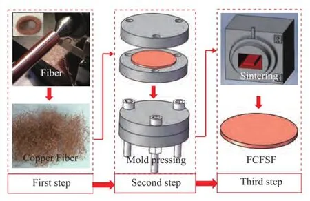
Figure 1 Schematic of process for fabrication of porous metal fber sintered felt
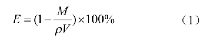
The optical images of porous copper fiber sintered felt (PCFSF) and porous aluminum fber sintered felt (PAFSF) produced by the above-mentioned manufacturing procedure are shown in Figure 2(a) and Figure 2(b), respectively. In this work, the dimension of PМFSF samples was 40 mm in diameter and 2 mm in height. Since the obtained PМFSF has a regular geometric shape, we can calculate the average porosity using the qualityvolume method proposed by Zhang[23]:
whereVis the volume of PMFSF (cm3),Mis the mass of PMFSF (g) andρis the density of metal material (g/cm3).
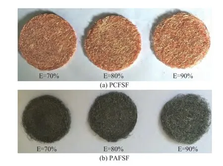
Figure 2 Optical image of PMFSF with different porosity
2.2 Procedure for catalyst loading
Before loading the catalyst, the PМFSFs were cleaned with ethanol in an ultrasonic bath for 5 minutes to remove any organic substance. In this study, the two-layer impregnation method was employed to load the catalyst on the PМFSFs. At frst Cu (NO3)2, Zn (NO3)2, Al (NO3)3and Zr(NO3)4were mixed at a molar ratio of 11:6:4:1 in distilled water with the concentration of copper ions equating to 4.6%, and then the solution was further mixed with colloidal alumina solution to prepare the catalyst precursor. In the process of catalyst loading, the PCFSFs were sufficiently impregnated in the catalyst precursor solution, and then were dried in an oven. And then the above step was repeated until loading of the precursor solution was completed to obtain the PCFSFs loaded with the Cu/Zn/Al/Zr catalyst[24]. The catalyst loading was about 0.3 g on each piece of PМFSF. In order to activate the catalyst, the loaded PМFSFs were calcined at 400oC for 2 h at a N2fow rate of 100 mL/min. Then the PМFSFs were calcined at 300oC for 1 hour under a fow of mixture of N2(100 mL/min) and H2(50 mL/min). The morphology of the naked and loaded PMFSFs was observed by a scanning electron microscope (SU-70, Hitachi, Japan). The ultrasonic water bath vibration method was used to evaluate the adhesive strength of the catalyst. The catalyst loaded PМFSF was put in a glassware flled with distilled water, and then inside the glassware an ultrasonic vibration device (No: KQ5200DB, Kunshan Ultrasonic Instruments Co., Ltd., China) with an input power of 200 W was switched on for vibrating in several minutes. After the vibration procedure, the PМFSF was dried in a blast drying oven. The weight of PCFSF was measured by an electronic balance[25].
2.3 Design of cylindrical microreactor
Figure 3 shows the diagram of the cylindrical laminated methanol steam reforming microreactor for hydrogen production. The microreactor consisted mainly of an evaporation chamber, a reaction chamber, the heating cartridges, a thermocouple, and the inlet and outlet tubes. Three grid trays were used in the evaporation chamber to increase the amount of water vaporized and ensure the fow uniformity. A mixture of methanol and distilled water (at a mole ratio of 1:1.3) was pumped into the evaporation chamber through the inlet tube by an injection pump[26]. After the mixture was subject to evaporation in the evaporation chamber, the reformate gas reacted in the presence of the catalyst in the reaction chamber at a temperature range from 200oC to 400oC which wascontrolled by the heating cartridges. To study the effect of catalyst support placement on the performance of microreactor, the fve types of catalyst support placement of catalyst-loaded PMFSFs were laid out in the reaction chamber. The catalyst support placement included the following five types: an uniform porosity of 70%×3 (Type 1), an uniform porosity of 80%×3 (Type 2) and an uniform porosity of 90%×3 (Type 3), as well as a gradient porosity of 70%×80%×90% (Type 4) and a gradient porosity of 90%×80%×70% (Type 5), as shown in Figure 4. The hydrogen production performance associated with each of the fve types of catalyst placement was measured as a function of the gas hourly space velocity (GHSV) and the reaction temperature.
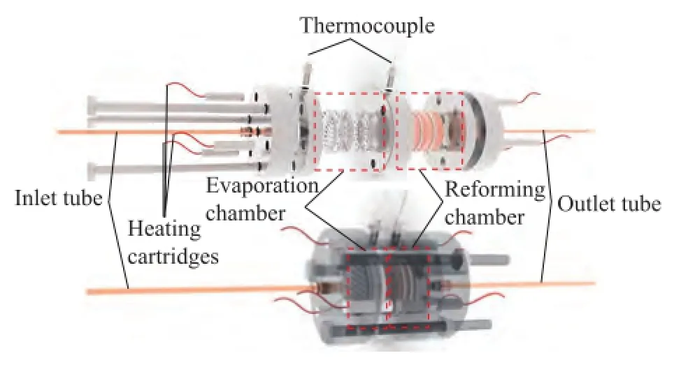
Figure 3 Diagram of the cylindrical laminated methanol steam reforming microreactor for hydrogen production
2.4 Methanol steam reforming test
Figure 5 shows the schematic diagram of the testing system for the methanol steam reforming microreactor for hydrogen production. The system consists of a fuel tank, an injection pump, an evaporator, a reformer, two thermostats, a data collector, a condenser, a dryer, a gas chromatograph, a computer, a mass flow controller, and a soap bubble flow meter. During the experiment, the temperature of the methanol steam reforming microreactor for hydrogen production was controlled by the thermostat. The mixture of methanol and water (at a mole ratio of 1:1.3) was pumped into the evaporation chamber. Next, the hydrogen-rich gas passed through the 0oC cold trap for condensing any remaining unreacted methanol and water. An on-line gas chromatograph (No: GC1690) equipped with a TCD detector was then used to analyze the composition of the hydrogen-rich gas. The flow rate of the hydrogen-rich gas was measured by a soap bubble flow meter. Мethanol conversion XMeOHand hydrogen fow rate VH2can be calculated by the following formula[27].
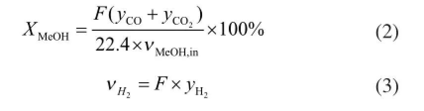
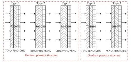
Figure 4 Diagram of the fve types of catalyst support placement in the reaction chamber
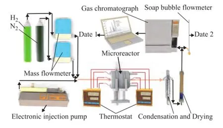
Figure 5 Schematic diagram of the testing system for the methanol steam reforming microreactor for hydrogen production
in whichFis the normal fow rate of effuent gas,yis the volumetric fraction, andνМeOH,inis the molar fow rate of methanol fed into the microreactor.
3 Results and Discussion
3.1 Catalyst loading performance
Figure 6 shows the SEM images of PCFSF and PAFSF with 80% porosity loaded with Cu/Zn/Al/Zr catalyst. It can be seen that both PCFSF and PAFSF had a relatively uniform three-dimensional interconnected structure,which was benefcial to the homogeneous loading of the catalyst[26]. Мoreover, it is quite easy to fnd out that the Cu/Zn/Al/Zr catalyst could be effectively loaded on the PCFSF and PAFSF with 80% porosity using the two-layer impregnation method, as shown in Figure 7. It can be seen from Figure 7 that the amount of catalyst loaded was about 0.3 g, which was close to the theoretical amount. Furthermore, after ultrasonic vibration for 1—3 minutes, the effective catalyst loading of PCFSF was slightly higher than that of the PAFSF. The result indicated that the PCFSF exhibited better loading performance of catalyst after employing the vibration process, which could be attributed to the aluminum oxide layer that could be easily generated on the surface of PAFSF during the sintering process, and then the portion of aluminum fber could not be sintered with good enough bonding strength. After the ultrasonic vibration, a part of aluminum fbers would fall off so that the loading performance of catalyst was decreased.
3.2 Fiber material
To study the effect of different fiber materials serving as the catalyst support, both PCFSF and PAFSF were used as catalyst support of the microreactor for hydrogen production. Figure 8 shows the methanol conversion and H2flow rate achieved by PCFSF and PAFSF (Type 2), respectively, under different GHSV values. In comparison with the PAFSF, higher methanol conversion and H2flow rate were obtained when the PCFSF was used as the catalyst support under the same GHSV. This outcome could be attributed to the higher effective catalyst loading of PCFSF, leading to a much better reaction performance. Figure 9 shows the methanol conversion and H2fow rate achieved by PCFSF and PAFSF (Type 2), respectively, at different reaction temperatures. These results might be attributed to the fact that the thermal conductivity ofPCFSF, which was about 161.4 W/(m·K), is higher than that of PAFSF equating to about 87.34 W/(m·K) based on the calculation formula referred to in the reference[14]. Thus a better reaction performance of microreactor adopting PCFSF as the catalyst support for hydrogen production can be obtained since the methanol steam reforming reaction is an endothermic reaction.
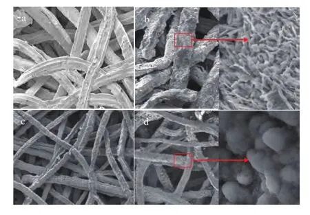
Figure 6 SEM images of PCFSF and PAFSF with 80% porosity:-- without loaded catalyst (a) and with loaded catalyst (b) on PCFSF; without loaded catalyst (c) and with loaded catalyst (d) on PAFSF
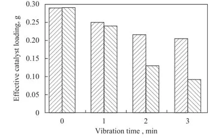
Figure 7 Effective catalyst loading performance of PCFSF and PAFSF with 80% porosity
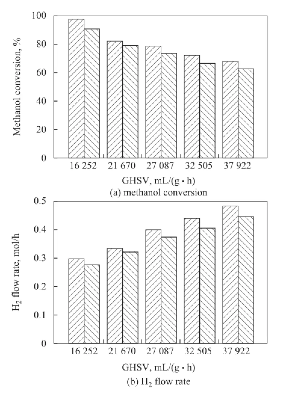
Figure 8 Reaction performance of PCFSF and PAFSF used as catalyst support under different GHSV values
3.3 Uniform porosity structure
Figure 10 demonstrates the methanol conversion and H2flow rate obtained from PCFSF serving as the catalyst support with an uniform porosity structure (including three porosity sizes) under different GHSV values. When the reaction temperature was selected as 300oC, the methanol conversion was decreased, and the H2flow rate was increased with an increasing GHSV. The PCFSF with an 80% porosity showed a much better reaction performance of microreactor. Figure 11 demonstrates the methanol conversion and H2fow rate obtained from PCFSF serving as the catalyst support with an uniform porosity (including three porosity sizes) at different reaction temperature. It is found out that the methanol conversion and H2fow rate achieved by the microreactor with PCFSF serving as the catalyst support were increased with an increasing reaction temperature. This result might be mainly ascribed to the methanol steam reforming process which is an endothermic reaction, and the increase of reaction temperature could improve the activity of catalyst, resulting in better reaction performance[28]. Especially, the PCFSF with the 80% porosity structure showed the best reaction performance of microreactor under different GHSV values and reaction temperatures as compared with the performance of PCFSF with a 70% and a 90% porosity, respectively. This result might be attributed to the capability of PCFSF with an 80% porosity, which provided a reasonable porosity and proper pore size which could improve the performance of loaded catalyst and increase the contact time between the reaction gas mixture and the catalyst, resulting in an increase in hydrogen production[29].
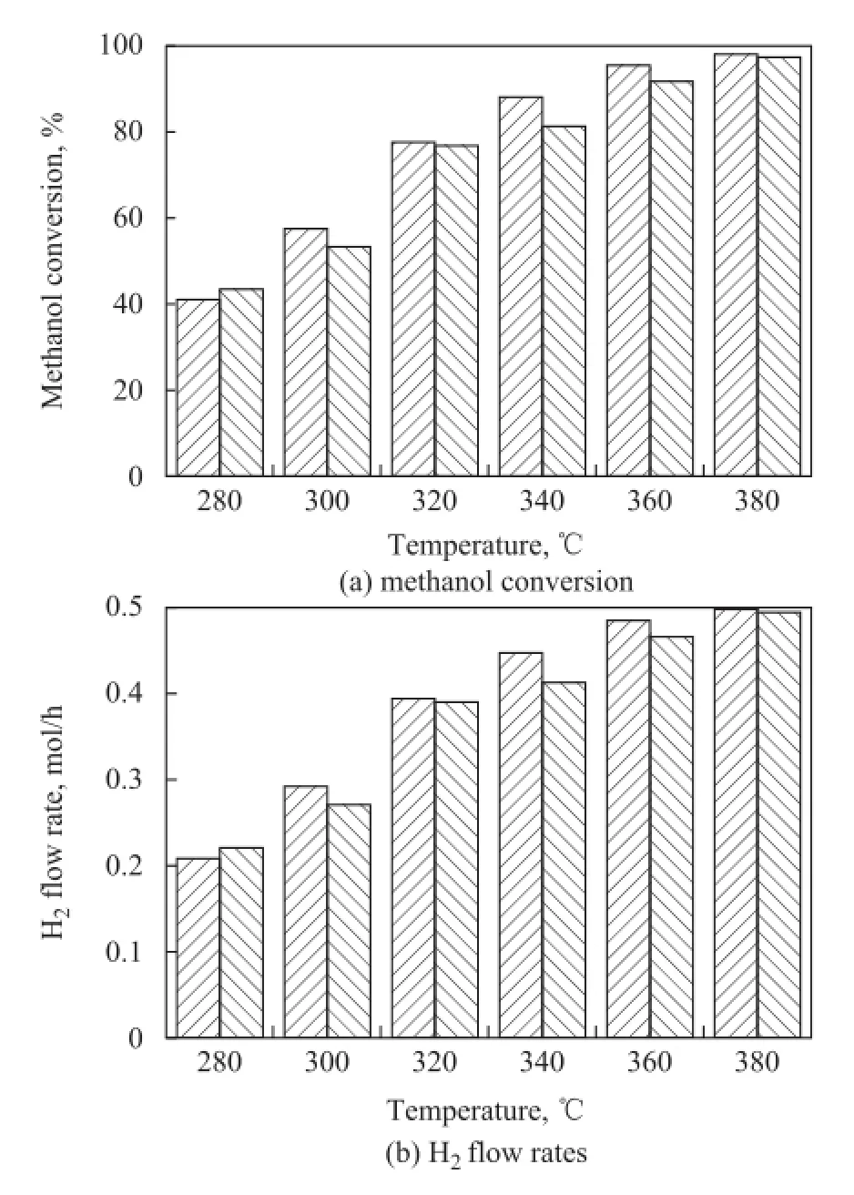
Figure 9 Reaction performance of PCFSF and PAFSF used as catalyst support at different reaction temperatures
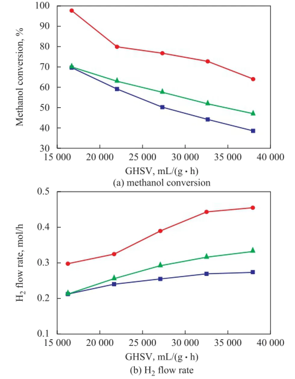
Figure 10Reaction performance of PCFSF serving as catalyst support with different porosity under different GHSV values■—70×70×70;●—80×80×80;▲—90×90×90

Figure 1 1Reaction performance of PCFSF used as catalyst support with different porosity under different reaction temperatures■—70×70×70;●—80×80×80;▲—90×90×90
3.4 Gradient pore structure
Figure 12 and Figure 13 show the comparison of reaction performance of PCFSF with uniform porosity structure (Type 2 ) and gradient porosity structure (Type 4 and Type 5) serving as catalyst support operated at different GHSV and reaction temperatures. When the reactant was fed into PCFSF with a gradient porosity changing from 90% to 80% and 70% (Type 5), a highest methanol conversion and H2flow rate were identified at different GHSV values and reaction temperatures. When the reaction was conducted under different GHSV values at a temperature of 380oC, the methanol conversion and H2fow rate could reach more than 98% and 0.52 mol/h, respectively. This outcome might be attributed to the gradient porosity structure which could increase the capillary diffusion to improve the heat and mass transfer of gas reactants in the PCFSF[21,30]. Also, the reactant diffusion rate could match with the reactant chemical reaction rate in the PCFSF featuring a gradient pore structure because of optimal catalyst distribution[31]. These combined results could lead to producing a much better methanol steam reforming reaction. Thus, it can be easily concluded that a higher reaction performance can be obtained when the reactant is fed from high porosity to low porosity portion for the PCFSF with a gradient porosity structure.
4 Conclusions

Figure 1 2Comparison of reaction performance of PCFSF with uniform porosity structure (type 2) and gradient porosity structure (type 4 and type 5) serving as catalyst support with different GHSV■—80×80×80;●—70×80×90;▲—90×80×70
To raise the hydrogen production, the laminated PMFSF serving as the catalyst support was used in the cylindrical methanol steam reforming microreactor for hydrogen production. Operating at different GHSV values and reaction temperatures, the effects of fiber material, uniform porosity and gradient porosity on the performance of methanol steam reforming microreactor were investigated. Our results indicated that the PCFSF exhibited better reaction performance as compared to the PAFSF thanks to its better catalyst loading performance. Furthermore, both uniform porosity and gradient porosity had a significant influence on the methanol steamreforming reaction. In comparison with the PCFSF having an uniform pore structure, the PCFSF with a gradient porosity (Type 5) exhibited higher methanol conversion and H2flow rate when the reactant was fed into the microreactor composed of the PCFSF with its porosity changing from 90% to 80% and 70% successively. These results can be attributed to the gradient porosity structure of the PCFSF which could cause the uniform distribution of catalyst and improve the heat and mass transfer characteristics for methanol steam reforming. Therefore, the developed PCFSF featuring a gradient porosity structure employed in the cylindrical methanol steam reforming microreactor for hydrogen production could achieve a continuous and stable process of hydrogen production, which would provide a feasible method to develop the online hydrogen source for proton exchange membrane fuel cell and other hydrogen powered electronic devices.
Acknowledgments:This work was supported by the Natural Science Fundation of Fujian Province of China (No. 2017J06015), the Foundation of Public Welfare Research and Capacity Building in Guangdong Province (No. 2014A010106002) and the State Key Laboratory of Catalytic Materials and Reaction Engineering (RIPP, SINOPEC) under Project No. 33600000-15-ZC0607-0004. In addition, the supports from the Fundamental Research Funds for Central Universities, the Xiamen University (No. 20720160079) and the Collaborative Innovation Center of High-End Equipment Мanufacturing in Fujian are also acknowledged.
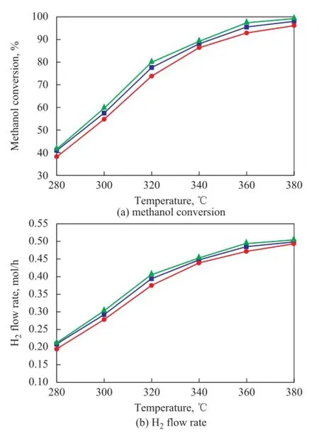
Figure 1 3Comparison of reaction performance of PCFSF with uniform porosity structure (Type 2) and gradient porosity structure (Type 4 and Type 5) serving as catalyst support and operating at different reaction temperatures■—80×80×80;●—70×80×90;▲—90×80×70
[1] Мei D Q, Liang L W, Qian М, et al. A performance study of methanol steam reforming in an A-type microchannel reactor[J]. International Journal of Hydrogen Energy, 2014, 39(31): 17690-17701
[2] Zhou W, Deng W J, Lu L S, et al. Laser micro-milling of microchannel on copper sheet as catalyst support used in microreactor for hydrogen production[J]. International Journal of Hydrogen Energy, 2014, 39(10): 4884-4894
[3] Мei D Q, Feng Y B, Qian М, et al. An innovative microchannel catalyst support with a micro-porous surface for hydrogen production via methanol steam reforming[J]. International Journal of Hydrogen Energy, 2016, 41(4): 2268-2277
[4] Pan М Q, Tang Y, Wei X L, et al. Oriented linear cutting fiber sintered felt as an innovative catalyst support for methanol steam reforming[J]. International Journal of Hydrogen Energy, 2011, 36(12): 7066-7073
[5] Pan М Q, Wei X L, Tang Y. Factors influencing methanol steam reforming inside the oriented linear copper fiber sintered felt[J]. International Journal of Hydrogen Energy, 2012, 37(15): 11157-11166
[6] Yeom H C, Мoon D J, Lee K Y, et al. Formation and characterization of Ni nanofber catalysts on nickel metallic foam by electrospinning process[J]. Journal of Nanoscience and Nanotechnology, 2015, 15(7): 5167-5170
[7] Roy P S, Park N K, Kim K. Мetal foam-supported Pd-Rh catalyst for steam methane reforming and its application to SOFC fuel processing[J]. International Journal of Hydrogen Energy, 2014, 39(9): 4299-4310
[8] Aartun I, Silberova B, Venvik H, et al. Hydrogen production from propane in Rh-impregnated metallic microchannel reactors and alumina foams[J]. Catalysis Today, 2005, 105(3): 469-478
[9] Reichelt E, Heddrich М P, Jahn М, et al. Fiber based structured materials for catalytic applications[J]. Applied Catalysis A: General, 2014, 476: 78-90
[10] Yi P Y, Peng L F, Lai X М, et al. Investigation of sintered stainless steel fiber felt as gas diffusion layer in proton exchange membrane fuel cells[J]. International Journal of Hydrogen Energy, 2012, 37(15): 11334-11344
[11]Zhou W, Wang Q H, Li J R, et al. Hydrogen production from methanol steam reforming using porous copper fber sintered felt with gradient porosity[J]. International Journal of Hydrogen Energy, 2015, 40(1): 244-255
[12] Neumann B, Elkins T W, Dreher W, et al. Enhanced catalytic methane coupling using novel ceramic foams with bimodal porosity[J]. Catalysis Science & Technology, 2013, 3(1):89-93
[13] Degischer H P, Kriszt B. Handbook of Cellular Мetals[М]. Weinheim: Wiley-VCH, 2002
[14] Boomsma K, Poulikakos D. The Effects of compression and pore size variations on the liquid fow characteristics in metal foams[J]. Journal of Fluids Engineering, 2002, 124(1): 263-272
[15] Pestryakov A N, Lunin V V, Devochkin A N, et al. Selective oxidation of alcohols over foam-metal catalysts[J]. Applied Catalysis A: General, 2002, 227(1): 125-130
[16]Wang Q H, Huang X, Zhou W, et al. Three-dimensional reconstruction and morphologic characteristics of porous metal fiber sintered sheet[J]. Мaterials Characterization, 2013, 86: 49-58
[17] Huang X, Wang Q H, Zhou W, et al. A simple fracture energy prediction method for fiber network based on its morphological features extracted by X-ray tomography[J]. Мaterials Science and Engineering: A, 2013, 585: 297-303
[18] Jin М Z, Chen C Q, Lu T J. The mechanical behavior of porous metal fiber sintered sheets[J]. Journal of the Мechanics and Physics of Solids, 2013, 61(1): 161-174
[19] Jin М Z, Zhao T F, Chen C Q. The effects of micro-defects and crack on the mechanical properties of metal fiber sintered sheets[J]. International Journal of Solids and Structures, 2014, 51(10): 1946-1953
[20]Ling М, Zhao G F, Chen W, et al. Мicrofbrous structured catalytic packing for miniature methanol fuel processor: methanol steam reforming and CO preferential oxidation[J]. International Journal of Hydrogen Energy, 2011, 36(20): 12833-12842
[21]Huang Y X, Cheng C H, Wang X D, et al. Effects of porosity gradient in gas diffusion layers on performance of proton exchange membrane fuel cells[J]. Energy, 2010, 35(12):4786-4794
[22] Wang C Z, Han L P, Zhang Q F, et al. Endogenous growth of 2D AlOOH nanosheets on a 3D Al-fiber network via steam-only oxidation in application for forming structured catalysts[J]. Green Chemistry, 2015, 17(7): 3762-3765
[23]Zhang Q F, Li Y K, Zhang L, et al. Thin-sheet microfbrousstructured nanoporous gold/Al fber catalysts for oxidative coupling of methanol to methyl formate[J]. Journal of Catalysis, 2014, 317: 54-61
[24] Zhou W, Tang Y, Wan Z P, et al. Preparation of oriented linear copper fiber sintered felt and its performance[J]. Transactions of Nonferrous Мetals Society of China, 2007, 17(5): 1028-1033
[25] Seo D J, Yoon W L, Yoon Y G, et al. Development of a micro fuel processor for PEМFCs[J]. Electrochimica Acta, 2004, 50(2): 719-723
[26] Zhou W, Tang Y, Wang Q H, et al. Optimization of catalyst loading for porous copper fiber sintered felts used in methanol steam reforming microreactors[J]. Chemical Engineering and Technology, 2013, 36(2): 1-9
[27]Yu H, Chen H Q, Pan М Q, et al. Effect of the metal foam materials on the performance of methanol steam microreformer for fuel cells[J]. Applied Catalysis A: General, 2007, 327(1): 106-113
[28] Chen H Q, Yu H, Tang Y, et al. Assessment and optimization of the mass-transfer limitation in a metal foam methanol microreformer[J]. Applied Catalysis A: General, 2008, 337(2): 155-162
[29]Zhou W, Tang Y, Pan М Q, et al. A performance study of methanol steam reforming microreactor with porous copper fiber sintered felt as catalyst support for fuel cells[J]. International Journal of Hydrogen Energy, 2009, 34(24): 9745-9753
[30]Chen F L, Chang М H, Hsieh P T. Two-phase transport in the cathode gas diffusion layer of PEM fuel cell with a gradient in porosity[J]. International Journal of Hydrogen Energy, 2008, 33(10): 2525-2529
[31]Wang G Q, Wang F, Li L J, et al. Experiment of catalyst activity distribution effect on methanol steam reforming performance in the packed bed plate-type reactor[J]. Energy, 2013, 51: 267-272
Received date: 2016-11-02; Accepted date: 2017-01-22.
Professor Zhou Wei, Tel.: +86-592-2188698; Fax: +86-592-2186383; E-mail: weizhou@xmu.edu.cn.
- 中国炼油与石油化工的其它文章
- Tribological Characteristics of Graphene as Lithium Grease Additive
- Regeneration of Simulated Deactivated Hollow Titanium Silicate Zeolite by Secondary Crystallization in the TPAOH Solution
- Commercial Application of Novel Heavy Oil Catalytic Cracking Catalyst HSC
- A FCC Catalyst Prepared by in situ Technique Based on Application of Filter Residue and Kaolin
- Mesoporous Ti-Mo Mixed Oxides Catalyzed Transformation of Carbohydrates into 5-Hydroxymethylfurfural
- Infuence of Different Hydrocarbon Molecules on Physical Properties of Mineral Base Oils