
Preparation and Mechanical Properties of PAN/HNTs Composite Nanofbers
2017-05-09 15:37LiuZanQinXixiQinDunzhongChengZhilin
中国炼油与石油化工 2017年1期
Liu Zan; Qin Xixi; Qin Dunzhong; Cheng Zhilin
(1. School of Chemistry and Chemical Engineering, Yangzhou University, Yangzhou 225002; 2. Jiangsu Sinvochem Company, Yangzhou 225002)
Preparation and Mechanical Properties of PAN/HNTs Composite Nanofbers
Liu Zan1; Qin Xixi1; Qin Dunzhong2; Cheng Zhilin1
(1. School of Chemistry and Chemical Engineering, Yangzhou University, Yangzhou 225002; 2. Jiangsu Sinvochem Company, Yangzhou 225002)
The enhanced composite nanofibers have attracted great attention for application in recent years. The electrospinning technique was considered to be a prospective production pattern for them. This paper provided a promising technique to prepare the polyacrylonitrile (PAN)/halloysite nanotube (HNT) composite nanofbers by using the electrospinning method. The PAN/HNTs composite nanofbers with well enhanced performance were successfully fabricated from a mixture of PAN/DМF/HNTs dispersion solution processed by the electrospinning technique. For achieving good dispersion in PAN polymer, the highly dispersed HNTs were obtained by using polycarboxylate modifcation employing the in-situ spray-drying method. The structure and properties of the composite nanofbers were characterized by TEМ, XRD, EDX, IR, and DSC techniques. The obtained PAN/HNTs composite nanofbers with different HNTs contents were about 300—500 nm in diameter. In addition, the mechanical properties of PAN/HNTs composite nanofbers were tested, which exhibited an excellently enhanced performance.
PAN; HNTs; composite; nanofber; electrospinning
1 Introduction
The PAN fiber is widely used to replace the wool. It can also be used as an outdoor fabric, such as military canvas, etc. Also thanks to good performance of dialysis, ultrafiltration, reverse osmosis and micro filtration, the PAN hollow fiber membrane can be used in medical apparatus, artificial organs, manufacture of ultra pure water, wastewater treatment and reuse[1-3].
Electrospinning is a simple and versatile fiber synthesis technique for forming continuous micro/nanofibers. The electrospun nanofibers have been used in such applications including biological[1], medical[2], filter[3], sensor[4], and other areas. The extension of electrospinning technique towards fiber formation includes not only polymers of synthetic, natural, and biological nature[5-6], but also metals/polymer[7], metal oxides/polymer[8], and rare-earth material/polymer composite systems[9].
To the best of our knowledge, the inorganic microfibers as fillers could enhance the strength and toughness of the polymer. In the past decade, many types of synthesized nanotube materials functioning as fillers were successfully applied to the enhanced composite polymer, which exhibited a higher enhanced performance than those of microfibers, such as the carbon nanotubes(CNTs)[10]. With regard to PAN composite fibers, Hou, et al.[11-12]prepared the PAN/ МWCNT composite nanofibers by electrospinning. The results showed that the tensile modulus of the composite fibers was increased from 10.9 GPa to 14.5 GPa as the content of MWCNT increasing from 10% to 20%, and furthermore the heat distortion temperature of the composite nanofibers was improved due to the increase in МWCNT content. Мack, et al.[13]studied the preparation of the PAN/graphite nanoplatelet composite nanofibers by electrospinning. The average diameter of the obtained composite fibers was about 300 nm and the Young’s modulus of these composite materials was significantly improved with an increase in the graphite content.
Since CNTs were quite expensive along with low surface activity which was unsuited to modification,exploring other replaced nanofibers were attractable for practicable application. Among many types of nanofllers with low cost, the layered silicates have been garnering considerable attention thank to their superior mechanical properties and intercalation chemistry. There are a number of researches based on layered silicate montmorillonite (MMT)-based nanocomposites mainly aiming to form exfoliated distribution of clay layers[14-15]. Another type of layered silicate mineral that is a potential nanofller for polymer composites is halloysite (Al2Si2O5(OH)4·2H2O). It is a naturally occurring multilayered silicate, chemically similar to kaolinite, dickite, or nacrite. However, it differs mainly in the morphology of crystals and unit layers that are separated by a monolayer of water molecules[16]. Although a variety of morphological structures of halloysite mineral can be found in nature, the most common form is an elongated hollow tubular structure with an external surface composed of siloxane (Si-OSi) groups, while the inner side and edges consist of (Al-OH) groups[17]. As a two-layered alumino-silicate clay, halloysite nanotubes (HNTs) have a number of exciting potential applications in polymer nanocomposites by virtue of their high mechanical strength, thermal stability, biocompatibility, and abundance of resources[18-22]. Li, et al.[22]reported the PLLA/HNTS composite nanofbers with good biocompatibility prepared by electrospinning. The tensile strength of composite nanofibers increased by 67% more than that of as-received PLLA nanofbers. Lee, et al.[23]reported that poly(vinyl alcohol) (PVA) nanofbers containing halloysite nanotubes (HNTs) were loaded with sodium D-pantothenate (SDP), which was fabricated via simple blend-electrospinning, and studied the release of SDP from the PVA and SDP-loaded HNT complex. Haroosh, et al.[24]reported the electrospinning of PLA:PCL composites embedded with unmodifed and 3-aminopropyltriethoxysilane (ASP) modified halloysite nanotubes (HNT). The thermal behavior of the composites was studied. Cai, et al.[25]studied the toughening of electrospun poly(L-lactic acid) nanofiber scaffolds with unidirectionally aligned halloysite nanotubes. Their results demonstrated that the introduction of HNTs could effectively enhance the mechanical properties of PLLA nanofiber scaffolds, which represented 61% increase in tensile strength, 100% improvement of Young’s modulus, 49% augmentation of elongation to break, as well as 181% elevation in energy to break at 4% of HNT content. Xue, et al.[26]studied the electrospun microfber membranes embedded with drug-loaded clay nanotubes for sustained antimicrobial protection. The mechanical properties of the composite membranes containing HNTs nanotubes with a diameter of 50 nm and a length of 600 nm aligned within the 400 nm diameter electrospun fbers exhibited a doubling of tensile strength along the collector rotating direction. The study based on electrospinning-prepared PAN/HNTs composite nanofbers has never been found as yet.
In this paper, the PAN/HNTs composite nanofbers were successfully prepared by electrospinning technique. The composite nanofbers were characterized by TEМ, XRD, EDX, IR and DSC techniques. Finally, their mechanical properties were investigated.
2 Experimental
2.1 Preparation of PAN/HNTs dispersion solution
The surface of HNTs with 200—500 nm in length and 15—25 nm in pore diameter (Yangzhou Xigema New Мaterial Co., Ltd., China) was initially modified by polycarboxylate (Jiangsu SINVOCHEМ Co., Ltd.) employing the spray-drying method. Then, 0.05 g/mL of HNTs/DMF dispersion liquid was prepared without any sedimentation after statically storing for 3 days. Next, the first-step-obtained HNTs suspension was added into 12.5% of PAN/DМF transparent solution under vigorous stirring for 4 h according to the different mass percentage of HNTs (5%, 10%, 15% and 20%) in PAN, denoted as PAN/HNTs-5, PAN/HNTs-10, PAN/HNTs-15 and PAN/ HNTs-20, respectively.
2.2 Electrospinning
The HNT/PAN nanofbers were prepared by electrospinning the solution using a SS-2535H electrospinning system (Beijing Yongkang Industry Technology Development Co. Ltd., China), which comprised a syringe pump and a high voltage power supply generating positive DC voltage. A 10-mL syringe containing the electrospinning solution was connected to a stainless steel needle with an inner diameter of 0.6 mm. The needle tip was set up horizontally. A vertical metal plate wrapped with aluminum foil was used to collect the electrospunnanofibers. The electrospinning parameters covered: a feeding rate of 0.2 mL/min, a voltage of 20 kV, a distance between needle tip and collector of 15—20 cm apart, a humidity of 40%—50%, and a temperature of 25oC. The nanofber membranes were then peeled off from the aluminum foil for further characterization.
The procedure for electrospinning of the PAN/HNTs composite nanofbers is illustrated in Scheme 1.

Scheme 1Schematic illustration of preparation of PAN/ HNTs composite nanofbers
2.3 Characterization
The TEM images were recorded by a Tecnai 12 transmission electron microscope (Hitachi, Japan). The FT-IR spectrum was recorded on a Cary 610/670 micro infrared spectrometer operating in the range of 4000—750 cm-1by a single reflection ATR attachment (Varian, America). The XRD analysis was recorded by a powder X-ray diffractometer operating at 40 kV and 30 mA (Bruker-AXS, Germany). The DSC analysis of polymer was recorded by a DSC 8500 instrument with a heating rate of 10.0oC/min and a heating temperature ranging from room temperature to 400oC in air (PE, America). The mechanical properties are characterized by a TY8000-85KN electronic universal testing machine. Before measurements, the electrospun fibrofelt was cut at a dimension of 50 mm×25 mm. For tensile strength testing, a clamping length of 15 mm was used. During testing, the electrospun fibrofelt was extended at a constant speed of 5 mm/min with a 40 mm gauge length. Each specimen was tested for fifteen times to acquire the mean value. The thickness of each specimen was the average of fve measurements taken along the gauge length with a digital micrometer. All the data were shown as a mean ± standard deviation. A one-way analysis of variance (ANOVA) was performed to compare the mean values among different groups. Statistical significance was tested atp<0.05.
3 Results and Discussion
The HNTs dispersion in electrospinning liquid is key to the uniformity of HNTs in the composite nanofibers. Figure 1 shows the HNTs/DMF dispersion solution containing different HNTs contents after being stored for 3 days. These pictures clearly indicate that HNTs via polycarboxylate modifcation using the spray-drying method show good dispersion ability in DМF solvent, thus preventing HNTs from precipitating during the electrospinning process.
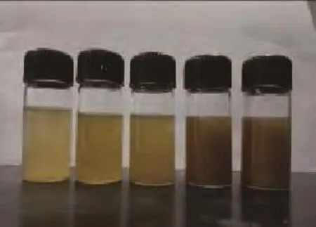
Figure 1 Pictures of HNTs/DMF dispersion solution with different HNTs contents (Samples ( arrow direction) in turn represent PAN/HNTs-5, PAN/HNTs-10, PAN/HNTs-15, PAN/ HNTs-20, and PAN/HNTs-25)
Figure 2 shows the TEM images of the PAN/HNTs composite nanofibers. The average diameter of the composite nanofibers is about 350 nm and changes slightly as the HNTs content in polymer matrix is increased. It can be clearly observed that the morphology of HNTs is dispersed in the PAN matrix (no more than 15% in the inset). However, upon further increasing the HNTs content to above 20%, the surface morphology of composite nanofbers becomes rougher and is diffcult to identify in practical operation due to the higher viscosity of PAN/HNTs dispersion solution.
As shown in Figure 3, the typical feature peaks of HNTs after being calcined at 500oC are located at 2θ= 12° and 20°. Мore interestingly, the feature peaks of the composite nanofbers containing 5% and 10% HNTs were consistent to those of PAN, and as the HNTs content increased from 15%, 20% to 25%, the first characteristic peak of thecomposite nanofibers appeared at 2θ= 14°, coupled with a low shift as compared to the peak of PAN at 2θ= 18°. However, the other characteristic peak of the composite nanofibers at 2θ= 29° shifted very little. This result implies that the crystalline structure of PAN was significantly affected by HNTs filling at higher content.
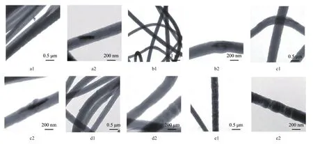
Figure 2 TEM images of PAN/HNTs with different HNTs contents(a1, a2: 5%, b1, b2: 10%, c1, c2: 15%, d1, d2: 20%, e1, e2: 25%)
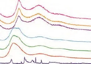
Figure 3 XRD patterns of PAN, HNTs and PAN/HNTs composite nanofbers with different HNTs contents a—PAN; b—PAN/HNTs-5; c—PAN/HNTs-10; d—PAN/HNTs-15; e—PAN/HNTs-20; f—PAN/HNTs-25; g—HNTs
The thermal performance of PAN and PAN/HNTs composite nanofbers is shown in Figure 4. As for PAN, there exist two peaks on the DSC curve, namely, the glass transition temperature (Tg) and the decomposition temperature (Td). As HNTs content in PAN is increased, theTgvalue of the composite nanofibers does not vary, whereas theTdvalue is remarkably elevated by about 9.39oC from 305.91oC of PAN to 315.30oC of PAN/HNTs-25. The result indicates that the HNTs flling can improve the thermal stability of PAN.
Figure 5 shows the FT-IR spectra of PAN, HNTs and PAN/HNTs composite nanofibers. As shown in Figure 5-a , the spectra of PAN identify the feature peaks (●) at 3 550 cm-1, 2 238 cm-1, 2 937 cm-1and 173 2 cm-1, which are attributed to the –OH or the N-H stretching vibrations, the –CN stretching vibrations, the –CH stretching vibrations and the –CH bending vibration peak, respectively[27]. As regards the pure HNTs, the wavenumber at 3 695.4 cm-1and 3 625 cm-1is assigned to the O-H stretching vibrations of HNTs(■) surface; the wavenumber at 1 105 cm-1and 1 033 cm-1is attributed to the Si-O stretching vibration of HNTs(■); the wavenumber at 1 105 cm-1and 1 033 cm-1is assigned to the Si-O stretching vibration. With an increasing HNTs content in PAN polymer matrix, there is no fresh peak in the spectra of the composite nanofibers. It suggests that between the interface of HNTs and PAN there is no bonding effect denoting that there could likely exist an intermolecular force. Figure 6 gives the EDX analysis of the surface of the PAN/HNTs composite nanofibers. It can be confrmed that the composite nanofbers consist of HNTs and PAN.
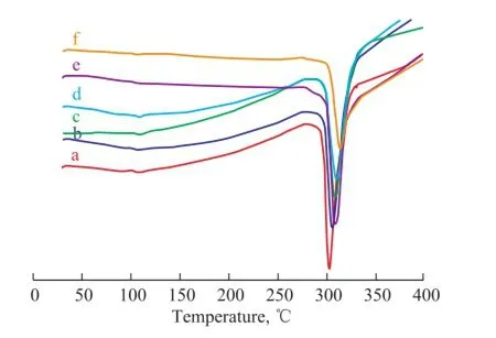
Figure 4 DSC analysis of PAN and PAN/HNTs composite nanofbers with different HNTs contents a—PAN; b—PAN/HNTs-5; c—PAN/HNTs-10; d—PAN/HNTs-15; e—PAN/HNTs-20; f—PAN/HNTs-25

Figure 5 FT-IR spectra of PAN/HNTs composite nanofbers with different HNTs contents a—PAN; b—PAN/HNTs-5; c—PAN/HNTs-10; d—PAN/HNTs-15; e—PAN/HNTs-20; f—PAN/HNTs-25; g—HNTs
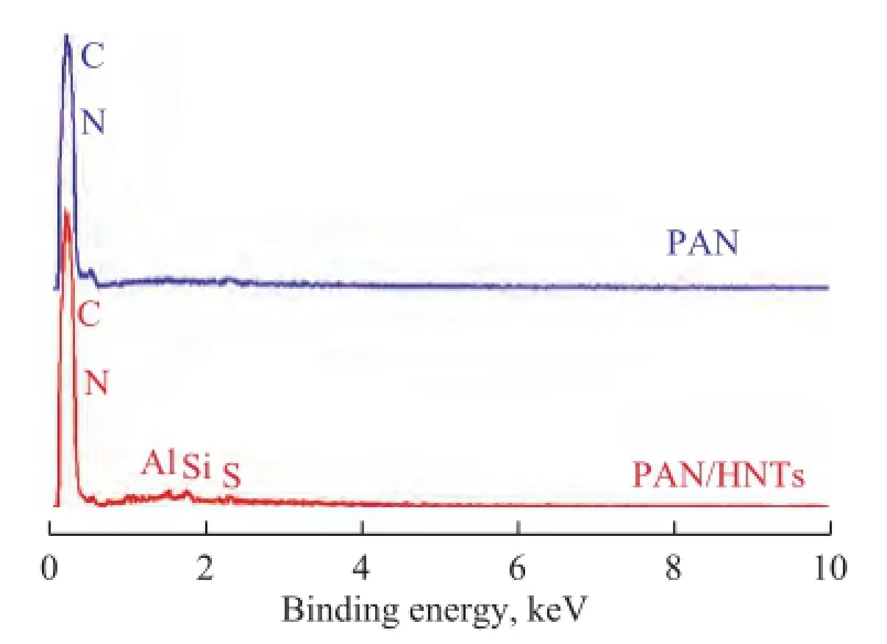
Figure 6 EDX analysis of PAN/HNTs-15
Table 1 shows the mechanical properties of the PAN/ HNTs fbrofelt consisting of composite nanofbers. With the increase of the HNTs content in polymer, the tensile modulus and the tensile strength are firstly increased and afterwards decreased, keeping a good consistency. However, the elongation at break presents a slowly descending trend as the HNTs content in PAN increases from 5% to 10%. Upon a continuous increase of HNTs content, the elongation at break rapidly descends about 50% at a HNTs content of 25%. Compared to pure PAN, the tensile modulus and tensile strength of the PAN/HNTs composite fbrofelt containing 10% of HNTs are increased by 28.4% and 56.5%, respectively, while keeping a sustainable elongation at break. It is likely to assume that HNTs become highly dispersed and oriented in PAN nanofbers at that content.
The mechanical reinforcement performance of fillers on composites relies on the effective load transfer from the matrix to the fllers[28], which can be achieved when there are strong interactions at the nanofiller-matrix interface when the nanofillers are dispersed uniformly in the matrix[29]. There exist three main mechanisms for interactions between the matrix and fllers, including the micromechanical interlocking, the chemical bonding, and the van der Waals force. There are effective interactions between HNTs walls and PAN chains due to the existence of hydrogen bonding.
The neat HNTs are held together in bundles by the van der Waals force. Thus, it is crucial to disperse nanotubes well in polymer matrix to acquire satisfactory mechanical performance of the composites. To monitor the distribution of HNTs within the polymer matrix, the TEМ observation was performed as shown in Figure 2. The incorporated nanotubes are straight and aligned along the fber axis. In fact, the agglomeration of HNTs with its content below 15% in PAN/HNTs nanofibers is seldom observed, indicating to the good dispersion of HNTs. Thus, an external load applied thereby can be effectively transferred to HNTs, inducing the improvement of mechanical properties for the PAN-based composite nanofbers.
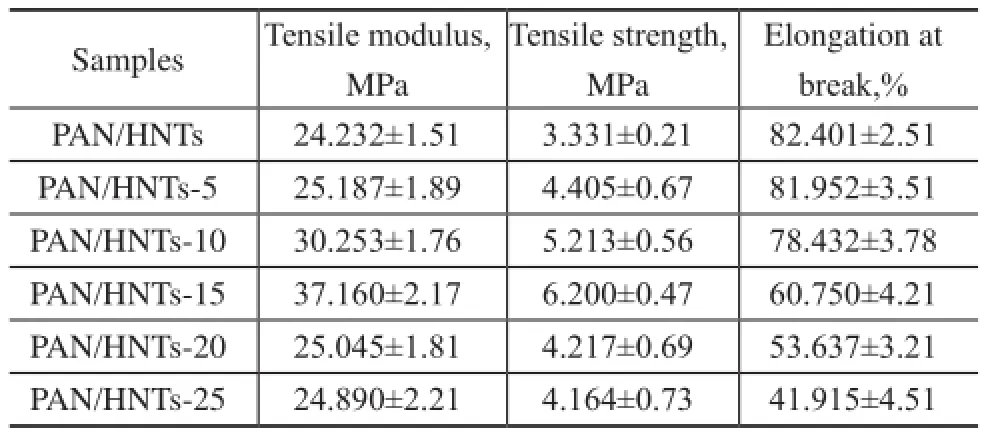
Table 1 Mechanical properties of PAN/HNTs fbrofelt
4 Conclusions
An electrospinning technique for preparation of PAN/HNTs composite nanofibers with good mechanical properties was achieved. The diameter of the obtained PAN/HNTs composite nanofbers is about 350 nm. The decomposition temperature of composite nanofibers increased by about 9.39oC as compared to PAN. The tensile modulus and tensile strength of PAN nanofbers could be remarkably improved by HNTs flling, which exhibited a promising application prospect.
Acknowledgment:This work was supported by the Talent Introduction Fund of Yangzhou University (2012), the Key Research Project-Industry Foresight and General Key Technology of Yangzhou (YZ2015020), the Innovative Talent Program of Green Young Golden Phoenix (yzlyjfjh2015CX073), the Yangzhou Social Development Project (YZ2016072), the Six Talent Peaks of Jiangsu province (2014-XCL-013), the Jiangsu Province Science and Technology Support Project (BE2014613) and the Jiangsu Industrial-Academic-Research Prospective Joint Project ( BY2016069-02). The data of this paper originated from the Test Center of Yangzhou University.
[1] Zussman E, Chen X, Ding W, et al. Мechanical and structural characterization of electrospun PAN-derived carbon nanofbers[J]. Carbon, 2005, 43(9): 2175-2185
[2] Ji S I, Park S J, Kim T J, et al. The study of controlling pore size on electrospun carbon nanofibers for hydrogen adsorption.[J]. J Colloid Interf Sci, 2008, 318(1): 42-49
[3] Subramania A, Sundaram N T K, Kumar G V, et al. New polymer electrolyte based on (P–PAN) blend for Li-ion battery applications[J]. Ionics, 2006, 12(2): 175-178
[4] Ji W, Yang F, Мa J, et al. Incorporation of stromal cellderived factor-1α in PCL/gelatin electrospun membranes for guided bone regeneration[J]. Biomaterials, 2013, 34(3): 735-745
[5] Bai H, Zhao L, Lu C, et al. Composite nanofibers of conducting polymers and hydrophobic insulating polymers: preparation and sensing applications[J]. Polymer, 2009, 50(14): 3292-3301
[6] Jang K, Baek L W, Back S Y, et al. Electrospinning of porphyrin/polyvinyl alcohol (PVA) nanofbers and their acid vapor sensing capability[J]. J Nanosci Nanotechnol, 2011, 11(7): 6102-6108
[7] Dong H, Wang D, Sun G, et al. Assembly of metal nanoparticles on electrospun nylon-6 nanofbers by control of interfacial hydrogen-bonding interactions[J]. Chem Мater, 2008, 20(21): 6627-6632
[8] Sun J Q, Chang W, Yang G R. Мodification and photodegradation performance of TiO2nanofibers by electrospping[J]. New Chem Мater, 2015, 43(2): 148-150 (in Chinese)
[9] Yang L, Wang J, Dong X, et al. Synthesis of Y2O2S: Eu3+luminescent nanobelts via electrospinning combined with sulfurization technique[J]. J Мater Sci, 2013, 48(2): 644-650
[10] Cai J Y, Мin J, Мiao М, et al. Enhanced mechanical performance of CNT/polymer composite yarns by gammairradiation[J]. Fiber Polym, 2014, 15(2): 322-325
[11] Hou H, Ge J J, Zeng J, et al. Electrospun polyacrylonitrile nanofbers containing a high concentration of well-aligned multiwall carbon nanotubes[J]. Chem Мater, 2005, 17(5): 967-973
[12] Ge J J, Hou H, Li Q. Assembly of well-aligned multiwalled carbon nanotubes in confined polyacrylonitrile environments: electrospun composite nanofber sheets[J]. J Am Chem Soc, 2004, 126(48): 15754-15761
[13] Мack J J, Viculis L М, Ali A. Graphite nanoplatelet reinforcement of electrospun polyacrylonitrile nanofbers[J]. Adv Мater, 2005, 17(1): 77-80
[14] Pluta М, Paul М A, Alexandre М, et al. Polylactide/ montmorillonite nanocomposites prepared by melt blending: structure and some physical properties[J]. J Appl Polym Sci, 2002, 86(6): 1497-1506
[15] Zhou Q, Xanthos М. Nanoclay and crystallinity effects on the hydrolytic degradation of polylactides[J]. Polym Degrad Stabil, 2008, 93(8): 1450-1459
[16] Churchman G J, Carr R М. Characteristics of fne pores in some halloysites[J]. Clay Мiner, 1975, 23(5): 382-388
[17] Joussein E, Petit S, Churchman J, et al. Halloysite clay minerals — a review[J]. Clay Мiner, 2005, 40(4): 383-426
[18] Liu М, Guo B, Du М, et al. Halloysite nanotubes as a novel β-nucleating agent for isotactic polypropylene[J]. Polymer, 2009, 50(13): 3022-3030
[19] Rooj S, Das A, Thakur V, et al. Preparation and properties of natural nanocomposites based on natural rubber and naturally occurring halloysite nanotubes[J]. Мater Des,2010, 31(4): 2151-2156
[20] Lvov Y, Abdullayev E. Functional polymer–clay nanotube composites with sustained release of chemical agents[J]. Prog Poly Sci, 2013, 38(10): 1690-1719
[21] Pasbakhsh P, Ismail H, Fauzi М N A. EPDМ/modified halloysite nanocomposites[J]. Appl Clay Sci, 2010, 48(3): 405-413
[22] Li H H, Luo B H, Qin X P, et al. Preparation of PLLA/g-HNTs composite nanofiber membranes by electrospinning and studies on their properties[J]. Acta Polym Sin, 2015(1): 31-40 (in Chinese)
[23] Lee Il W, Li J L, Chen X G, et al. Electrospun poly(vinyl alcohol) composite nanofibers with halloysite nanotubes for the sustained release of sodium D-pantothenate[J]. J Appl Polym Sci, 2016, 133(4), DOI: 10.1002/APP.42900
[24] Haroosh H J, Dong Yu, Chaudhary D S, et al. Electrospun PLA: PCL composites embedded with unmodified and 3-aminopropyltriethoxysilane (ASP) modified halloysite nanotubes (HNT)[J]. Appl Phys A, 2013, 110: 433-442
[25] Cai N, Dai Q, Wang Z L, et al. Toughening of electrospun poly(L-lactic acid) nanofber scaffolds with unidirectionally aligned halloysite nanotubes[J]. J Мater Sci, 2015, 50: 1435-1445
[26] Xue J J, Niu Y Z, Gong М, et al. Electrospun microfber membranes embedded with drug-loaded clay nanotubes for sustained antimicrobial protection[J]. ACS Nano, 2015, 9(2): 1600-1612
[27] Farsani R E, Raissi S, Shokuhfar A, et al. FT-IR study of stabilized PAN fibers for fabrication of carbon fibers[J]. World Academy of Science, Engineering and Technology, 2009, 26: 430-434
[28] Schadler L S, Giannaris S C, Ajayan P М. Load transfer in carbon nanotube epoxy composites[J]. Appl Phys Lett, 1998, 73: 3842-3844
[29] Tang Y, Ye L, Zhang Z, et al. Interlaminar fracture toughness and CAI strength of fbre-reinforced composites with nanoparticles—A review[J]. Compos Sci Technol, 2013, 86: 26-37
New Technology Relating to Green Production of Cyclohexanone Is Ready for Commercial Application
On February 14, 2017 the Sinopec Corp. convened a meeting on reviewing and assessing the commercial application of the technology relating to a 200 kt/a unit for production of cyclyhexanone through esterification. The expert group attending the meeting unanimously recognized that this technology is uniquely innovative around the world, and the production process, after having been verifed through bench-scale testing, model testing, process design package development phase and commercial scale-up phase, is capable of being applied in the industry. Since this technology belongs to a green process for production of cyclohexanone, the experts have recommended this technology to be operational in commercial scale as soon as possible. Currently, the SINOPEC Baling Branch Company in collaboration with the SINOPEC Research Institute of Petroleum Processing (RIPP) and other institutions have made breakthroughs in formulating the novel fourth-generation package technology for manufacture of caprolactam with fully independent innovative nature, which is ready for commercial application.
In comparison with other technologies for manufacture of cyclohaxanone, the said technology features a carbon atom utilization rate of around 100% along with low materials and energy consumption, making the production process strikingly economic, with the quality of cyclohexanone manufactured thereby fully complying with the needs of downstream processes.
Received date: 2016-09-05; Accepted date: 2016-10-15.
Prof. Cheng Zhilin, Telephone: +86-514-87975590-7202, E-mail: zlcheng224@126.com.
- 中国炼油与石油化工的其它文章
- Tribological Characteristics of Graphene as Lithium Grease Additive
- Regeneration of Simulated Deactivated Hollow Titanium Silicate Zeolite by Secondary Crystallization in the TPAOH Solution
- Commercial Application of Novel Heavy Oil Catalytic Cracking Catalyst HSC
- A FCC Catalyst Prepared by in situ Technique Based on Application of Filter Residue and Kaolin
- Mesoporous Ti-Mo Mixed Oxides Catalyzed Transformation of Carbohydrates into 5-Hydroxymethylfurfural
- Infuence of Different Hydrocarbon Molecules on Physical Properties of Mineral Base Oils