
Analysis of sliding electric contact characteristics in augmented railgun based on the combination of contact resistance and sliding friction coefficient
2020-07-02 03:16ChunyanZhuBaomingLi
Defence Technology 2020年4期
Chun-yan Zhu, Bao-ming Li
National Key Laboratory of Transient Physics, Nanjing University of Science and Technology, China
Keywords:Augmented railgun Contact resistance Friction coefficient Contact characteristics
ABSTRACT The contact resistance between the armature and rails is an important indicator of the contact characteristics in electromagnetic launches.As the contact resistance depends not only on the contact state but also on the contact stress and temperature, there are some limitations in analyzing the contact characteristics using only the contact resistance. In this paper, the contact characteristics of the augmented railgun are analyzed by the combination of contact resistance and sliding friction coefficient. Firstly, the theoretical calculation model of the contact resistance and friction coefficient of the augmented electromagnetic railgun is established. Then the contact resistance and friction coefficient are calculated by the measured values of the muzzle voltage, rail current and armature displacement. Finally, the contact characteristics are analyzed according to the features of the waveforms of the contact resistance and the friction coefficient, and the analysis conclusions are verified by experimental rail images. The results showed that: the aluminum melt film gradually formed on the contact surface reduces the contact resistance and the friction coefficient; the wear and erosion of the armature cause deterioration of the contact state; after the transition, the reliability of the sliding contact between the armature and rails decreases, resulting in an increase in contact resistance.
1. Introduction
As a new concept weapon,electromagnetic railgun has a broad application prospect in military and other fields. And it has been extensively studied by experts all over the world [1-4]. The augmented railgun is a new type of railgun,in which the multi-rails are connected in series.Compared to a non-augmented railgun,the inductive gradient of this type of railgun is increased.The armature can obtain greater propulsion and higher muzzle velocity when the rails carry the same current [5].
Electromagnetic launching process is a complex dynamic process accompanied by large current,high speed,material corrosion,and other phenomena [6]. The process of high-speed sliding electric contact between armature and rails involves physical phenomena such as ablation, wear, and phase change. These phenomena can affect the performance and service life of the launching device [7,8]. Therefore, it is necessary to study the electrical contact characteristics between armature and rails.Many experts at home and abroad have studied the sliding electrical contact characteristics from both theoretical and experimental aspects [9-13].Contact resistance is an important index to evaluate the contact characteristics between armature and rails. In the experimental research, the contact characteristics are usually analyzed by the change rule of the contact resistance.
However, the current distribution, contact stress, temperature,and many other factors of the contact surfaces also affect the value of contact resistance. Therefore it is one-sided to analyze the contact state only by using the contact resistance. For this reason, an analytical method that combines the contact resistance and friction coefficient is proposed in this paper to analyze the contact characteristics between the armature and rails. The relationship between the contact resistance and the muzzle voltage, rail current,and armature velocity is established based on the contact resistance theory of armature and rail. According to the dynamic equation, the friction coefficient equation under interference fit is derived. The contact resistance and friction coefficient of the armature-rail interface are calculated based on experimental data,and the contact characteristics between the armature and rail are analyzed.Finally,our analytical inferences are verified through the photographs of the rails after launch.
2. Theoretical calculation and simulation model
2.1. Contact resistance
The following empirical formula can be used to estimate the contact resistance Rcbetween the copper rails and aluminum armature [14,15]:

where k is the coefficient related to contact material, contact surface type,and number of contact spots;m is the exponent related to the contact form and pressure range; Fcis the contact stress between the armature and rail.
During the electromagnetic launching process,the contact state between the armature and the rails is affected by wear, ablation,and phase transition as the armature slides.A local concentration of current occurs at the interface because of the skin effect, and the area is constantly changing, leading to a constant change in the number of contact spots[16,17]. Along with the continual changes of the input current, the electromagnetic force also changes constantly. It can be seen from (1) that both the change in the number of contact spots caused by the skin effect and the change in the contact stress caused by the input current can directly affect the contact resistance. Therefore, it is somewhat one-sided to analyze the contact characteristics only with the contact resistance.But this does not mean the contact resistance is not analytically significant.
(1) is the formula of the contact resistance between armature and rails derived from the electrical contact theory. This equation theoretically analyzes the factors affecting the contact resistance,but cannot directly calculate the contact resistance. Generally, the contact resistance can be calculated according to its relationship with muzzle voltage,rail current, and armature displacement.
The structure of the augmented railgun is shown in Fig.1. The mutual inductance gradient is M′, the armature displacement is s,the rail current is I,the armature speed is v,the outer rail length is Loand the inner rail length is Li.The muzzle voltage Umconsists of the induced voltage E and the load resistance voltage UR. The load resistance is mainly composed of the contact resistance and the armature resistance.The contact resistance Rccan be expressed as[13]:
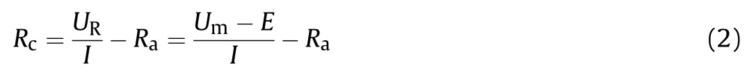
In actual experiments,the armature resistance is much smaller than the contact resistance and can be ignored without loss of accuracy. Therefore,the contact resistance can be expressed as:

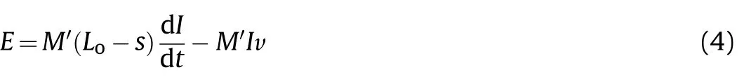
The muzzle voltage Umand the rail current I can be obtained by measuring, and E can be calculated by the following formula. The induced voltage E can be expressed as the following equation[13]:
2.2. Dynamical equation
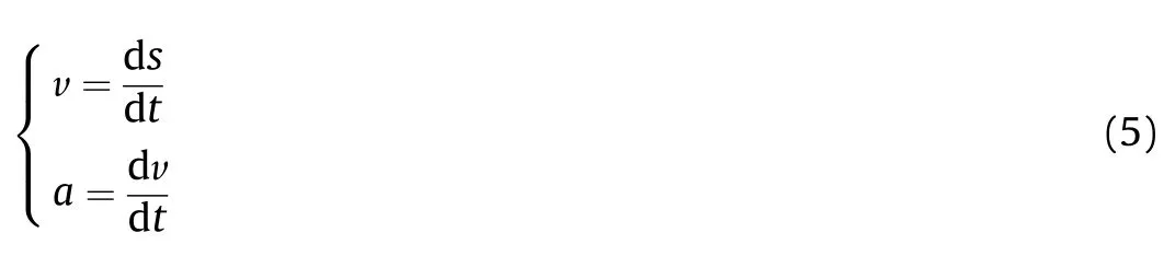
According to measured displacement s of the armature, the velocity v and the acceleration a can be calculated by the following formula:
The armature in motion is affected by electromagnetic thrust Fp,frictional resistance fcand air friction fair.According to the Newton’s law, the frictional resistance on one side can be express as:
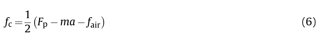
The electromagnetic thrust and the air resistance in (6) can be obtained by:

where CDis the coefficient of windward resistance, ρairis the air density and Awis the windward area.
2.3. Calculation equation of friction coefficient between armature and rails
When the electromagnetic propulsion force is greater than the maximum static friction, the armature starts to move. The friction coefficient between the armature and rails can be expressed as:
where Fcis the contact stress of the armature-rail contact surface.It consists of two units: the electromagnetic pressing force FEMand the mechanical stress Fmebased on interference fit. Therefore, the contact stress can be expressed by the following equation:

where A is the contact area and plis the mechanical stress.
The electromagnetic pressing force is proportional to the electromagnetic thrust and can be expressed as the following equation:

where γ is the coefficient of electromagnetic force.
Under the assumption of elastic deformation, the mechanical stress plcan be derived from Hooke’s law [18]:

where Eaand Erare the elastic modulus of armature and rails respectively, w is the inner rail thickness, D is the railgun caliber,and c is the interference of armature.
If the thermal strain is ignored, the armature interference is reduced due to melt wear, and can be obtained by the following equation [18]:
Fig.1. Two-dimensional structure diagram of the augmented railgun.
where c0is the initial interference of the armature, and W is the thickness of the armature ablation wear per unit time.
Based on the principle of heat conduction, the calculation equation of the average wear rate under Joule heat and friction heat can be expressed as [19,20]:

where i is the rail current, fcis the friction between the armature and rail,v is the armature velocity,lais the contact length,ρais the armature density,is the armature specific heat, ρris the rail density,is the rail specific heat,is the armature melting point, T0is the initial temperature, kris the rail thermal conductivity, and ΔH is the phase change latent heat of the armature.
2.4. Three-dimensional finite element model
The finite element method can be used to calculate the mutual inductance gradient M′and the electromagnetic force on the armature. The laminated barrel in the experiment has very little effect on the muzzle voltage. Therefore, in order to reduce the amount of calculation, the influence of the barrel on the muzzle voltage is neglected in the simulation. Referring to launcher structure and launch parameters in the experiment, the threedimensional finite element model shown in Fig. 2 is established.Fig.2(a)is the three-dimensional model of the railgun,and Fig.2(b)shows the local mesh generation of the model.
3. Launching parameters and experimental results
3.1. Launching parameters
The armature is made of 7075 aluminum alloy,and the material of the rails is high-conductivity copper alloy. The launching parameters are shown in Table 1.
3.2. Experimental results
In order to calculate the contact resistance and friction coefficient, it is usually necessary to measure the physical quantities including armature displacement,muzzle voltage,and rail current.The signal acquisition system is shown in Fig. 3. The armature displacement is measured by B-dot probes. The muzzle voltage is measured by a Tektronix high-voltage probe with an attenuation ratio of 1:1000.The rail current is measured using a Rogowski coil.
The muzzle voltage and rail current measured in the experiment are shown in Fig. 4. And the armature displacement and velocity curves are shown in Fig. 5.
4. Calculation results and analysis
4.1. The simulation results of muzzle induced voltage
The input current in the 3D simulation model is the current shown in Fig.4.The mutual inductance gradient M′of the inner and outer rails is calculated by the finite element method, and the muzzle induced voltage is calculated by formula 4. The induced voltage consists of two parts: the induced electromotive force and the motional electromotive force.
4.2. The analysis of contact characteristics
According to the measurement results of Figs. 4 and 5 and the simulation results of Fig. 6, the contact resistance between the armature and the rail is calculated by (3). The curve of the calculated contact resistance with time is shown in Fig. 7.
To calculate the friction coefficient between the armature and rails, we developed a relevant calculation program in the environment of MATLAB according to the equations for calculating the friction coefficient in section 2.2 and section 2.3.The coefficient of friction under the interference fit condition calculated by this program is shown in Fig. 8.
According to the waveform features of the contact resistance in Fig. 7 and the friction coefficient in Fig. 8, the contact state can be divided into four characteristic phases:
Phase I is from 0 to 0.32 ms,which is the stationary phase of the armature.In this phase,the electromagnetic thrust is less than the maximum static friction and the dynamic friction coefficient is 0.The contact resistance decreased rapidly.Since the contact stress is only provided by the initial preload at the initial moment, the contact resistance is high. The rapidly rising current, on the one hand, increases the electromagnetic force, and on the other hand,causes a large amount of joule heat to accumulate on the contact surface, resulting in melting of the armature contact surface. The combination of the two leads to a rapid drop in contact resistance[21,22].

Fig. 2. Three-dimensional finite element model of the augmented electromagnetic railgun.
Table 1 Launching parameters.
Fig. 3. Schematic profile of the signal acquisition system.
Fig. 4. The curves of muzzle voltage and rail current.
Fig. 5. Armature displacement and velocity curves.
Phase II is from of 0.32 ms-0.75 ms,which is the startup phase of the armature.In this phase,the contact resistance still maintains a rapid downward trend, and the friction coefficient rapidly drops from 0.3 to 0.2. The armature velocity is very low and the current continues to increase. Due to the accumulation of Joule heat, the armature contact surface gradually melts. The contact resistance decreases with the increase of contact stress and the formation of aluminum melt film. There are two reasons for the reduction of friction coefficient: 1) the maximum static friction force is greater than the sliding friction force at the armature startup phase;2)the aluminum melt film plays a role of lubrication [23].
Due to the accumulation of joule heat, the armature contact surface gradually forms an aluminum melt film.
Phase III is from 0.75 ms to 2.7 ms, which is the contact resistance slow changing phase. The contact resistance reveals a fluctuating upward trend in the phase. Due to the contact resistance joule heat and friction heat,the armature is ablated and worn,and then the aluminum melt film is formed gradually on the contact surface.The aluminum melt film provides lubrication for the sliding electrical contact between the armature and the rails, and plays a positive role in reducing the friction coefficient of the contact surface [23,24]. However, the ablation and wear of the armature wall and the rising temperatures make the contact surface rougher and increase the coefficient of friction.In the phase of 0.75 ms-1.67 ms,the aluminum melt film plays a leading role,and the sliding friction coefficient gradually decreases to 0.15. In the phase of 1.67 ms-2.7 ms, due to the high speed and high current, the ablation and wear of the armature become more and more serious,and the friction coefficient starts to increase gradually.The contact resistance is affected by several factors: the aluminum melt film reduces the contact resistance; the increased temperature and reduced contact stress increase the contact resistance.The complex interaction of these factors leads to a fluctuating increase of contact resistance.

Fig. 6. Simulation curves of the muzzle induced voltage.
Fig. 7. Contact resistance curve.
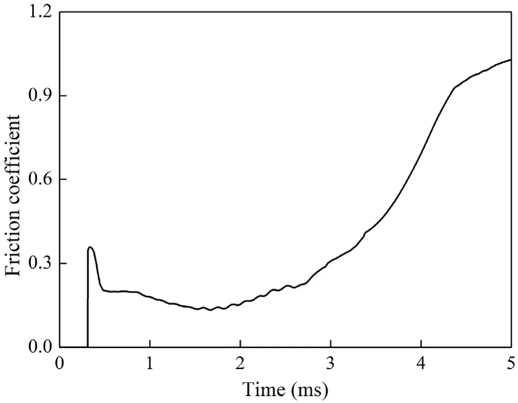
Fig. 8. Calculated friction coefficient curve.
Phase Ⅳis from 2.7 ms to 5 ms, which is the transition phase.The experimental value of the contact resistance sharply rises. At the beginning of the transition phase,the rapid decrease of current causes eddy current effect. This causes the instability of the aluminum melt film, and even the molten aluminum is ‘sprayed’out from the tail of the armature. Due to abrasion and ablation of the armature surface,the thickness of the wing-tail of the armature is reduced, which results in the consumption of the interference.Thereafter,as the current continues to decrease and the loss of the interference occurs, the contact force between the armature and rails drops sharply. With the decrease of the current and the decrease of the friction,the amount of heat generated is insufficient to maintain the aluminum melt film. The above reasons lead to an increase in contact resistance.In this phase, the calculated friction coefficient also shows a rising trend. One of the reasons is the deterioration of contact state caused by the loss of aluminum melt film.Another reason is that the instability of the pivotal rail contact creates an arc, which causes the armature current to be less than the rail current.
The friction coefficient calculated from the input current is greater than the actual friction coefficient. Therefore, a higher coefficient of friction indicates a decrease in contact reliability after transition.
4.3. Validation of contact characteristic analysis by rail pictures
The rail pictures of each phase after launch are selected and the above analyses of the contact characteristics can be verified on the base of the ablation and aluminum deposition of the contact surface.
Fig.9(a)shows the loading position of the armature:the heavily worn rail surface with less aluminum deposition leads to large contact resistance and friction coefficient during the start-up phase; Fig. 9(b) shows the resistance slow changing phase: more aluminum deposition on the contact surface indicates that a significant aluminum melt film is produced,so the contact resistance is small at this stage;Fig.9(c)shows the beginning of the transition:the aluminum deposition begins to decrease accompanied by ablation and the contact state begins to deteriorate;Fig.9(d)shows the later stage of transition phase: the amount of aluminum deposition on the contact surface is small and declining,indicating that the armature-rail contact state is unstable at this time.It can be seen that the contact characteristics analyzed by rail pictures are basically consistent with those analyzed by contact resistance and friction coefficient.
5. Conclusion
Due to the limitation of the contact resistance analysis method in the study of the contact characteristics of the augmented railgun,a combination analysis method based on the contact resistance and friction coefficient is proposed. In this paper, a quantitative characterization method of contact resistance and friction coefficient between armature and rails is established, and the contact resistance and friction coefficient in the experiment are quantitatively calculated. By comparing and analyzing the waveforms of the contact resistance curve and the friction coefficient curve, the contact characteristics are divided into four characteristic stages:the stationary phase,the startup phase,the contact resistance slow changing phase and the transition phase. The contact characteristics obtained by this method is more detailed and comprehensive.
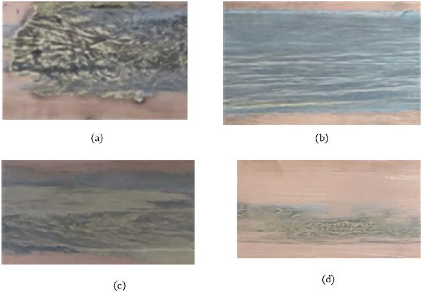
Fig. 9. Rail pictures of each stage.
Through the mechanism analysis of the sliding electrical contact process between the armature and the rails, the following conclusions can be drawn:
1) Under the combined action of contact resistance joule heat and friction heat, the armature is ablated and worn, and the aluminum melt film is gradually formed.
2) The aluminum melt film acts as a lubricant to reduce the contact resistance and the friction coefficient of the contact surface between the armature and rails.
3) The ablation and wear on the armature wall makes the contact surface rougher and increases the contact resistance and the friction coefficient.
4) The transition occurs when the input current drops rapidly,resulting in an increase in contact resistance and friction coefficient.Due to the ablation and wear of the contact surface,the interference is consumed and the contact state is significantly deteriorated.The above reasons cause unstable contact between the armature and the rails.
Declaration of competing interest
We declare that we do not have any commercial or associative interest that represents a conflict of interest in connection with the work submitted.
- Defence Technology的其它文章
- Aerodynamics analysis of a hypersonic electromagnetic gun launched projectile
- Synergistic effect of hybrid Himalayan Nettle/Bauhinia-vahlii fibers on physico-mechanical and sliding wear properties of epoxy composites
- Study on dynamic response of multi-degree-of-freedom explosion vessel system under impact load
- An investigation on anti-impact and penetration performance of basalt fiber composites with different weave and lay-up modes
- Modeling and simulation of muzzle flow field of railgun with metal vapor and arc
- Path planning for moving target tracking by fixed-wing UAV