
Study on dynamic response of multi-degree-of-freedom explosion vessel system under impact load
2020-07-02 03:16YunhoHuWeninGuJinqingLiuJinglinXuXinLiuYngmingHnZhenxiongWng
Defence Technology 2020年4期
Yun-ho Hu , Wen-in Gu ,*, Jin-qing Liu , Jing-lin Xu , Xin Liu , Yng-ming Hn ,c,Zhen-xiong Wng
a College of Field Engineering, Army Engineering University of PLA, Nanjing 210007, China
b Unit No.78102 of PLA, Chengdu 610031, China
c Unit No.31696 of PLA, Jinzhou 121017, China
d Research Institute of Chemical Defense, Beijing 102205, China
Keywords:Explosion vessel Dynamic response Vibration analysis Dynamic coefficient Load feature
ABSTRACT In order to study the dynamic response and calculate the axial dynamic coefficient of the monolayer cylindrical explosion vessel, the wall of vessel is simplified as a multi-degree-of-freedom (MDoF) undamped elastic foundation beam. Decoupling the coupled motion equation and using Duhamel's integrals, the solutions in generalized coordinates of the equations under exponentially decaying loads,square wave loads and triangular wave loads are calculated. These solutions are consistent in form with the solutions of single-degree-of-freedom(SDoF)undamped forced vibration simplified model.Based on the model,equivalent MDoF design method(also called MDoF dynamic coefficient method)of cylindrical explosion vessel is proposed. The traditional method can only predict the dynamic coefficient of torus portion around the explosion center, but this method can predict that of the vessel wall at any axial n dividing point position. It is verified that the prediction accuracy of this model is greatly improved compared with the SDoF model by comparing the results of this model with SDoF model and numerical simulation in different working conditions. However, the prediction accuracy decreases as the scaled distance decreases and approaches the end of the vessel,which is related to the accuracy of the empirical formula of the implosion load, the simplification of the explosion load direction, the boundary conditions, and the loading time difference.
1. Introduction
The explosive vessel can limit the sphere of action of explosive products and shock waves, which has extensive using value in scientific research,military affairs,explosive working,public safety and other fields.Its dynamic analysis can help researchers to design the explosion vessel and test the safety of it, which has important research value. W. E. Baker et al. (1960-1966) [1-3] laid a foundation for dynamic response analysis of explosive vessel. They simplified the vibration of the thin spherical shell into a single degree of freedom (SDoF) elastic vibration equation. Using the model, they obtained the analytical solution under the action of linear attenuation explosive loading and the elastic-plastic analytical solution of the vibration of the spherical shell under similar working conditions. Beyond that, they put forward the eccentric explosion theory.On these basis,A.F.Demchuk(1968)[4]simplified the explosive vessel into spherical symmetric or cylindrical symmetric structure, and obtained the formula about the maximum impulse and the maximum stress of shell through dimensionless analysis, which is called Baker-Demchuk stress criterion.Based on this criterion,The equivalent SDoF design method for explosive vessels was first described by Demchuk[4].In China,S. D. Zhao (1989) [5] first systematically introduced this design method adopted by the former Soviet union, which is also called dynamic coefficient method.U.A.Konon et al.(1987)[6]obtained the dynamic load on the wall of the explosion vessel by making the spherical charge equivalent to the actual charge, which has good practicability and reliability. A task group on impulsively loaded vessels was established by ASME,and the rules for the construction of explosion vessels was proposed in 1997[7].Q.Dong et al.(2011)[8]studied the mechanism of strain growth on the basis of previous studies, and put forward the design criteria of reusable explosion vessels considering strain growth.
The equivalent SDoF design method is widely used in the design and manufacture of explosion vessel in domestic,which requires to figure out the dynamic coefficient Cd,The product of Cdand peak of explosive loading P0is regarded as equivalent static pressure Pe.Then the wall of vessel, end cover, flange and bolt is designed according to GB150 “steel pressure vessel”. In addition, for safety purpose,the calculation of wall thickness needs to be multiplied by the safety factor to obtain the design wall thickness with certain redundancy.This SDoF design method,introduced by academician Zhao, essentially simplifies the radial forced vibration of the explosion vessel into a one-dimensional elastic motion of a mass block. Obviously, this method is quite suitable for spherical vessel but not for cylindrical explosive vessels.Because the axial pressure load on the inner wall along the axial direction is not uniform,which makes the wall vibration more complicated. Thus the traditional method can estimate the dynamical coefficient of the cylindrical vessel's implosion torus (torus portion around the explosion center)properly,but not the rest of the vessel wall,whose amplitude is smaller than that of the implosion torus. In order to solve the problem, this article simplifies the vessel wall for the internal force of MDoF beam on elastic foundation by the method of structural dynamics, estimates the peak displacement of forced vibration of the wall at different position without the interest of strain growth, and proposes the equivalent MDoF design method(also called MDoF dynamic coefficient method), also verifies the advantage of the new method by means of numerical simulation.
In addition,in recent years,there have been many studies on the strain growth of explosion vessels,but studies have shown that[9]the disturbance factors (structural perturbation, resonance caused by explosive loads, etc.) have not yet affected the response when the impulsive load has just reached the wall surface of the vessel.So this paper only discusses the container response in the first half period without strain growth.
2. Simplification of explosion vessel wall
Since the cylindrical explosion vessel is very similar to the cylindrical liquid storage tank,the analytical method of liquid storage tank can be used for reference to study the explosion vessel. F. Y.Huang et al. (1998)[10] derived a finite element method based on the beam theory on elastic foundation using line element, and solved the pressure vessel problem with uniform thickness for the first time.In addition,C.X.Zhang et al.(2007)[11]put forward the concentrated load method based on the theory of elastic foundation beam, and analyzed the deformation and internal force of reinforced concrete tanks,oil tanks and other cylindrical containers under compression. J. D. Wang et al. (2012) [12] proposed a semianalytical method. Using this method, the complex liquid storage cylindrical container is divided into several simple rigid annular baffles. The natural frequency and vibration mode of a plurality of rigid annular baffles with the same inner radius are analyzed, and the natural frequency and mode of the structure as a whole are obtained by the superposition principle.Spyros A.Karamanos et al.(2016) [13] studied the coupled response of horizontal-cylindrical elastic liquid containers under external seismic excitation under inviscid incompressible fluid and irrotational-flow conditions, and the model was tested using a half-full solution as an example.
As shown in Fig.1(a), the cylindrical explosion vessel generally consists of cylindrical vessel wall, ellipsoid/spherical end cover,flange, bolt and other parts. If the structure of flange and bolt is simplified as a fixed joint,and the influence of its mass on the vessel body is not taken into account,the explosion vessel can be regarded as the consolidation combination of the vessel wall and the two end covers, as shown in Fig. 1(b). The consolidation of container and ground is not considered. In addition, when the vessel wall is subjected to radial load,the axial displacement at the corner of the vessel wall and the end cover is very small, and the radial displacement at the corner is also very small due to the constraint of the end cover.Therefore,the radial and axial displacements can be ignored,and only the rotation of the vessel wall at the corner can be considered.Based on the above analysis,the corner under stress can be regarded as a hinge connection, so the vessel wall can be further simplified into the cylindrical shell structure with two hinged ends as shown in Fig. 1(c). The complex membrane and bending force (including transversal shear, bending moment and torque) of the cylindrical shell is simplified, and the shell is simplified to a single beam with two hinges ends and shown in Fig.1(d). In this beam, only two dynamic only two dynamic characteristics were considered, the first is radial displacement(deflection) and the second is bending moment and shear force caused by rotation.
Damping has little influence on the natural frequency of the system in practical engineering [14]. Therefore,ignoring the influence of damping force and using the equivalent mass method,beam can be simplified into several masses constrained by springs[15]. mi(i=1,2, …,n) is 1/(n+1) of the total mass, shown in Fig. 2,and the remaining mass is supported by the hinge points at both ends.Under this assumption,the mass can only move radially,and the flexural rigidity is EI (E is young modulus, I is the moment of inertia of the section to the neutral axis). Next, through the structural mechanics analysis,the motion equation of the system can be established by using stiffness method or flexibility method.And the flexibility matrix Δ can be calculated by function expression of deflection, which is derived from the elastic foundation beam model.The footnote is that this system is a non-rigid body motion system (this system is positively definite). Therefore, the stiffness matrix is a nonsingular matrix and is inverse matrix with the flexibility matrix [16].
3. Free vibration of system
Solving the displacement response of the forced vibration of the system under explosive loading requires the natural frequencies ωjand vibration mode φj(j=1, 2, …, n) in the state of free vibration.Then the solution in the generalized coordinate is obtained by substituting them into the motion equation under forced vibration.
The equation of motion for free vibration of an undamped system is

Where M is the mass matrix, K is the stiffness matrix, Y is the acceleration vector, Y is the displacement vector.
3.1. The natural frequencies and mode
The natural frequencies and mode can be solved by the following equation

Where

Since stiffness matrix and the flexibility matrix are inverse matrices, Eq. (2) can be written as follow

Fig.1. Model of cylindrical explosion vessel and its simplification.
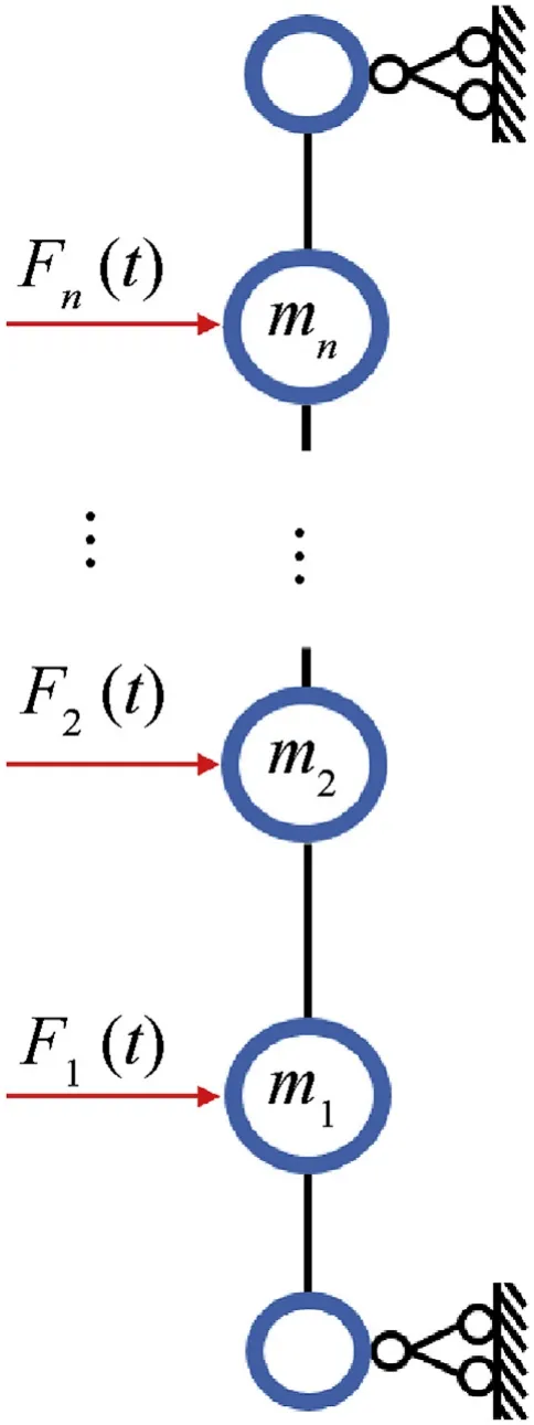
Fig. 2. MDoF system of beam.

Where

According to Eq. (4), the n-order natural frequency and the corresponding mode can be obtained by using the classical matrix iteration method [16]. The calculation method of flexibility matrix Δ will be described in the following.
3.2. Calculation of flexibility matrix
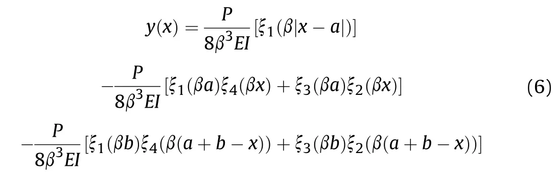
The elastic foundation beam method has been widely used in the analysis and research of various models, including thermomechanical bending response of FGM thick plates, free vibration analysis of nanoscale plates, buckling analysis of a single-walled carbon nanotube embedded, etc [17-19]. As early as 1992, M.Chiba [20] considered the bottom of a liquid-filled cylindrical container as an elastic foundation support, and analyzed its linear free axisymmetric vibration.The model of this paper considers the shell as a finite length elastic foundation beam hinged at both ends,shown in Fig. 3. Therefore, its displacement expression under the concentrated load can be expressed as [10,11]:
Where

ν is the Poisson ratio of material,R is the radius of cylindrical vessel wall,δ is the half of wall thickness.
The element δijof the flexibility matrix Δ indicates that a unit force applied in the j-th degree of freedom direction, causing the displacement of the i-th degree of freedom. Therefore, by substituting the values of a and b of the j-th mass subjected to unit force into Eq. (6), the deflection of each degree of freedom in the axial direction can be calculated, that is, the j-th column of the flexibility matrix is obtained.
3.3. Calculation of inertia moment
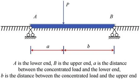
Fig. 3. Finite length elastic foundation beam with two hinged ends.
The flexibility coefficient is related to the inertia moment I of the section to the neutral axis. In fact, the neutral plane of the cylindrical section(Fig.4)subjected to internal force is not a plane but a cylindrical surface. Therefore, using cylindrical coordinates is simpler when calculating I.Rois the outer radius of the vessel wall,Riis the inner radius of the vessel wall, the position ρ= Rcis the neutral axis of the section. Then
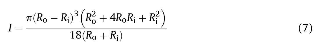
In fact, the ring section can be expanded into a rectangular to approximate calculate

Where D is the diameter of the vessel, 2δ is the thickness of the vessel.
4. Dynamic response under impact loading
4.1. The motion equation of MDoF system
When the explosive loading reaches the center of the beam(i.e.the implosion torus of the explosion vessel), it is 0, while t1is the positive pressure action time of explosive loading. In a smaller explosion vessel, there is a small difference between the starting and ending time of the load at different positions,so the function of the load on different masses is simplified to the product of the amplitude factor fi(i=1, 2, …, n) and the characteristic load function. Among them, the waveform of characteristic load can be exponential decaying wave, square wave, triangular wave, etc., as shown in Fig. 5. The reflected overpressure of every mass can be calculated according to Henrych's formula and the formula of reflected overpressure.Then the pressure of the explosive torus is set to unit 1, which is normalized with the pressure to obtain the amplitude factor vector f.
The explosion load response of the MDoF system is divided into two phases. Firstly, when 0 ≤t ≤t1, the beam is forced to move under the action of load;Secondly,when t >t1,the system is free to vibrate after the external load is unloaded. In engineering, the analysis of the maximum displacement of the beam under load(which is the basis for obtaining the dynamic coefficient Cd) is the focus of attention. Therefore, the case of t >t1will not be considered if the maximum displacement point has been reached in the time range of 0 ≤t ≤t1.
Under the action of arbitrary explosive load F(t), the motion equation of a system is [16].

This is a coupled equation of motion. For ease of solution,decouple it by using generalized coordinates, and it can be obtain that

Where, generalized mass, generalized stiffness and generalized load are respectively
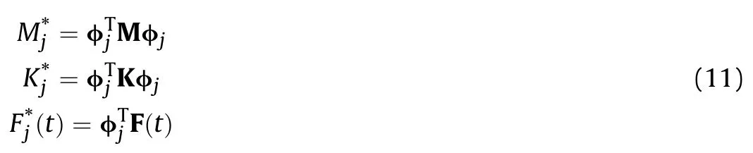

Where φjis the j-th mode. And This equation relates the generalized mass to the generalized
stiffness by the natural frequency ωj[16].
4.2. Generalized coordinate solution of dynamic response under impact load
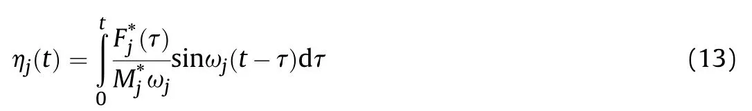
In the time range of 0 ≤t ≤t1,when the load acts directly on the beam,the solution of the generalized coordinates can be given by Duhamel integral[21]. It is
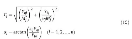
For t >t1, when there is no longer a load on the beam, the solution can be derived from the initial value problem of free vibration. The general solution form of free vibration is as follows:

Where the parameters Cjand αjare determined by the initial conditions. These two parameters can be further determined by using the orthogonality of the vibration modes of the MDoF system[21]. When t = 0, the parameter is Y(0) = Y0, ˙Y(0) = ˙Y0, andThe solution has a parameter of

Fig. 4. Cylindrical section subjected to internal forces.

Fig. 5. Three waveform loads.
In the actual engineering design of the explosion vessel, a simplified pressure waveform is generally used, and for the dynamic response in the elastic range of the container shell, the maximum displacement generated by the exponentially decaying simplified load is closest to that generated by the actual simulated load, so an exponential function can be used to simulate the reflected overpressure waveform generated by the blast [22].
For MDoF systems, the exponentially decaying load is

In the formula: SF= 2πRil/(n + 1), SFis the loading area of a single mass,P0is the peak value of the load of implosion torus.F0is the equivalent pressure applied to the implosion torus (the intermediate mass of the beam), α is the decay coefficient. Using Duhamel's integral, generalized coordinates of the j-th order frequency can be obtained as follow:

By using the method of element changing, let t -τ = u and then the integral result can be obtained:

The study by U.A.Konon et al.(1987)[6]shows for the first time that the addition of a foamed aluminum sandwich layer in a singlelayer explosion vessel can greatly improve the antiknock performance. The sandwich layer of the explosion vessel causes a significant slowing of the rising and falling edges of the load acting on the wall,resulting in a wider pulse[23-26].So this kind of load can be reduced to a square wave.In addition,the load is often simplified to a triangular wave in the engineering[27,28].Since the derivation of the solution of the vessel wall response under these two loads is similar to the above,this paper only lists the results of the solution under generalized coordinates,as shown in Table 1.
Comparing the SDoF model derived by predecessors,the two are similar in form[5].The solution of the MDoF model in generalized coordinates is different from the SDoF solution in that the inner product of the mode vector φjand the amplitude factor vector f is added to the numerator. It shows that the vibration response modes of each frequency in the generalized coordinates are the same,and they all vibrate in a basic waveform of SDoF.The overall vibration of the system is a linear superposition of the fluctuations of various frequencies. It should be noted that, in addition to the rectangular pulse and triangular pulse discussed in literature [5]and in this paper,the shock wave is simplified as a parabolic shock wave in literature[5],while this paper believes that the application of simplifying the shock wave as an exponential decay wave is widely applied. Therefore, the loading waveform of exponential decay wave is deduced instead of a parabola type wave.
4.3. Displacement response vector
The MDoF system is a linear system,so the displacement vector Y can be decomposed into a linear combination of the modes byusing the orthogonality, that is,

Table 1 Generalized coordinate solution under different impact loads.

Table 2 Material parameters of steel.
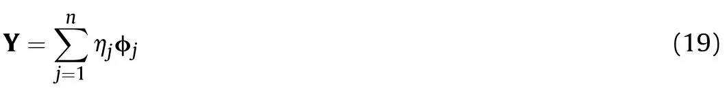
Substituting this equation into the motion Eq.(9)coupled MDoF system, and then using the orthogonality of the mode, the decoupled motion Eq.(10)can be obtained.Therefore,the solution of the MDoF problem can be solved by simply bringing the solution of the generalized coordinates back to the above equation.
5. The example and numerical simulation
Example: There is a cylindrical explosion vessel with an inner radius Riof 40 cm and a wall thickness 2δ of 2.2 cm. Its height L is 110 cm.The material is 16MnR steel,and the parameters are shown in Table 2.Use the equivalent SDoF model,MDoF beam model and numerical simulation to analyze the vibration response of the wall under the pressure of 150 g TNT at the center of the vessel.
The solution process is as follows:
5.1. Equivalent SDoF model
Step 1: Calculation of the reflected pressure.Scaled distance:
Where r is the charge distance,equal to the inner radius Riof 40 cm 0.3 <<1, Thus calculate incident overpressure using the Henrych formula

Reflected overpressure:

Where incident angle φ0is 0, p0is 1 atm.
Step 2: Calculation of positive pressure time.

Where η is the empirical coefficient,0.5 is taken when it is cylindrical symmetry, and 0.35 is taken when it is spherical symmetry;Q0is detonation heat, 4.2297×10⁶J/kg is taken when it is TNT.
Step3: Calculation of the fundamental frequency and stiffness
Step4: Calculation of the forced vibration displacement. In the equivalent SDoF model, the mass displacement equation under three waveform loads is given[5],as shown in Table 3.Where F0is the product of the force bearing area S of the inner surface and the peak pressure P0(P0= p0+ Δp2). Selecting the triangle wave as the load, the displacement-time curve is obtained by the expression, as shown in Fig. 7, the black dotted line.
5.2. MDoF beam model
First, the degree of freedom n is determined based on the accuracy of the study. It is found through calculation that the calculation accuracy of each order frequency increases as the value of the degree of freedom increases.For the fundamental frequency,when taking the 7th degree of freedom,the error between the value and the stable solution is only 3%. Therefore, this calculation takes the degree of freedom n=7.
The method of step1 and 2 are basically the same with the method of SDoF method, and it only needs to calculate the amplitude factor f according to the method described in the first paragraph of Section 4.Under the dose of 150 g TNT,it can be obtained that f=[ 0.175, 0.404, 0.767,1, 0.767, 0.404, 0.175 ]T.
Step3:According to the method described in Section 3,calculate the natural frequency ωjand the vibration mode φjin the state of free vibration, and the calculation results are shown in Table 4.Step4:According to the method described in Section 4,calculate the displacement under the generalized coordinates by selecting the triangular wave and the exponentially decay wave load.Step 5: Substitute the generalized coordinate solution and the mode vector into Eq.(19),and re-synthesize the solution in the line coordinates. As shown in Fig. 7, the red line, from top to bottom, is the forced vibration displacement curve of the implosion torus, 3/8 point, quarter, and eighth point respectively.The MDoF beam is symmetrical in the calculation,so the displacement curves at 1/8 and 7/8 positions, 1/4 and 3/4 positions, 3/8 and 5/8 positions are coincident.

Table 3 Forced vibration displacement of equivalent SDoF model.
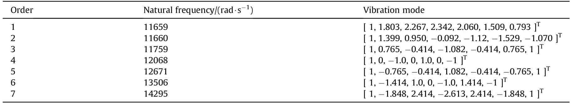
Table 4 Natural frequency and vibration mode calculation results.
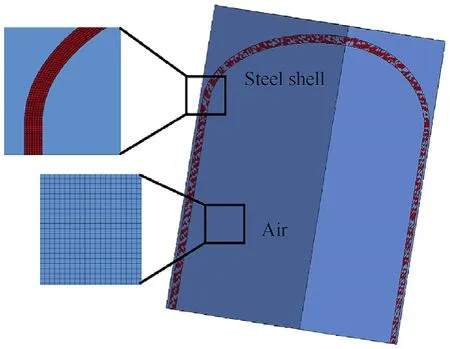
Fig. 6. Numerical model of explosion vessel.
Fig. 7. Displacement curve of forced vibration.
5.3. Numerical simulation
Numerical simulation with the method of fluid-solid coupling was carried out by using the commercial software LS-DYNA.The 1/8 model is built as shown in Fig.6.The material model of explosion vessel is the plastic-type kinematic hardening model(*MAT_PLASTIC_KINEMATIC), which material parameters are shown in Table 2. In addition, Cowper and Symonds model is adopted in plastic-type kinematic hardening model to represent the scaling of yield stress by the change of strain rate,as shown in the following formula
In this paper,the coefficients C and P related to strain rate is set as 105and 5, respectively. In addition to the plastic deformation part, the model also includes the elastic deformation part during the early deformation of the material. The empty shell model(*MAT_NULL)is adopt for the air,which considers the air viscosity and is suitable for use with the ideal gas state equation.The initial density of air is set to 1.29×10⁻³g/cm3,the polytropic exponent γ is 1.4,and the initial pressure is 1atm.The initial energy density is set to 2.50 MPa. The model of explosive is the high-energy combustion model (*MAT_HIGH_EXPLOSIVE_BURN) and is used in conjunction with the common JWL state equation. Explosive parameters and JWL equation parameters are shown in Table 5 and Table 6.
The 7 octant points of the vessel wall are taken as the observation point. Their displacement-time history curve is shown in Fig. 7. The blue lines, which is from the top to the bottom, are the forced displacement of points at implosion torus,3/8 point,quarter,and eighth point. The response of the tank is within the elastic strain of the material due to the small charge.
It can be seen from the comparison of the three sets of curves that the traditional equivalent SDoF model has a small description of the forced vibration displacement of the implosion torus. The numerical simulation result of the maximum displacement of the implosion torus is 0.239 mm, while the maximum displacement calculated by the traditional model is only 0.152 mm, which is a deviation of 36.4%compared with the numerical simulation.It can be seen that the calculated dynamic coefficient will be too small.However, the MDoF model proposed in this paper has a better consistency with the numerical simulation in predicting forced vibration. The maximum displacement of the implosion toruscalculated by the model is 0.261 mm, which is only 9.2% larger. In this way, a more accurate dynamic coefficient can be obtained by calculating the ratio of the maximum displacement under explosive loads to the maximum displacement of the vessel wall under static pressure. Moreover, this method is better than the SDoF design method, which can obtain not only a better dynamic coefficient of the implosion torus, but also the dynamic coefficient of any n-point position in the axial direction of the vessel wall.

Table 5 Material parameters of TNT explosives.
Table 6 Parameters of JWL equation.
Table 7 Numerical simulation experiment under different working conditions.
6. Numerical simulation under various working conditions
In order to investigate the applicability of the equivalent MDoF design method under various working conditions, this paper uses the numerical simulation method in section 5.3 to design four sets of numerical simulation experiments, as shown in Table 7. In addition the results of SDoF and MDoF design method are compared with the simulation results.To meet the requirements of calculation accuracy, and considering the space is limited, the degree of freedom of 11 is adopt in this section, and only the maximum values of the forced vibration displacements of the implosion torus, three dividings point and six dividing points are compared in this section. The results are shown in Fig. 8.
6.1. Comparison and analysis

Fig.8. The maximum displacement of forced vibration at each point of vessel wall under different conditions of(a)Dose of TNT(b)Thickness of wall(c)Length of wall(d)Radius of vessel.
Table 8 The error of the SDoF model and the MDoF model compared with the numerical simulation results.
By comparing with the numerical simulation results, the MdoF model is fairly accurate for predicting the elastic response of the container vessel under the impact load.In particular,the implosion torus response at different wall thicknesses and the radial length of the container vessel, as shown in Fig. 8(b) and (c), the black solid dot-line, the prediction results of the MDoF model are basically coincident with the numerical simulation results. Observing Fig.8(a)and(d),it is found that when the dose is small,the MDoF model can better predict the response,and when the dose is large,the prediction results are biased. Similarly, in the case of a small vessel radius, the prediction results of the MDoF model are also unremarkable. This is because the empirical formula of the charge explosion is used in the calculation of the model to estimate the peak value of the impact load.When the scaled distance is too small(the dose is small or the blasting height is large), especially when the scaled distance is much smaller than 1,the empirical formula is more distorted for the prediction of the explosive load, which affects the accuracy of the model calculation.
The prediction results of the SDoF model are also given in Fig.8.Table 8 shows the error of the implosion torus response of the SDoF and the MDoF model compared with the numerical simulation results. It can be found that the SDoF model generally has more than 1/3 error than the simulation result. At the same time, the error of the MDoF model is much smaller than that of the SDoF model except for a few cases.
In addition,the red and blue dotted lines in Fig.8 are the radial displacement responses of the three dividing and six dividing points, respectively. Among them, the MDoF model has a small prediction error at the three dividing point, which is basically within 20%, which has a guiding significance for container vessel design. However, the model has a large prediction error at the six dividing point and only has a certain reference value.This is caused by the following three reasons. One is because the real explosion vessel wall is obliquely incident on the wall except that the implosion torus is normally incident by the blast wave.In order to simplify the model, the model only considers the pressure of the oblique incident wave,and simplifies the oblique incident impulse into the radial normal incident impulse, which makes the farther away from the implosion torus.The second reason is that the model simplifies the connection between the end of the vessel wall and the end cover as a hinge.Although it is closest to the actual working conditions, there are still some discrepancies. Finally, because of the effect of the actual implosion wavefront, there is a time difference in the axial direction, that is, the inner wall near the end cover is subjected to the impact later than the middle section.However,the MDoF model ignores the time difference,which leads to the ignoring of the effect of first excited middle section on the end.
In the further study, the model accuracy can be improved through the following three aspects: a) The empirical formula of implosion load can be improved, especially the formula with the scaled distance less than 1. b) The radial MDoF model can be improved into radial and axial MDoF model.c)The time difference of loading should be considered.
6.2. The influence of parameters on the maximum displacement
Further analysis of Fig.8 shows the effect of parameters such as dose,wall thickness,wall length and radius on the maximum radial displacement at different positions.
It can be seen from Fig.8(a)that the maximum displacement at the implosion torus or other n-points tends to increase linearly with the increase in the dose of charge. And the closer to the implosion torus, the greater the effect of the dose on the forced vibration displacement.As shown in Fig.8(b),as the wall thickness increases, the maximum displacement at each n-point is exponentially attenuating. It can be foreseen that the maximum forced vibration of each point approaching to zero when the wall thickness is infinite.Fig.8(c)shows that the maximum displacement of the implosion torus is hardly affected by the length of the vessel wall. And as the vessel elongates, the far-explosive end (near the vessel end) tends to move less. An interesting phenomenon is shown in Fig.8(d),that is,as the radius of the vessel increases,the maximum displacement value at each n-point becomes closer and closer.This is because as the propagation distance of the explosion wave increases, the wavefront radius becomes larger and larger,and its shape becomes closer to the plane. When the shock wave close to the plane acts on the wall of the vessel,the loading time of each n-point is basically the same, the pressure is similar everywhere, and then the response tends to be the same.
7. Conclusions
(a) In this paper, the explosion vessel wall is simplified into a MDoF undamped elastic foundation beam. The Duhamel integral is used to calculate the generalized coordinate solutions under exponentially decaying load,square wave load and triangular wave load.This result is similar in form to the solution of the simplified model of SDoF undamped forced vibration.
(b) In this paper, the equivalent MDoF design method of cylindrical explosion vessels (or MDoF dynamic coefficient method) is proposed by using the MDoF beam model. The steps to obtain the dynamic coefficient are as follows:Step 1,calculate the reflection pressure and amplitude factor.Step 2,calculate the positive pressure action time. Step 3, calculate the natural frequency and mode under free vibration.Step 4,select a simplified load model and calculate the generalized coordinate solution. Step 5, synthesize the solution in the linear coordinates. Step 6. Take the maximum value of the forced vibration of each observation point and divide it by the displacement of the vessel wall under static pressure to obtain the dynamic coefficient at different positions.
(c) For the prediction of forced vibration displacement of the implosion torus, the model has greatly improved the prediction accuracy compared with the equivalent SDoF model.In addition,the response of forced vibration at other n-points of the vessel wall can be well predicted. However, the prediction accuracy of the model decreases with the decrease of scaled distance and close to the wall end.In order to improve the accuracy,the model can be improved from the following three aspects:i)The empirical formula of implosion load can be improved. ii) Radial and axial MDoF model can be adopted. iii) The time difference of loading shall be considered.
Acknowledgments
This work was supported by grants from the Department of Infrastructure Barracks and National Science-Technology Support Plan (Grants No.BY209J033 and 2012BAK05B01).

- Defence Technology的其它文章
- Analysis of sliding electric contact characteristics in augmented railgun based on the combination of contact resistance and sliding friction coefficient
- Aerodynamics analysis of a hypersonic electromagnetic gun launched projectile
- Synergistic effect of hybrid Himalayan Nettle/Bauhinia-vahlii fibers on physico-mechanical and sliding wear properties of epoxy composites
- An investigation on anti-impact and penetration performance of basalt fiber composites with different weave and lay-up modes
- Modeling and simulation of muzzle flow field of railgun with metal vapor and arc
- Path planning for moving target tracking by fixed-wing UAV