
An investigation on anti-impact and penetration performance of basalt fiber composites with different weave and lay-up modes
2020-07-02 03:16HidongFuXinFengJinxuLiuZhimingYngChunHeShukuiLi
Defence Technology 2020年4期
Hi-dong Fu , Xin-y Feng , Jin-xu Liu ,b,*, Zhi-ming Yng , Chun He , Shu-kui Li
a School of Materials Science and Engineering, Beijing Institute of Technology, China
b China National Key Laboratory of Science and Technology on Materials under Shock and Impact, Beijing Institute of Technology, China
c State Key Laboratory of Explosion Science and Technology, Beijing Institute of Technology, China
Keywords:The woven basalt fiber composites The [0°/90°/45°/-45°]s basalt fiber composites Low velocity impact Ballistic test Delamination
ABSTRACT The woven basalt fiber composites (WBFC) and the unidirectional [0°/90°/45°/-45°]s basalt fiber composites (UBFC) were prepared by hot-pressing. Three-point bending test, low velocity impact test, and ballistic test were performed to the prepared composites. After the tests,the specimens were recovered and analyzed for micromorphology.Three-point bending tests show that both the bending strength and stiffness of the WBFC surpass those of the UBFC. Low velocity impact test results show that the low velocity impact resistance to hemispherical impactor of the UBFC is higher than that of the WBFC,but the low velocity impact resistance to sharp impactor of the UBFC is lower than that of the WBFC. For the ballistic test,it can be found that the ballistic property of the UBFC is higher than that of the WBFC.After the tests,microscopic analysis of the specimens was applied,and their failure mechanism was discussed.The main failure modes of the UBFC are delamination and fibers breakage under the above loading conditions while the main failure mode of the WBFC is fibers breakage. Although delamination damage can be found in the WBFC under the above loading conditions,the degree of delamination is far less than that of the UBFC.
1. Introduction
Basalt is a natural material that is found in volcanic rocks originated from frozen lava. Basalt fiber is made from basalt rocks,which are broken and put into the furnace melting approximately in the range of 1500-1700°C, then pulled into silk by platinumiridium alloy leaking plate [1]. Basalt fiber is natural, non-toxic,eco-friendly, inexpensive, and rich in source, normally known as the“twenty-first century nonpolluting green material”[2,3].Based on the above advantages,basalt fiber is widely used in many fields,such as pressure pipes, fibrous insulators for residential and industrial buildings, protective clothes, and fire blocking materials and so on.Basalt fiber has been also used in military fields since it was discovered in 1923 [2]. In armor protection field, compared with common bullet-proof fibers such as glass fiber, aramid fiber,ultra-high molecular weight polyethylene (UHMWPE) fiber, basalt fiber has excellent comprehensive performances. The chemical composition of basalt fiber,including SiO2,Al2O3,CaO,MgO,Fe2O3and FeO,is similar to glass fiber while basalt fiber is more stable in strong alkalis condition than glass fiber [1]. In the same way, the density of basalt fiber (2.63-2.8 g/cm3) is similar to E-glass(2.54-2.57 g/cm3)and S2-glass(2.54 g/cm3),but a little higher than carbon fiber (1.78 g/cm3) [3]. In addition, basalt fiber has higher tensile strength than E-glass fiber,greater failure strain than carbon fiber,as well as good resistance to chemical attack,fire and impact[4]. Additionally, basalt fiber has high cost performance compared with aramid fiber, carbon fiber and UHMWPE fiber. These advantages make basalt fiber a promising material in military protective fields[3,5].However,there are relatively little research done in the protection field. Especially, there are shortage of studies on the influence of the weave and lay-up modes on the mechanical properties and protective performance. Furthermore, the study on the anti-impact and penetration performance of basalt fiber composites are not systematic and in-depth under the influence of different loading methods and strain rates, which will be further explained below.
The various arrangement and assembly of fibers, and their orientations within the fabric lead to characteristic changes in mechanical properties as well as the way of destroying the materials[2]. Many scholars [6-9] have carried out researches on the mechanical properties of the composites with different weave and layup modes. Morioka [6] et al. studied the carbon fiber composites with four kinds of weave and lay-up modes, and found that the weave and lay-up mode had a significant influence on the mechanical properties.The mechanical properties of the[0°/90°/45°/-45°]scomposites were the same when loaded in different directions,and their bending strength was 30%-40%lower than that of the[0°]scomposites.Zhao et al.[7]found that the anisotropy of the glass fiber composites was obvious when the weave and lay-up mode was[0°]s,of which the tensile strength along the direction of the fibers was the highest, while the anisotropy of mechanical properties of the[0°/90°/45°/-45°]scomposites was not significant.Thus, the [0°/90°/45°/-45°]scomposites could be regarded as an approximate isotropic material. Previous studies are conducive to understand the effects of weave and lay-up modes on the mechanical properties of composites. However, these researches are mainly in the field of carbon fiber and glass fiber composites so that more research attentions should be paid to the mechanical properties of basalt fiber composites with different weave and lay-up modes.
The loading methods of the composites will be different in various applications, and the mechanical properties of the composites will be affected when the loading methods change. This means that loading at different impactors and at different strain rates affect the performance of the composites. When used in the protection field,the composites may encounter low velocity impact by sharp impactor such as daggers, bayonets and blunt impactor such as bricks and stones. Sometimes the composites may be impacted under high strain rate loading in the service environment,for instance impacted by bullets and fragments at high velocity.There are also many studies on the anti-impact and penetration performance of composites under different loading methods.
For the low velocity impact [10-17], the [0°/90°]sand the [0°/90°/45°/-45°]sglass fiber reinforced epoxy resin matrix composites were studied, and it showed that both of the two composites had similar energy absorption properties and damage resistance [10].The low velocity impact resistances of basalt fiber composites were investigated in Ref. [11]. The results showed that the [0°/90°]scomposites had the best low velocity impact resistance,followed by the woven composites, while the unidirectional [0°]scomposites had the poorest low velocity impact resistance.Besides,researchers also focus on the numerical and experimental investigation of fiber composites subject to low velocity impact [12,13]. The studies showed that the numerical tool had been found able to fit the experimental activity and offer a comprehensive description of the damage devolution.
As for the research on high velocity impact[18-22],the ballistic performance of the basalt fiber reinforced composites showed that the [0°/45°/90°]scomposites had better ballistic properties than the [0°/90°]scomposites [18]. For the ballistic investigation of hybrid Kevlar and basalt composite armors reinforced,there was no significant influence of stacking sequence on the front face damage patterns,but it was changed for back face damage patterns[19].The difference of the damage shape may due to the energy absorption mode of the matrix [20]. However, most of the studies are about Kevlar fiber, UHMWPE fiber, and carbon fiber, and there is rare study on basalt fiber composites with different weave and lay-up modes. Furthermore, the impact conditions of the previous researches did not consider the influence of the shape of the impactors which are various in the actual service environment.
Moreover, the compared research on mechanical behaviors of composites under different loading rate are also the focus of researchers.The strain rate had a great influence on the strength and critical failure strain of carbon fiber composites, and the effect of the properties is more significant as the strain rate increased [23].As for the basalt fiber composites,the mechanical properties of the basalt filament tows are rather sensitive to strain rate[24].Besides,the tensile strength of the basalt fiber composites increased when the strain rate increased from 19 to 133 s-1,and the tensile modulus and critical failure strain increased by 45.5%, 17.3%, and 12.9%,respectively [4]. Although there are many studies on the mechanical behavior of composites under different rate loading conditions,they are mostly based on one same weave and lay-up method.Therefore, the influence of the weave and lay-up modes on the mechanical properties of the composites under different strain rate conditions need to be further discussed.
Previous studies on the mechanical properties of the composites with different weave and lay-up modes are mainly in the field of glass fiber, Kevlar fiber, UHMWPE fiber, and carbon fiber. Some studies on basalt fiber composites didn't involve the weave and layup mode of [0°/90°/45°/-45°]swhich is an important weave and lay-up mode of composites due to their characteristics of approximate isotropy.Furthermore,the impact conditions of the previous researches did not consider the influence of the shape of the impactors which are various in the actual service environment, and the basalt fiber composites under high strain rate are rarely studied.Therefore, there is still a lot of systematic and in-depth research work worth doing.
Basalt fiber used as a reinforcement can make a variety of composites with excellent performance,and it has wide application in the field of armor protection of national defense military[25,26].It can be used for personal protection, such as body protection armor, equipment protection, such as fighter armor, warship armor,tank armor, and other weapons and equipment armor. The use of basalt fiber composites can promote the upgrading of military weapons and equipment, enhance the combat effectiveness of the military [2,3,5]. In the actual application process, the service conditions and performance requirements of the basalt fiber composites vary in different protection fields[27-30].For example,the composites used in personal protection field should resist the impact objects and be prevented from being perforated,meanwhile the back convex height and back damage area of the composites are required to be as small as possible. Nevertheless, the core of equipment protection is to consume the energy of the damage element as much as possible and prevent the damage element from perforating the armor. Thus, the back is allowed to have relatively large convex,and the composites can absorb more energy through the back convex,which is beneficial to improve the anti-impact and penetration performance.In order to meet the different application requirements of basalt fiber composites, it is necessary to investigate the impact resistance of composites under different loading methods since there is a lack of research on ballistic performance and impact test with different impactors.Especially the researches of basalt fiber composites are less studied in this field.
In this paper,we designed and prepared the woven basalt fiber composites(WBFC)and the unidirectional[0°/90°/45°/-45°]sbasalt fiber composites (UBFC) according to the previous study. At the same time, we investigated their mechanical behaviors under different loading conditions in order to study the influence of weave and lay-up modes on the anti-impact and penetration performance. Three-point bending test, low velocity impact test with hemispherical impactor and sharp impactor,and ballistic test were studied on the two kinds of composites. Then the failure mechanism was analyzed according to the characteristic of the microstructure of the recovered specimens.Besides,the influence rules of the weave and lay-up modes on the anti-impact and penetration performance under different loading conditions were analyzed.This work filled in the shortcomings of the research on the influence of the weave and lay-up modes of basalt fiber composites on the anti-impact and penetration performance. Meanwhile this study clarified the choice of the weave and lay-up modes of basalt fiber composites applied to the different protective environment such as low velocity impact, high velocity impact, blunt or sharp object impact. It provided important experimental basis for the application of basalt fiber in the protection field.
2. Materials and experiment
2.1. Materials preparation
Commercial basalt fabrics(diameter 13 μm,areal density 300 g/m2, Shanxi ECIC basalt development CO., LTD.) are used in this study. The resins used are CYD-128 epoxy resin with methyl tetrahydrophthalic anhydride as curing agent, and 2,4,6-tris (dimethylaminomethyl) phenol as accelerator. The two different weave and lay-up modes are displayed in Fig.1,which exhibits the WBFC and the UBFC, respectively.
The two kinds of composites are both prepared by hot-pressing.Firstly, the epoxy resin, curing agent, and accelerator are mixed uniformly, and then the fabrics are impregnated. Next, the fabrics are laminated and put into a mold.The last step is hot-pressing.The content of the curing agent(methyl tetrahydrophthalic anhydride)in the epoxy resin matrix is designed to be 41.2 wt%, and the content of the accelerator (2,4,6-tris(dimethylaminomethyl)phenol) is designed to be 0.55 wt%.In order to obtain qualified specimens,the optimized hot-pressing procedure is pressure of 5 MPa, three periods with pressing temperatures of 100°C,120°C,150°C, respectively, and the holding time of 1 h for each period. It is worth mentioning that the designed mold and optimized fabrication parameters realize the control of uniform compactness and fiber content of the composites.
2.2. Three-point bending test
The bending strength and deflection of the composites are investigated by three-point bending test according to GB/T11997-2008. Considering the influence of anisotropy in composites on the mechanical properties, the specimens are cut down from the two composites in three angles, as shown in Fig. 2. The specimens from the WBFC are named as specimen A, specimen B, and specimen C for clarification. Similarly, specimens from the UBFC are named as specimen A′, specimen B′, and specimen C′.
2.3. Low velocity impact test
The low velocity impact resistance of the composites is measured by CEAST-9350 drop tower impact system. The total weight of drop hammer is 15.47 kg, including counterweight of 10 kg,fixed counterweight of 4.3 kg,and impactor weight of 1.17 kg.According to ASTMD3763,the specimens are fixed by a pneumatic loop fixture whose internal diameter is 76 mm.The impact point is the center of the specimen, and the force-displacement curve can be recorded during impact.There are two impactors used in the low velocity impact tests, as shown in Fig. 3. The hemispherical impactor is the standard impactor of the low velocity impact equipment, and the sharp impactor is designed similar to the 12.7 mm armor-piercing projectile core for the purpose of comparing with the subsequent ballistic test.The tests are repeated at least 5 times for every specimen whose parameters are shown in Table 1.
2.4. Ballistic test
The ballistic test system consists of launching system, velocity measuring device, target fixing device and after-effect plate. The schematic of ballistic test set-up is shown as Fig. 4. The ballistic tests use depth-of-penetration(DOP)test techniques,and the 6061 aluminum plates are used as reference plate and after-effect plate,as shown in Fig. 5. The aluminum plate used as after-effect plate with a thickness of 30 mm is placed parallel to the target plate,and the spacing between the two plates is 10 mm. The target plate parameters of basalt fiber composites for ballistic impact test are shown in Table 2. The ballistic properties of the composites are characterized by the ballistic efficiency index-differential efficiency factor (DEF), which can be calculated by the following formula:
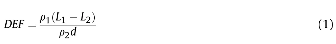
where,L1is the penetration depth of the reference plate;ρ1and L2are the density and residual penetration depth of the after-effect plate, respectively; ρ2and d represent the density and thickness of the composite plate (the target), respectively. The calculation method of DEF is shown as Fig.5.L1and L2can be obtained in the ballistic tests, and other parameters can be measured before the tests.
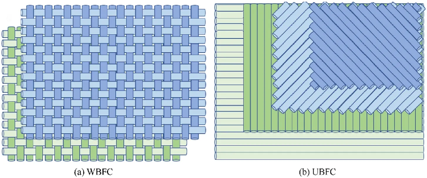
Fig.1. The schematics of weave and lay-up modes of composites: (a) the WBFC; (b) the UBFC.

Fig.2. Schematic of cutting directions of the specimens for three-point bending test:(a)the WBFC;(b)the UBFC;(c)three cutting directions;(d)schematic of specimen in threepoint bending test.
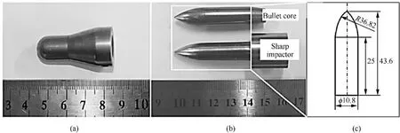
Fig. 3. Photograph of hemispherical impactor (a) and sharp impactor (b); (c) dimension figure of sharp impactor.
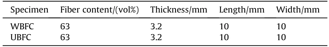
Table 1Specimen parameters of basalt fiber composites for low velocity impact test.
3. Result & discussion
3.1. Three-point bending property and failure mechanism
In order to compare the deformability resistance and bending strength of the two composites,three-point bending test is carried out.Fig.6 depicts the three-point bending stress-deflection curves of the WBFC specimens. There is a significant difference in the stress-deflection curves among specimen A, specimen C and specimen B.The fibers weave and arrangement of specimen A and specimen C are actually the same. Therefore, the stress-deflection curves are almost completely coincident with the maximum strength of 497 MPa and the maximum deflection of 5.9 mm. The bending strength of specimen B is the maximum of 265 MPa,but it has not fractured until the deflection reached 22.0 mm. It shows that the WBFC in the orientation of specimen B have the best plastic deformation ability under the bending loading, and the WBFC in the orientation of specimen A and C have the maximal deformation resistance.
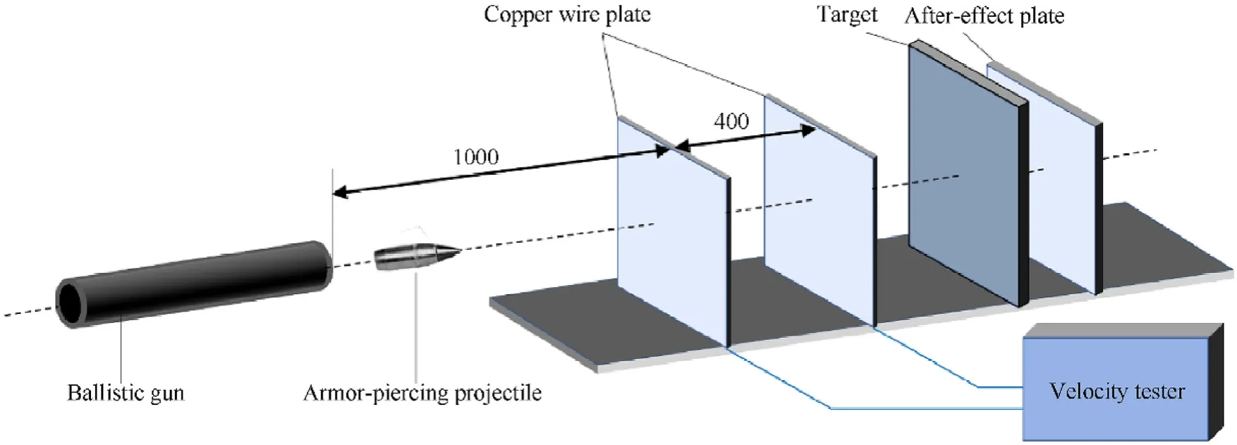
Fig. 4. Schematic of ballistic test set-up.

Table 2 Target plate parameters of basalt fiber composites for ballistic impact test.
For further analyzing the fracture mechanism, the specimens are observed after loading, and the microstructure of the destruction areas are enlarged in Fig. 7. Specimen A and Specimen C are shown in Fig.7 where there can be found obvious delamination and fracture. Under the vertical loading, the back of the specimen is subjected to tensile stress. Thus, the cracks initiate at the back surface of the specimen firstly and then expand vertical to the fabrics. At the same time, the resin matrix and many fibers are broken,and then the specimen fails and fractures.As can be seen in Fig.7(c),half of the fibers are parallel to the length direction of the specimens while the other half are vertical to the length direction of the specimens.This means that half of the fibers are parallel to the tensile stress, and these fibers contribute to the resistance to bending deformation, whereas half of the fibers are vertical to the tensile stress, and these fibers make no contribution to the resistance to bending deformation.It can be inferred that the fracture of the specimens depends largely on the fracture of the fibers which are parallel to the length direction of the specimens.It means that half of the fibers can take advantage of its high tensile strength in the process of specimen failure so that the bending strength is relatively high. However, once the back surface fibers which are parallel to the length direction of the specimens fracture,the cracks will expand swiftly through fiber and resin matrix. Hence, the bending strength of specimen A and specimen C is relatively high,but the critical deflection value of failure is very low.

Fig. 6. Three-point bending stress-deflection curves of the WBFC.
The specimen B is bent into a bow shape as shown in Fig. 8.Although the specimen does not break,it has failed.It can be seen from the enlarged picture in Fig. 8 (b) that there are many discontinuous short cracks inside the fabric layers,but the fibers do not break.It can be inferred that during the bending process,a large number of cracks form in the resin between the fabric layers due to the shear stress,and then the relative shearing motion between the fibers causes the entire specimen to fail. Because all the fibers in specimen B are at an angle of 45°to the length direction of the specimen, the resin matrix is the main carrier phase of bending stress. Almost all the fibers do not contribute to the bearing of tensile stress, as shown in Fig. 8 (c). The cracks form and expand only in the resin matrix during the bending process while the fibers are not ruptured. Therefore, the advantage of the high tensile strength of the fibers is not fully exerted, resulting in the lowest bending strength of the specimen B among the three orientations.Meanwhile, the cracks continuously form and expand in the resin while the specimen do not break. Hence, the deflection of the specimen B is the highest under the bending loading.
The three-point bending stress-deflection curves of specimen A′,specimen B′and specimen C′of the UBFC are shown in Fig.9.The trend of the curves is basically the same and almost all the maximum strength of three specimens is 385 MPa and the maximum deflection of 11 mm.This is because that the weave and arrangement of fibers of the three specimens are actually consistent. The bending mechanical properties are the same. This is also consistent with previous research finding that [0°/90°/45°/-45°]scomposites can be regarded as an approximate isotropic material.Notably, the stress-deflection curve exhibits “stepped features”during the process of descent and it will be explained in the following analysis.
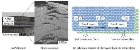
Fig. 7. Correlograms of specimens A and C of the WBFC after three-point bending test: (a) photograph; (b) microstructure; (c) schematic diagram of fibers contributing to tensile stress.
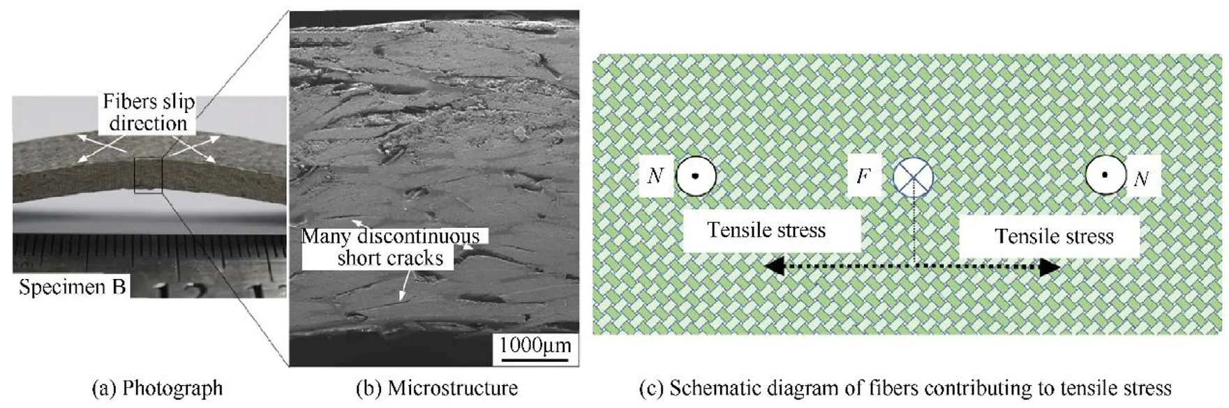
Fig. 8. Correlograms of specimen B of the WBFC after three-point bending test: (a) photograph; (b) microstructure; (c) schematic diagram of fibers contributing to tensile stress.
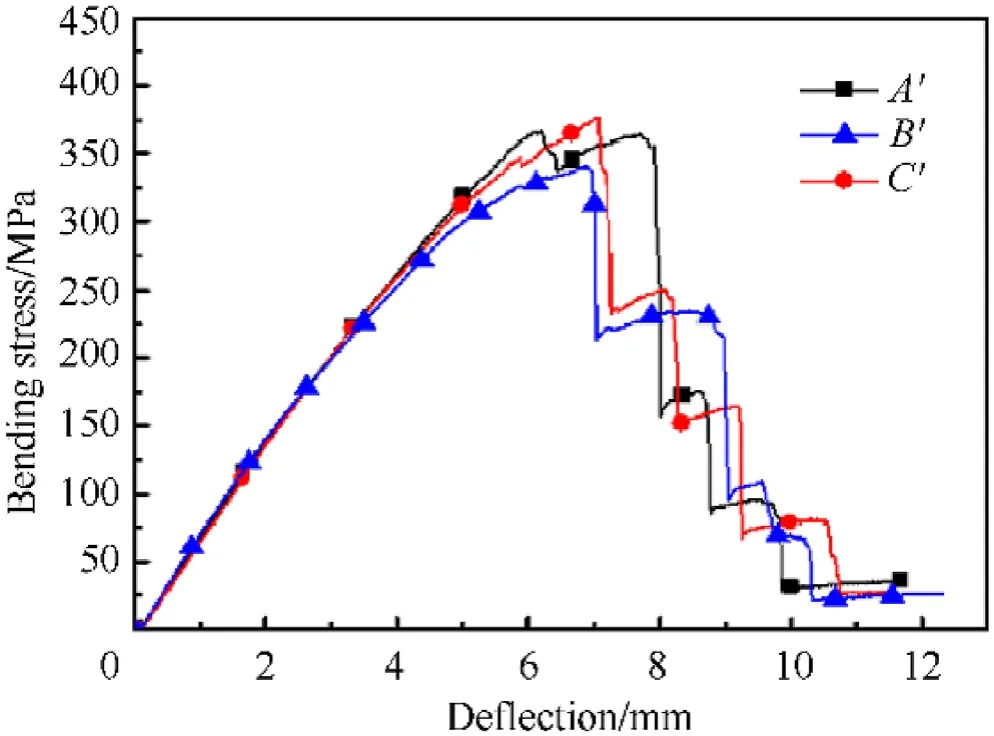
Fig. 9. Three-point bending stress-deflection curves of the UBFC.
Fig.10 is the microphotography of the UBFC after bending. The microstructure of the fracture area demonstrates that the fracture of specimens mainly depends on severe interlayer cracking while there are also some fibers ruptured.When the cracks expand in the interlayer resin, the resistance of the crack extending path along the axial direction of the fibers is the smallest. Furthermore, the fibers of every layer are at different angles, so the cracks need to change the angle to continue to expand from one layer to another.During the cracks expanding with angles changing, the specimen still has a certain bearing capacity, which results in a step-like characteristic of the bending stress-deflection curve until it fails.Fig.10(c)is the schematic diagram of fabrics in the UBFC,and there are a quarter of the fibers parallel to the length direction of the specimens while a quarter of the fibers vertical to the length direction of the specimens. The remaining half of the fibers are at a 45°angle to the length direction of the specimen.This means that a quarter of the fibers are parallel to the tensile stress, and these fibers contribute to resistance to bending deformation, whereas a quarter of the fibers are vertical to the tensile stress, and these fibers make no contribution to resistance to bending deformation.Besides that, half of the fibers make part contribution. Compared with the WBFC, the fibers of the UBFC contributing to the tensile stress are less, leading to lower bending strength of the UBFC.
From the comparison of three-point bending properties of the two composites with different weave and lay-up modes, it can be concluded that both the bending strength and the stiffness of the WBFC surpass those of the UBFC.Therefore,the WBFC show better three-point bending properties.
3.2. Low velocity impact resistance behavior and failure mechanism
The composites used in the protection field may subject to impact under various conditions in practical applications. Therefore,the mechanical response of the composites under low velocity impact are investigated firstly, and the high velocity impact, ballistic test, will be discussed later. The low velocity impact is conducted with two kinds of impactors: the hemispherical impactor and the sharp impactor. The former is a standard impactor of the impact tester and the latter is designed similar to the 12.7 mm armor-piercing projectile core.The low velocity impact with sharp impactor is designed to compare with the ballistic test in the following, that is, to investigate the effect of loading rate on antiimpact and penetration performance of the composites with different weave and lay-up modes. Moreover, the two impactors also simulate the loading condition that the composites are impacted by blunt and sharp objects. The difference of the antiimpact and penetration performance of the composites impacted by blunt and sharp objects will be further discussed.
3.2.1. Low velocity impact test results with hemispherical impactor
When the impactor is hemispherical,there are only two cases of experimental results,perforation or non-perforation.Table 3 shows the results of low velocity impact test with hemispherical impactor.Neither the WBFC nor the UBFC are perforated at 40 J impact energy, but the two composites are both perforated at 60 J impact energy. When the impact energy is 50 J, the UBFC are not perforated, while the WBFC are perforated. Therefore, the UBFC have better impact resistance to hemispherical impactor.
The force-displacement curves of the two composites impacted by hemispherical impactor at 40 J, 50 J and 60 J impact energy are shown as Fig.11.The characteristic trend of the curves reflects the mechanical response of the composites subjected to the low velocity impact with hemispherical impactor at different impact energy. When the impact energy is 40 J, shown in Fig. 11(a), slight fluctuations occur in the forward curves which are due to the destruction of some fibers in the composites. When the curves of the two composites reach the maximum value of the displacement,both begin to fold back, which verifies that the two composite plates are not perforated at 40 J. At the same time, the hemispherical impactor rebounds. At 50 J, shown in Fig. 11(b), as the displacement of the impactor increases to the maximum,the curve of the UBFC folds back, but the curve of the WBFC gradually decrease to a stable value, indicating that the WBFC have been perforated, while the UBFC are still not perforated. The results are consistent with the results in Table 3.At 60 J,as shown in Fig.11(c),the curves of the two composites do not fold back,verifying that the two composites are both completely perforated.
According to prior study,the energy absorbed by the composites can be characterized as the area enclosed by the forcedisplacement curve. In the case of perforation, the area enclosed by the curve and tangent at the end of the curve and is approximately equal to the energy absorbed by the composites, as shown in Fig.11(c).After the low velocity impact tests with hemispherical impactor, the energy absorbed by the composites are calculated shown in Table 4. At the impact energy of 40 J, the maximum impact force of the UBFC is 10.51% higher than that of the WBFC,and the absorbed energy is 5.37%higher than that of the WBFC.The different energy absorption values at the same impact energy indicate that the WBFC have a slightly higher rebound ability. The reason is that both the bending strength and the stiffness of the WBFC surpass those of the UBFC,which can be proved in the threepoint bending experiment above.Since the perforation states of the two kinds of composites at 50 J are different,the energy absorption values are not comparable, so no calculation is performed in Table 4. At 60 J, the maximum impact force of the UBFC is 9.97%higher than that of the WBFC.The energy absorbed by the UBFC is 10.93% higher than that of the WBFC. Even in the case of perforation, the UBFC can consume more impact energy.
When impacted by various types of objects, the composite plates will deform, bulges until break. In general, the higher back convex height, the larger back damage area, and the stronger deformability,the more energy absorption of the composite plates.Therefore, the back convex height and the back damage area are also important factors in characterizing the anti-impact andpenetration performance of the composites. The two composites are not perforated at impact energy of 40 J, while they are both perforated at the impact energy of 60 J.Thus,it is more comparable for back convex height and back damage area at impact energy of 40 J and 60 J,as shown in Table 5.At 40 J,the back convex height of the WBFC is 40%lower than that of the UBFC,and the back damage area is 60.34% smaller than the UBFC. At 60 J, the back convex height of the WBFC is 23.53%lower than that of the UBFC,and the back damage area is 60.88%smaller than that of the UBFC.From the above analysis, it can be concluded that the UBFC have better low velocity impact resistance to hemispherical impactor than the WBFC do.
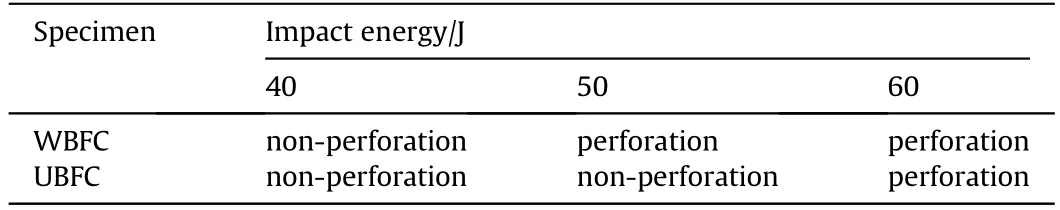
Table 3 Low velocity impact behaviors of the WBFC and the UBFC by hemispherical impactor.
In order to analyze the failure mechanism of the composites during low velocity impact with hemispherical impactor, the fracture morphology of the composites is observed. The composite plates impacted at 50 J and 60 J impact energy are shown in Fig.12 and Fig.13,respectively.It can be seen from Fig.12(a)and(b)that the WBFC are perforated by hemispherical impactor. There is a circular shape destructive morphology on the front and a cross shape on the back. Besides that, some fibers breakage can be observed. As can be seen from Fig.12(c) and (d), the UBFC are not perforated.There is a significant round impactor indentation on the front and approximate rectangular damage area on the back.Notably, it can be observed that the composite plate breaks and delaminates.
When the impact energy is 60 J,as can be seen from Fig.13,the two kinds of composites are both perforated.On the front surface of the plate,as can be seen from Fig.13(a)and(d),the broken holes of the two composite plates are both round, and the sizes of the two broken holes are similar.On the back surface of the plate,as can be seen from Fig.13(b)and(e),many fibers are ruptured,and the back damage area of the UBFC is significantly larger than that of the WBFC.In order to furthermore analyze the failure mechanism and the destruction characteristics of the two composite plates, the specimens after the 60 J energy impact are cut near the broken hole. The cross sections are observed shown in Fig.13 (c) and (f).There is no obvious delamination around the broken hole of the WBFC while a large amount of delamination occurs around the broken hole of the UBFC.
According to the analysis above,the UBFC are more likely to be delaminated during impact compared with the WBFC. The main reason is that the single-layer fabric of the UBFC is a unidirectional fabric structure, and the fiber bundles are not woven with each other, which is conducive for the composites to absorb energy through the fiber layers delamination. Whereas, the fibers of the WBFC are woven together and constrained, leading to the path of the cracks extending along the interlayer direction more tortuous during the impact,which causes the WBFC to be less likely to form delamination. Therefore, the failure of the UBFC is due to delamination breakage and fibers breakage while the main failure mechanism of the WBFC is fibers breakage.Thus,the failure mode of the UBFC are beneficial to higher energy absorption,and higher back convex height as well as larger back damage area are the macro performance of high energy absorption.
3.2.2. Low velocity impact test result with sharp impactor
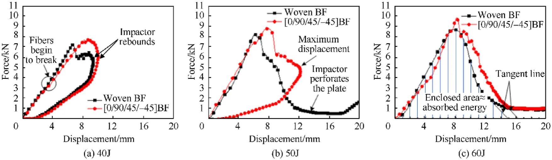
Fig.11. Force-displacement curves of basalt fiber composites impacted by hemispherical impactor at different impact energy: (a) 40 J; (b) 50 J; (c) 60 J.
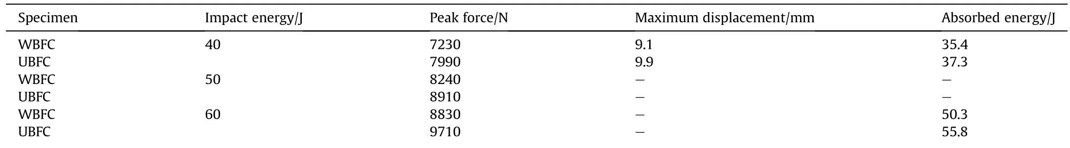
Table 4 Parameters of low velocity impact tests with hemispherical impactor.

Table 5 Back convex height and back damage area of the WBFC and the UBFC after low velocity impact with hemispherical impactor.
The sharp impactor of the low velocity impact is designed similar to the 12.7 mm armor-piercing projectile core of the ballistic tests in order to investigate the effect of loading rate on anti-impact and penetration performance of the composites with different weave and lay-up modes.Furthermore,the differences of the antiimpact and penetration performance of the composites impacted by blunt and sharp objects are investigated by comparing the two impactors with different shape. It should be noted that there are only two cases of non-perforation and perforation with hemispherical impactor, but there are three cases with sharp impactor: non-perforation, semi-perforation and fully perforation.Fig. 14 (a) - (d) is a schematic diagram of semi-perforation with sharp impactor. Although the sharp impactor does not completely perforate the composite plate,a certain size of hole has appeared in the impact point of the composite plate. The typical forcedisplacement curve in the semi-perforation state is shown in Fig.14(e). At point A in Fig.14 (e), the impactor just contacts the composite plate, corresponding to Fig. 14(a). At point B, corresponding to Fig. 14 (b), the force of the impactor reaches the maximum value. At point C, corresponding to Fig. 14(c), the displacement of the impactor reaches the maximum value.At point D, corresponding to Fig.14 (d), the impactor rebounds to the position where it is no longer in contact with the composite plate.
Table 6 shows the test results of the two composites impacted by sharp impactor. It can be seen that both of the two composites are in semi-perforation state at 30 J while completely perforated at 50 J. When the impact energy is 40 J, the WBFC are in a semiperforation state while the UBFC are completely perforated,which indicates that the low velocity impact resistance to sharp impactor of the WBFC is higher than that of the UBFC. Because of the different results of the two composites impacted at 40 J, the following analysis of energy absorption, back convex height and back damage area will not contain the condition of 40 J impact energy.
Same as above analysis of the low velocity impact with hemispherical impactor, the force-displacement curves of the two composites impacted by sharp impactor are analyzed,as shown in Fig.15.It can be seen from Fig.15(a)that when the impact energy is 30 J, the two composites curves are folded back after reaching the maximum displacement, indicating that the impactor has rebounded.The trend of the curve is consistent with Fig.14,which verifies the state of the composite plates is semi-perforation shown in Table 6.At 40 J,as shown in Fig.15(b),the curve of the WBFC is folded back after reaching the maximum displacement while the curve of the UBFC is not folded back,which indicates that the WBFC are semi-perforation,but the UBFC are completely perforated.It can be inferred that the low velocity impact resistance to sharp impactor of the WBFC is higher than that of the UBFC. At 50 J, as shown in Fig.15(c),the curves of the two composites are not folded back, indicating that both of the composite plates are completely perforated.
The energy absorbed by the composites in the low velocity impact with sharp impactor is calculated by measuring the area enclosed by the force-displacement curve, and the results are shown in Table 7. When the impact energy is 30 J, the energy absorption of the WBFC is almost the same as that of the UBFC,which is different from the energy absorption phenomenon of the hemispherical impactor.In addition,the curve of the WBFC has a slightly higher slope than that of the UBFC, which indicates that the stiffness of the WBFC is higher in the elastic deformation period.This is consistent with the study of the three-point bending test results of the two composites.When the impact energy reaches 50 J,it can be seen from Table 7 that the energy absorption of the WBFC is 8.33%higher than that of the UBFC, which also indicates that the low velocity impact resistance to sharp impactor of the WBFC is better than that of the UBFC.
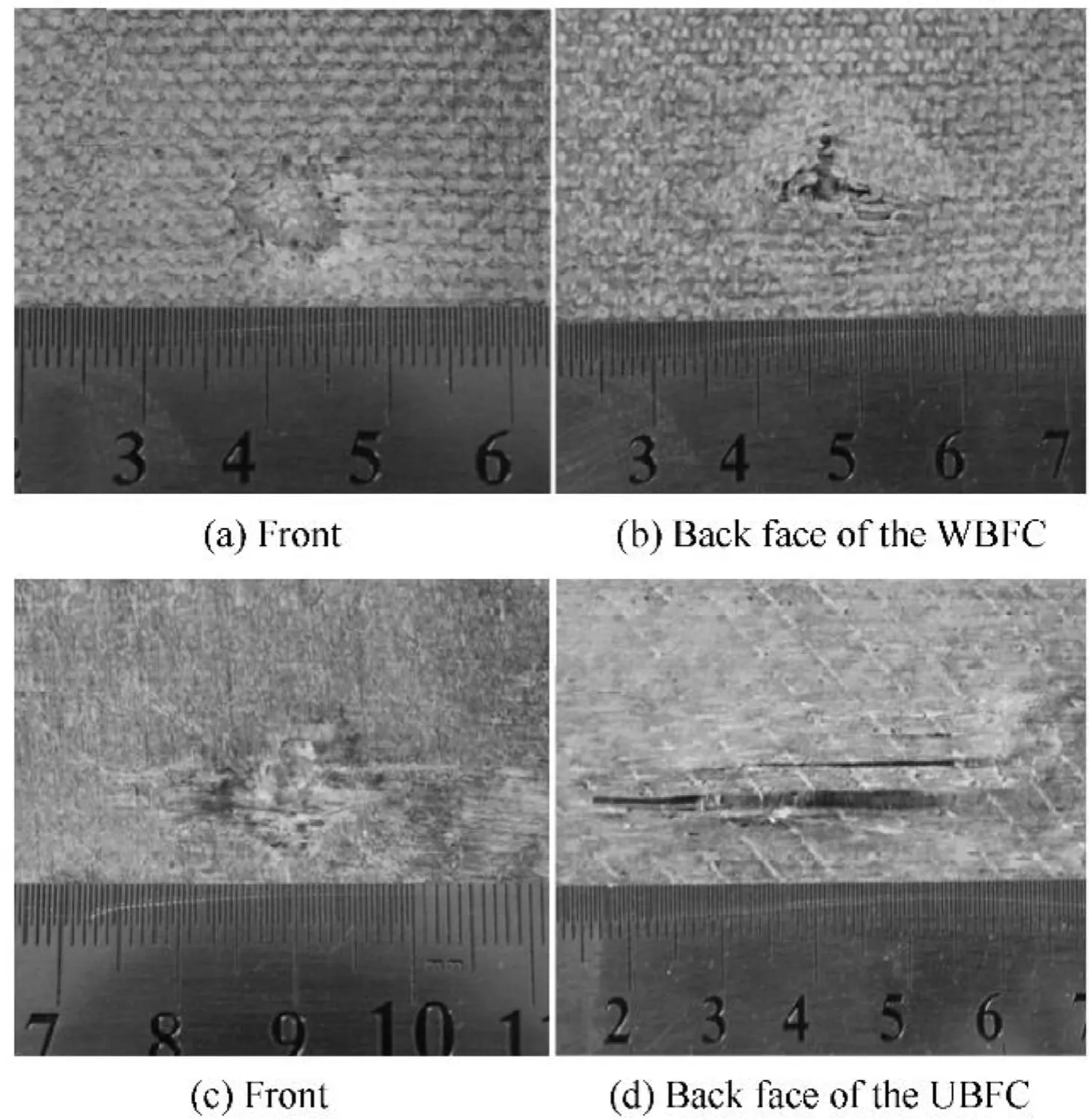
Fig.12. Photographs of damaged composites at 50 J impact energy of hemispherical impactor: (a) front, and (b) back face of the WBFC; (c) front and (d) back face of the UBFC.
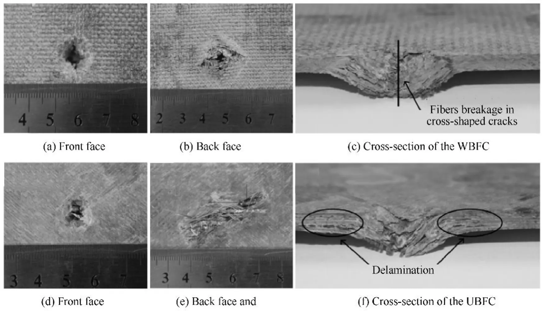
Fig.13. Photographs of damaged composites at 60 J impact energy of hemispherical impactor:(a)front face,(b)back face,and(c)cross-section of the WBFC;(d)front face,(e)back face and (f) cross-section of the UBFC.
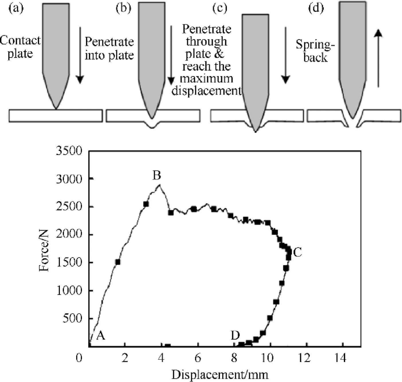
Fig.14. Schematic diagram of semi-perforation of sharp impactor: (a-d) process of semi-perforation, (e) force-displacement curve of semi-perforation.
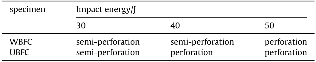
Table 6 Low velocity impact behaviors of the WBFC and the UBFC by sharp impactor.
To further compare the low velocity impact resistance to sharp impactor of the two composites, the back convex height and back damage area of the composite plates at impact energy of 30 J and 50 J are measured,as shown in Table 8. Similar to the low velocity impact with hemispherical impactor,the back convex height of the WBFC is generally lower than that of the UBFC when the two composites are impacted by sharp impactor.So is the back damage area. At 50 J, the back convex height of the WBFC is 54.35% lower than that of the UBFC, and the back damage area of the WBFC is 52.73% smaller than that of the UBFC. It further proved that the UBFC have stronger deformability and ability to absorb energy regardless of the shape of the impactor.
In order to explain the failure mechanism of the two composites impacted by sharp impactor, the fracture morphology of the composite plates impacted by sharp impactor at 50 J are observed in Fig.16.The broken region of the WBFC(Fig.16(a)and(b))shows a cross shape with a large amount of fibers ruptured.From the front side of the UBFC(Fig.16(d)and(e)),it can be seen that there are a large amount of fibers ruptured,but there are only a small amount of fibers ruptured on the back side.Through the above morphology analysis, the failure mechanism can be obtained and shown in Fig. 16 (c) and (f), respectively. Because the fibers are woven together in the WBFC,the sharp impactor perforated the composite plate mainly depending on the breakage of the fibers.However,for the UBFC, the fibers are prone to relative motion due to the unidirectional fabric without mutual weaving constraints between the fibers.Thus,the sharp impactor can perforate the composites easily by squeezing the fibers away without rupturing the fiber bundles.Consequently, the advantage of high axial tensile strength of the fibers is not fully exerted,and the low velocity impact resistance to sharp impactor of the UBFC is inferior to that of the WBFC.
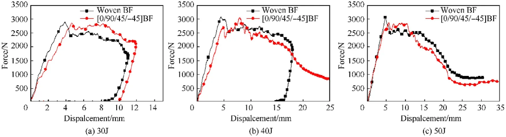
Fig.15. Force-displacement curves of basalt fiber composites impacted by sharp impactor at different impact energy: (a) 30 J; (b) 40 J; (c) 50 J.
Table 7 Parameter of low velocity impact tests with sharp impactor.

Table 8 Back convex height and back damage area of the WBFC and the UBFC after low velocity impact with sharp impactor.

Fig.16. Photographs of damaged composites at 50 J impact energy:(a)front face,(b)back face and(c)schematic of failure of the WBFC;(d)front face,(e)back face and(f)schematic of failure of the UBFC.
The low velocity impact resistance to hemispherical impactor of the UBFC is higher than that of the WBFC in the above research,but when the impactor is sharp, the result is on the contrary. The phenomenon changes due to the change of the failure mechanism when the shape of impactor changes.
When impacted by hemispherical impactor, the composite plates have a large force area.There are fibers breakage both in the UBFC and the WBFC, but the UBFC have more energy absorption.For the UBFC, there is no weaving constraint between the fibers,and they absorb the energy mainly by delamination and the back convex deformation, besides fibers breakage. Whereas, for the WBFC,the fibers are mutually woven and restrained,and the WBFC are difficult to absorb energy through delamination. Furthermore,the stress concentration is easily generated at the fibers lap joint of the WBFC,which results in the impact resistance to hemispherical impactor of the WBFC lower than that of the UBFC.However,under the low velocity impact with sharp impactor, the force area is relatively small, and the number of the fibers ruptured in the two composites is different. The weave and constraint of the fibers are beneficial to the improvement of the anti-impact performance of the WBFC. This is due to the fibers constrained to each other, and the sharp impactor penetrates the composite plate depending on rupturing a large amount of fibers. For the non-woven UBFC, the sharp impactor is easy to squeeze and push the fibers away and perforate directly. The less the fibers break, the less advantages of the high tensile strength of the fibers fully exerted, and the lower the impact resistance to sharp impactor of the composites.Therefore, the low velocity impact resistance to sharp impactor of the UBFC is lower than that of the WBFC.
3.3. Ballistic performance and mechanism
The following research concentrates on the anti-impact and penetration performance characteristics of the two composites under extremely high strain rate loading comparing with low velocity impact with sharp impactor.Table 9 is the ballistic test data of the two composites.It can be seen that when the impact velocity is the same,the residual penetration depth is 25.24 mm of the UBFC,while 26.19 mm of the WBFC.The protection factor DEF of the UBFC is 0.48,which is higher than 0.42 of the WBFC.It can be concluded that the ballistic performance of the UBFC is better than that of the WBFC.
To further analyze the ballistic performance of the two composites, the back convex height and back damage area of the two composites are measured, as shown in Table 10. Both the back convex height and the back damage area of the WBFC are lower than that of the UBFC. The back convex height of the WBFC is 35.35% lower than that of the UBFC, and the back damage area of the WBFC is 52.25% smaller than that of the UBFC.
In order to analyze the failure mechanism of the composites in the ballistic test, the macroscopic morphology of the fracture region of two composites are observed in Fig.17.It can be seen from Fig.17(a),(b),(d),and(e)that there are plenty of fibers breakage in the two composite plates,and the damage area of the UBFC is larger than that of the WBFC.The damage area of the composite plates is cut and the cross section is observed,as shown in Fig.17(c)and(f).The UBFC shows a more serious delamination phenomenon compared with the WBFC.
The failure mechanisms of the two composites under high velocity and low velocity impact condition are compared and analyzed under the same shape impactor. Under low velocity impact, the impact resistance to sharp impactor of the UBFC is lower than that of the WBFC.However,under high velocity impact conditions,the ballistic performance of the UBFC is better than that of the WBFC. This is because the loading rate affects the failure mechanism of the impacted composites when other conditions remain unchanged. This in turn leads to changing in the antiimpact and penetration performance of the composites.
The WBFC are woven and constrained, but there is no weaving constraint in the UBFC, resulting in that the low velocity sharp impactor more easily squeezing the fibers away and directly penetrating the UBFC than the WBFC.However,under high velocity impact condition, the fibers of the UBFC cannot slip in extremely short time,and many fibers are ruptured when impacted by bullets.Thus, the UBFC absorb energy by both fibers breakage and severe delamination, while the WBFC absorb energy by fibers breakage mainly. This leads to that the WBFC have lower ballistic performance than the UBFC do.
By comparing the low velocity impact properties and ballistic properties of the two composites, it can be found that the antiimpact and penetration performance of the basalt fiber composites changes when the loading method changes.Whereas,the back convex height and back damage area of the WBFC are always smaller than those of the UBFC after being impacted by sharpimpactor, hemispherical impactor and bullet. Notably, the protective devices used in human protection are subjected to low velocity impact by sharp impactors such as daggers and bayonets. At the same time, the protective devices are required to have excellent anti-impact and penetration performance as well as small back convex height and back damage area as possible, because the excessively large back convex may cause bone breakdown in the human body. Based on the above analysis, the WBFC are more suitable for personal protection.
Table 10 Back convex height and back damage area of the WBFC and the UBFC after shooting range test.
For armor materials in equipment protection field, it is of great importance to consume as much energy as possible and prevent the damage element from perforating the armor. Therefore, the back convex is allowed and the composites can absorb more energy through the back convex, which is beneficial to improve the protection performance. The UBFC have performance advantages in preventing high velocity bullets. Therefore, the UBFC are more suitable for equipment protection.
4. Conclusion
This study designed and prepared two kinds of basalt fiber reinforced composites, and presented their anti-impact and penetration performance. The mechanical behavior and failure mechanism of the composites were analyzed and discussed under different loading conditions. The following conclusions can be obtained from this article:
a. The effect of weave and lay-up modes on the anti-impact and penetration performance of composites is related to the shape of the impactor. The low velocity impact resistance to hemispherical impactor of the UBFC is higher than that of the WBFC.The absorbed energy by the UBFC is 5.37% higher than that of the WBFC at 40 J impact energy and 10.93%higher at 60 J impact energy.The low velocity impact resistance to sharp impactor of the UBFC is lower than that of the WBFC. The absorbed energy by the UBFC is 7.69%lower than that of the WBFC at 50 J impact energy.
b. The effect of weave and lay-up modes on the anti-impact and penetration performance of the composites is related to the loading rate of the composites.The ballistic performance of the UBFC is superior to the WBFC.The residual penetration depth of the UBFC is 25.24 mm,while it's 26.19 mm for the WBFC,and the protection factor DEF of the UBFC is 0.48, which is higher than 0.42 of the WBFC. However, the low velocity impact resistance of the UBFC is inferior to the WBFC.The absorbed energy by the UBFC is 7.69% lower than that of the WBFC when the two composites are impacted at 50 J impact energy.
c. The failure mechanism of the two composites under different loading method is obtained. When subjected to three-pointbending loading,the UBFC are more prone to delamination,and their bending strength is also lower than that of the WBFC.Under the condition of low velocity impact with hemispherical impactor,the delamination damage of the UBFC is more serious,while the WBFC have a lower degree of delamination and a lower energy absorption. Under the low velocity impact with sharp impactor,plenty of fibers of the WBFC are ruptured in the impact region,while the sharp impactor can easily squeeze the fibers away and perforate the non-woven UBFC directly,and the fibers at the impact region do not completely fracture.Under the high velocity impact by bullet,the fibers of the UBFC cannot be slipped in extremely short time,and the main mode of failure is breakage and delamination damage while the WBFC break mainly through the fibers breakage.

Table 9 Data of basalt fiber composites of shooting range test and calculated protection factor.
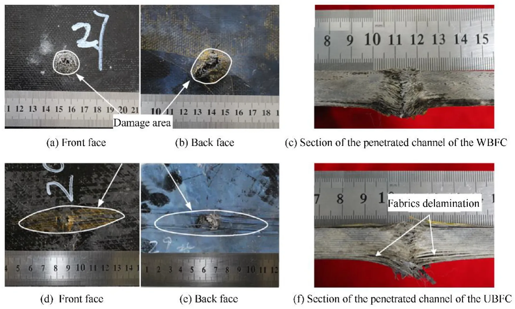
Fig.17. The composite targets after perforating:(a)front face,(b)back face and(c)section of the penetrated channel of the WBFC;(d)front face,(e)back face and(f)section of the penetrated channel of the UBFC.
d. From the low velocity impact test and the ballistic test,the back convex height and the back damage area of the WBFC are smaller than those of the UBFC.The WBFC are more suitable for the personal protection field,and the non-woven UBFC are more suitable for equipment protection field.
Funding
The author(s) disclosed receipt of the following financial support for the research,authorship,and/or publication of this article:This research is supported by the National Science Foundation of China (No. 51571033). This work was supported in part by the National Natural Science Foundation of China under Grant No.11521062.
Acknowledgements
China National Key Laboratory of Science and Technology on Materials under Shock and Impact is acknowledged.
- Defence Technology的其它文章
- Analysis of sliding electric contact characteristics in augmented railgun based on the combination of contact resistance and sliding friction coefficient
- Aerodynamics analysis of a hypersonic electromagnetic gun launched projectile
- Synergistic effect of hybrid Himalayan Nettle/Bauhinia-vahlii fibers on physico-mechanical and sliding wear properties of epoxy composites
- Study on dynamic response of multi-degree-of-freedom explosion vessel system under impact load
- Modeling and simulation of muzzle flow field of railgun with metal vapor and arc
- Path planning for moving target tracking by fixed-wing UAV