
Upgrade of an integrated Langmuir probe system on the closed divertor target plates in the HL-2A tokamak
2022-06-01 07:55ZhihuiHUANG黄治辉JunCHENG程钧NaWU吴娜LongwenYAN严龙文HongbingXU徐红兵WeiceWANG王威策XiangganMIAO苗祥淦KaiyangYI弋开阳JianqiangXU许建强LaizhongCAI才来中ZhongbingSHI石中兵JiaqiDONG董家齐YiLIU刘仪WulyuZHONG钟武律QingweiYANG杨青巍MinXU许敏andXuruDUAN段旭
Plasma Science and Technology 2022年5期
Zhihui HUANG (黄治辉), Jun CHENG (程钧), Na WU (吴娜),Longwen YAN (严龙文), Hongbing XU (徐红兵), Weice WANG (王威策),Xianggan MIAO (苗祥淦), Kaiyang YI (弋开阳) , Jianqiang XU (许建强),Laizhong CAI (才来中), Zhongbing SHI (石中兵), Jiaqi DONG (董家齐),3,Yi LIU (刘仪), Wulyu ZHONG (钟武律), Qingwei YANG (杨青巍), Min XU (许敏) and Xuru DUAN (段旭如)
1 Southwestern Institute of Physics, Chengdu 610041, People’s Republic of China
2 Institute of Fusion Science, School of Physical Science and Technology, Southwest Jiaotong University,Chengdu 610031, People’s Republic of China
3 Institute for Fusion Theory and Simulation,Zhejiang University,Hangzhou 310027,People’s Republic of China
Abstract A newly designed divertor Langmuir probe diagnostic system has been installed in a rare closed divertor of the HL-2A tokamak and steadily operated for the study of divertor physics involved edge-localized mode mitigation, detachment and redistribution of heat flux, etc.Two sets of probe arrays including 274 probe tips were placed at two ports (approximately 180° separated toroidally), and the spatial and temporal resolutions of this measurement system could reach 6 mm and 1 μs, respectively.A novel design of the ceramic isolation ring can ensure reliable electrical insulation property between the graphite tip and the copper substrate plate where plasma impurities and the dust are deposited into the gaps for a long experimental time.Meanwhile, the condition monitoring and mode conversion between single and triple probe of the probe system could be conveniently implemented via a remote-control station.The preliminary experimental result shows that the divertor Langmuir probe system is capable of measuring the high spatiotemporal parameters involved the plasma density,electron temperature,particle flux as well as heat flux during the ELMy H-mode discharges.
Keywords: Langmuir probe, H-mode discharge, HL-2A tokamak, divertor physics
1.Introduction
The divertor Langmuir probe diagnostic system is one of the most important techniques in the magnetic confinement fusion device to diagnose divertor plasma parameters, which can simultaneously provide the ion saturation current density,electron temperature,electron density,particle and heat fluxes with high spatiotemporal resolution [1].In present, the divertor probe diagnostic system has been designed and successfully utilized on many tokamaks,such as EAST[2-4],WEST [5], JET [6], DIII-D [7], ASDEX-Upgrade [8],KSTAR [9], JT-60SA [10] and NSTX [11, 12].The above divertor Langmuir probe systems almost have similar design,the pyrolytic graphite with high heat conductivity is chosen as the material of probe tips,and the probe bodies are embedded into the gaps between the divertor cassettes.In particular,a tungsten divertor Langmuir probe system of the international thermonuclear experimental reactor (ITER) is still continuously optimized in the construction at Southwestern Institute of Physics (SWIP), China.
The previous divertor probe system only with 21 graphite tips has been operated at one port in the HL-2A tokamak since 2005 [13].The triple probe arrays with the vertical resolution of 10 mm can only measure the electron temperature and density in the range of 60 mm.Its insulation performance and reliability are gradually reduced.Moreover,the previous system cannot be competent for the current study of divertor physics related with three-dimensional (3D) physics,the detachment and redistribution of heat flux.Therefore, a new flush-mounted divertor Langmuir probe diagnostic system which has a higher spatial resolution and a wider measurement range has to be designed and installed at two ports of different toroidal positions in the closed lower inner and outer divertor on HL-2A.
This paper mainly presents the design of divertor probe system and the preliminary results measured in the HL-2A ELMy H-mode discharges.This article is organized as follows.In section 2, we describe the probe system and its detailed design.In section 3, we report the preliminary experimental result.Finally, in section 4, we provide the summary and discussion.
2.System description
The HL-2A tokamak with R = 1.65 m and a = 0.4 m is a middle size of the magnetic confinement fusion device,which has been operated at SWIP since 2002 [14].The material of the first wall on HL-2A is graphite, and the target plate in which the cooling water simultaneously flows is made of copper [15].The study of H-mode physics, heat flux control,edge-localized mode (ELM) mitigation and divertor detachment has become one of the major subjects of HL-2A experiments, meanwhile, abundant physical and engineering experimental results have also been obtained in recent years[14, 16].The rare closed divertor configuration of HL-2A tokamak provides a key platform to carry out the advanced divertor researches including the detached physics, the toroidal asymmetry, and so on.
2.1.Design requirements
Based on the above description, it is a very important task to construct a divertor Langmuir probe diagnostic system with the higher spatiotemporal resolution on HL-2A to study divertor physics including the detachment, redistribution of heat flux and so on.In particular,the divertor chamber of HL-2A tokamak is a closed configuration,as shown in figure 1,a very limited spacing for the installation of probe arrays is only with a maximum of 160 mm in vertical direction and 15 mm in radial direction, as indicated by the blue rectangle bars in figure 1,which means that the size and thickness of the probe arrays are seriously limited by the configuration of divertor chamber.Moreover, the probe tips cannot be separately embedded into the gap of the divertor cassettes such as the design of ITER divertor Langmuir probe system,because the copper target plate of HL-2A simultaneously performs the function of water cooling with a width of 20 mm.Main requirements for designing the HL-2A divertor Langmuir probe system are described as follows.

Figure 1.The cross section of the lower divertor of HL-2A tokamak.The limited installation spacing for inner and outer divertor Langmuir probe arrays is indicated by blue rectangle bars.
(1) Probe tips are made of graphite,which is also chosen as the main first-wall material on HL-2A, such as limiter tiles, protection tiles of divertor baffler and dome,protection sleeves of many diagnostics.The probe components must have a good electrical insulation by a novel structure even after large dust deposition and plasma explosion for a long time.
(2) The probe components have to be integrated into a copper substrate plate to avoid modification of the water-cooling system in the divertor target plate of HL-2A,the size of the substrate plate is less than 70 mm in toroidal direction and 160 mm in the vertical direction.
(3) In order to avoid the efficiency dropping of divertor pump system because of blocking off pump flux by the substrate plate, thickness of the plate has to be less than 15 mm.
(4) The vertical resolution in the inner and outer divertor chamber is increased from 10 to 6 mm, so that the divertor detachment and redistribution of heat flux could be carried out [17].
(5) Two sets of probe arrays at two toroidal ports are required to study divertor 3D physics which are induced by lower hybrid waves [18], in-vessel resonant magnetic perturbation(RMP)[19,20],biased electrodes[21]and so on.
2.2.Mechanical design
According to the design requirements, figure 2 presents the schematic principle of a probe body,the components of which are listed from Nos.1 to 6 in figure 2(a).The probe body is composed of the copper substrate plate,a graphite tip,ceramic isolation ring, ceramic support, copper screw and copper latching ring.All components must be manufactured by fine processing and the accuracy is required to reach 0.02 mm.There is a certain number of probe mounting holes in each substrate plate.The material of the probe tip is made of pyrolytic graphite, and the ceramic components are all machined by boron nitride (BN) which is sintered by hot-press technology.There is a M2 female screw with a depth of 3 mm at the back side of a graphite tip.The front end of the copper screw has M2 male screw, but the back end of the copper screw is machined to be a hollow pipe,the inner and outer diameter of the pipe are 0.8 mm and 2 mm, respectively.The copper latching ring is machined to have M11 male screw.

Figure 2.Schematic principle of a probe body in the lower inner and outer divertor chambers of HL-2A tokamak.(a)The components of a probe body are numbered as Nos.1-6,1:the copper substrate plate,2:ceramic isolation ring,3:a graphite tip,4:copper screw,5:ceramic support,6:copper latching ring.The dimensions are labeled,the diameter of the probe tip is 5 mm,the thickness of the substrate plate is only 15 mm.(b) Assembly of a probe body through the rear face of the substrate plate by steps.
The detailed dimensions of the probe components are also labeled in figure 2(a).The dimension of a probe body is φ11×15 mm2.The thickness of the substrate plate is only 15 mm.The probe tip is machined into a flush shape of 6 mm height and 5 mm diameter at the top, as the electron temperature and density in the divertor region are simulated below 60 eV and 1×10¹⁹m-3, so the typical Lamor radius and Debye length are ~0.74 mm and ~20 μm, respectively.The height direction of the probe is parallel to the deposited layers of the pyrolytic graphite so that there is a high thermal conductivity along probe tips.Although the thickness of the ceramic support and ceramic isolation ring is very thin and precise, electrical insulation property of the divertor probe design is very crucial to a lifetime of the system.Insulation resistances of the previous divertor probe systems on HL-2A[13], EAST [2-4], DIII-D [7] and NSTX [11, 12] have generally improved by a labyrinth-like design and increasing the spacing of the gap.However, the newly designed ceramic isolation ring with a simple structure and narrow spacing is easy to manufacture,and the ring could significantly enhance insulation resistance of the gap between the probe tip and the copper substrate plate, even if a large amount of impurity coating and dusts are deposited onto the ceramic surface and the gap for a long experimental operation time [22].
All the components of a probe body are assembled into the probe mounting hole of the substrate plate by six steps,as displayed in figure 2(b).At first, the ceramic isolation ring is inserted into the probe mounting hole from the back side of the substrate plate.Secondly,the graphite tip is tightened with the front end of the copper screw with the M2 screw.In the third step,the connection between the back end of the copper screw and the signal wire is crimped by precision crimping pliers so that the better reliability of electrical conductivity could be guaranteed.In the fourth step, the subassembly including the graphite tip,copper screw and the signal wire is inserted into the probe hole.Then, the ceramic support is in position, where the wire passes through the inner hole of the ceramic piece.Finally, the copper latching ring with M11 male screw is threaded into the probe mounting hole of the substrate plate.Therefore,a probe body is built into the probe mounting hole, and immobilized through the rear face of the copper substrate plate by the copper latching ring.Each substrate plate is integrated many probe bodies, as shown in figure 3.The ceramic support and the ring ensure the electrical insulation between the probe tip and the copper substrate plate.
There are three types of the substrate plates, which are labeled as plates A, B and C.The row spacing of the three plates is all 12 mm.It should be noted that the upper margins of plates A, B and C are 20 cm, 26 cm and 20 cm, respectively.The toroidal width and vertical height of plate A and plate B are 65×160 mm2,there are 33 probe bodies with 11 rows on plate A and 30 probe bodies in 10 rows on plate B,respectively, where probe tip 1, tip 2 and tip 3 in each row could be operated in the single or triple probe mode by the remote control station, which is indicated by a white dotted rectangle in figure 3.The size of plate C with 11 probe bodies is 34×160 mm2,the probe in a row would be only operated in the single probe mode.
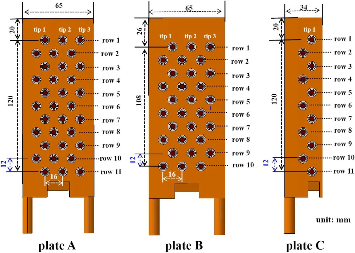
Figure 3.The design drawing of three types of the substrate plate.The plates A and B consisted of 33 and 30 probe bodies,respectively.The probe tips in each row of plates A and B could be operated in the single or triple probe mode,which is indicated by a white dotted rectangle.There are 11 probe bodies in the plate C where the tip in one row would be run in the single mode.
2.3.Installation of the probe system
In order to overcome the space constraint of the HL-2A divertor chamber,figure 4 shows that a set of the probe arrays consisted of plates A, B and C, the upper edges of which are aligned to each other.The signal wires of a substrate plate are organized into two bundles and extracted from the wire guide on both sides of the plates.The substrate plate with a groove at the bottom and two screw holes on the top is inserted and then fixed into the stainless-steel support, which is brazed on the divertor target plate.As discussed in the previous section,the probe tip in a row of plate C is strictly only for the single probe mode.The difference of the upper margin of the plates A and B is deliberately 6 mm, which is half of the row spacing of the plate.The probe arrays could work in two states by combining two plates.The spatial resolution of the first state which is equal to the row spacing of each plate is 12 mm,when probe tips in each row would be separately operated in the single or triple probe mode.In the second state,the spatial resolution of tripe probe arrays would be improved from 12 mm to 6 mm if the plates A and B are combined,where the probe rows of plates A and B are arranged with an interlaced mode.The probe arrays of the combined state would be simultaneously operated in the single or triple mode.Moreover, the spatial resolution of single probe arrays could also be increased to 6 mm if plates C and B are combined.
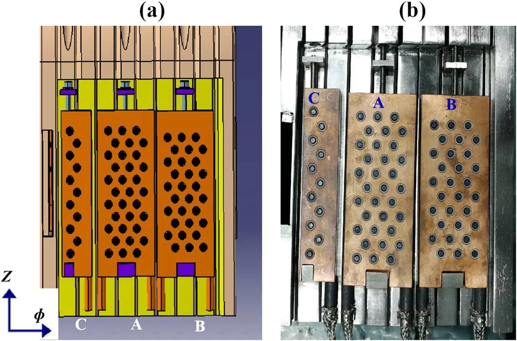
Figure 4.Schematic design(a)and a photo(b)of an integrated probe array in the lower divertor chambers on HL-2A.The toroidal(φ)and vertical (Z) directions of the plates are marked by the arrows.
The vertical positions and toroidal locations of the divertor probe system in the lower divertor chambers on HL-2A are shown in figure 5.In order to study the asymmetry between the inner and outer divertor, the measurement range of the arrays in the inner divertor is from -745 to -865 mm in vertical direction (the minus means below the midplane Z = 0 mm),but the region of the arrays in the outer divertor is covered from-755 to-875 mm.Figure 5(b) displays that two sets of different probe arrays have been placed at two toroidal ports(180°separated toroidally)so that the 3D divertor physics can be implemented on HL-2A.Finally,a summary of the divertor Langmuir probe system is displayed in table 1,There are totally 274 probe tips in the lower inner and outer closed divertor chamber on HL-2A tokamak.

Figure 5.Vertical positions (a) and toroidal locations (b) of the probe arrays in the lower inner and outer divertor chambers on HL-2A.
It is a brief description that the newly designed divertor probe system consists of probe tips, copper substrate plate,stainless steel support, coaxial cables, power supply, signal amplitude modulation unit, data acquisition system and a remote-control station.The copper substrate plate is used to integrate numbers of probe bodies with a high spatial resolution.The signal of each probe tip is transmitted by a coaxial cable.In order to enhance the anti-interference ability, the cables of each substrate plate are bundled with a copper mesh belt.LEMO multipin connectors are used as the vacuum feedthrough of the probe signals.The function of stainlesssteel support is to attach the substrate plate onto the target plate of HL-2A.The power supply of this system often operates in a direct current (DC)mode.The signal amplitude modulation unit is used to adjust the amplitude of probe signal in order to meet the demand of the input voltage±10 V of data acquisition system.The condition monitoring and mode conversion between single and triple probe of the probe system could be conveniently implemented through a remotecontrol software.Data acquisition of 1 MHz with 16 bits is used to acquire the probe signals,the bandwidth and memory depth of the acquisition system are 400 kHz and 16 MSample per channel.The data storage into a data server is carried out via optical fiber, which can electrically isolate the voltage drop between the power supply station and the data server and further protect the divertor probe system.
3.Experimental results
The new integrated flush probe system worked well and provided a lot of reliable data for the study of divertor physics during the last three experimental campaigns.The system primarily works in single and triple probe modes.The floating potential is provided by one of the triple probes,while the othertwo probes work in dual probe mode,which are applied with a 160 V bias voltage.In addition, the following expressions are used to calculate the ion saturation current densityjsat,electron temperatureTet,electron densitynet,particle fulxΓias well as heat fluxqton the divertor target plate [23, 24].
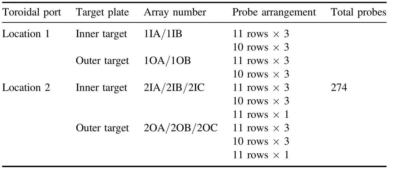
Table 1.A summary of the divertor probe system.

where,Isis a ion saturation current,Apr~1.2 mm2is the effective collection areas of the probe tip,V+is a positively biased potential,Vfis a floating potential,eis the electron charge,miis the ion mass,is the ionacoustic speed at the target,θ=3.5° is the incidence angle between the magnetic field line and divertor target plate,andγis the sheath transmission factor, which isγ~7 for pure deuterium plasma if there is no secondary electron emission andTi=Te[25, 26].
Figure 6 plots the typical discharge parameter evolutions with a lower single null (LSN) divertor configuration in shot 36937, a type-III ELMy H-mode.The plasma parameters of this discharge are shown in figure 6(a), the plasma currentIpis 150 kA, line-averaged electron densityis about 2.0×10¹⁹m-3.Figures 6(b)-(d) display NBI power, LHW power,the plasma stored energy andαD emission in divertor,respectively.Shown in figures 6(e)-(h) including theαD emission, the saturation ion current density and the electron temperature are the zoomed temporal evolutions of plasma parameters measured at the outer divertor plate during the ELM bursts.The strike point position,as shown in figure 6(f),mostly localizes at the Z = -80 ± 0.6 cm.During an ELM phase, the width of the transient particle flux induced by ELMs can reach about 4-5 cm due to large perturbation amplitude.Here, the peak heat flux induced by ELMs is approximately estimated to be about 0.5-1.4 MW m-2using the target electron temperature Te~ (10-20) eV and the current density Jsat= 15-20 A cm-2, which means that the transient heat flux could have a significant effect on damaging the target plate materials.
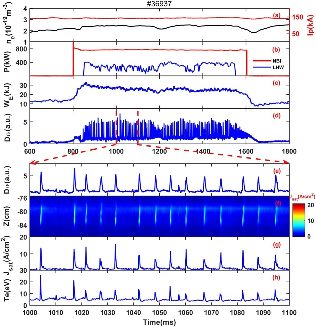
Figure 6.Parameter evolutions for shot 36937 during a type-III ELMy H-mode discharge.Line averaged electron density and plasma current(a),NBI and LHW power(b),stored energy(c)and αD emission(d),the zoomed temporal evolutions of αD emission(e),the saturation ion current density ((f), (g)) and the electron temperature (h) measured at the outer strike point during the ELMs.
The above experimental results demonstrate that the newly designed divertor probe system runs well and can provide the high spatiotemporal divertor parameters on HL-2A tokamak.Up to now, this system has contributed a large amount of experimental data for studying the distribution of ELM induced heat flux[27],the decay length of divertor heat flux [28] and divertor detachment.
4.Conclusions
The new divertor probe system has been successfully applied in the HL-2A experiment.The probe bodies are mounted in the substrate plates with a thickness of 15 mm,and this probe system with 274 tips is highly integrated and has high spatiotemporal resolutions.The whole probe system of flush probe arrays can be conventionally managed by the remote control station for the first time in HL-2A, the probe operation may be easily switched between single and triple probe modes, and the single probe mode can be even worked in direct current (DC) or alternating current (AC)biasing.Furthermore, the reliability including electrical insulation and heat conductivity of the system is abruptly improved because of the novel design of the ceramic isolation ring.
The experimental results represent that this newly designed divertor probe system could provide reliable experimental data for the HL-2A experiment.They have been beneficial for studying the detached divertor physics, the scaling law of the decay lengths Type-I ELM power loads and ELM mitigation [27, 28].In near future, this divertor probe system will make greater contribution to HL-2A physical study, e.g.the heat flux mitigation, strike point splitting physics,detached plasma and toroidal asymmetry of heat flux in the rare closed divertor.We shall also continue to optimize the divertor Langmuir probe design for the application in new fusion device, such as HL-2M tokamak.
Acknowledgments
This work is partially supported by National Natural Science Foundation of China (Nos.11875017, 11875020, 12175186 and 11905052), the National Magnetic Confinement Fusion Science Program of China (Nos.2019YFE03030002,2017YFE0301203 and 2018YFE0310100) and the Sichuan Outstanding Youth Science Foundation (No.2020JDJQ0019).
ORCID iDs
 Plasma Science and Technology2022年5期
- Plasma Science and Technology的其它文章
- Synthesis of Ag-decorated vertical graphene nanosheets and their electrocatalytic efficiencies
- Numerical study of atmospheric-pressure argon plasma jet propagating into ambient nitrogen
- Effects of O2 addition on the plasma uniformity and reactivity of Ar DBD excited by ns pulsed and AC power supplies
- Design and first result of combined Langmuir-magnetic probe on J-TEXT tokamak
- Selective catalytic reduction of NOx with NH3 assisted by non-thermal plasma over CeMnZrOx@TiO2 core-shell catalyst
- A GPU-based general numerical framework for plasma simulations in terms of microscopic kinetic equations with full collision terms