
Argon plume transition from a hollow swell to a diffuse swell with increasing amplitude of a trapezoidal voltage
2022-09-14 08:18JunyuCHEN陈俊宇FurongZHANG张芙蓉PengyingJIA贾鹏英NaZHAO赵娜KaiyueWU吴凯玥JiacunWU武珈存JunxiaRAN冉俊霞XuexiaPANG庞学霞andXuechenLI李雪辰
Plasma Science and Technology 2022年8期
关键词:芙蓉
Junyu CHEN (陈俊宇),Furong ZHANG (张芙蓉),Pengying JIA (贾鹏英),Na ZHAO (赵娜),3,Kaiyue WU (吴凯玥),Jiacun WU (武珈存),Junxia RAN(冉俊霞),Xuexia PANG(庞学霞), and Xuechen LI(李雪辰),,∗
1 College of Physics Science&Technology,Hebei University,Baoding 071002,People’s Republic of China
2 Institute of Life Science&Green Development,Hebei University,Baoding 071002,People’s Republic of China
3 School of Mathematics and Physics,Handan University,Handan 056005,People’s Republic of China
Abstract Atmospheric pressure plasma jets can generate a remote plasma plume,which usually presents a conical or cylindrical morphology.Despite a few morphologies being observed,efforts should be made to obtain more plume structures because streamer dynamics may be revealed from them.For this purpose,an argon plasma plume excited by a trapezoidal voltage is investigated,which presents two kinds of swells (a hollow swell and a diffuse swell)with increasing voltage amplitude(Vp).The results indicate that there are two positive discharges(Dp1 and Dp2)and one negative discharge (Dn) per voltage cycle for both of the swells.With increasing Vp,the inception voltage and discharge intensity increase for every positive discharge,while they decrease for the negative discharge.Fast photography reveals that the positive streamer (Dp2)leaves different tracks in the two swells,which are curved in the hollow swell and randomly branched in the diffuse swell.The different tracks of Dp2 are explained with the consideration of applied field strength and residual positive ions of Dp1.The existence of residual positive ions is finally verified from optical emission spectra.
Keywords: plasma jet,plume morphology,streamer behavior,optical emission spectra
1.Introduction
A plasma jet can generate a remote plasma plume in open space rather than in a confined gap.Thus,it can be used for direct treatment and there is no limitation on the size of the object to be treated[1].Given this advantage,a plasma jet has become a very attractive tool in various application fields,such as surface modification [2–4],biomedicine [5],water purification[6,7],material growth[8],etching[9],and so on.Although a plasma plume fed by inert gas looks continuous to the naked eye [10–13],it is essentially composed of discrete emission layers (also referred to as a plasma bullet) [14],which propagates at a velocity in the order of 103–105m s−1[10,14–16].The fast plasma bullet originates from positive or negative streamers propagating along the working-gas stream [11,13,17].The head of a streamer is a highly effective chemical reactor that can produce active species for diversified applications [16,18,19].The timeintegrated track of streamers is the emission profile (morphology) of a plasma plume,which is one of the major characteristics of a plasma jet [20].Under most circumstances,streamers propagate repeatedly along the stream axis[10,21],leading to a cylindrical plume [14].Due to the inclusion of diffused air,the diameter of repeated streamers decreases with increasing propagation distance,resulting in a solid plume with a conical shape [10].The repeatability of streamers deteriorates with seed electrons left by the previous discharge less than 109cm−3[22,23].That is to say,the solid cone may vary its morphology with decreasing driving frequency.In fact,the solid cone transited to a hollow cone,which originated from the propagation of branched streamers in the interfacial layer between the argon stream and the ambient air[11].At the tail of a conical plume,a fork-like structure was created since streamers tended to follow the neon channel,which was branched by turbulence at plume tail[24].Besides,a feather-like plume was witnessed with argon or helium used as working gas [25,26],which was attributed to dim streamers surrounding the central bright streamer due to Penning ionization.
A striated plume was observed inside the tube of a pulsed argon plasma jet [27].Outside the tube,a striated plume was formed with helium or neon used as working gas [28–30].Droplet striations,also referred to as multiple swells,were formed in an argon or neon plume [31,32],which were attributed to the turbulence of the working gas [33].Multiple swells were formed under a laminar flow[34],which resulted from the periodical diameter variation of propagating streamers due to discharge enhancement by active species.Besides multiple swells,a single swell was produced near the jet nozzle [35],which resulted from the distinct dynamic behaviors of different streamers in one voltage pulse.All in all,streamer dynamics can be revealed through exploring the formation mechanism of plume morphologies.Despite a few morphologies being observed,efforts should be made to obtain more plume structures.
In this work,two kinds of single swells,namely a hollow swell and a diffuse swell,are generated at the argon plume tail excited by a trapezoidal voltage.Using fast photography,distinct streamer dynamics are revealed for the two kinds of swells.
2.Experiment setup
Figure 1 presents a schematic diagram of the experimental setup.The single-electrode jet is composed of a tungsten rod(6.0 cm in length,1.0 mm in diameter,and 0.5 mm in tip radius),which is centered in a glass tube (inner and outer diameters of 5.0 mm and 8.0 mm,respectively).The rod tip is aligned with the nozzle of the jet,which is fed with argon(99.999% purity) after being regulated by a mass flow controller (Sevenstar CS200A).Plume images are captured by a digital camera (Canon EOS 5D Mark IV) with different exposure time (texp).Applied voltage to the jet is detected by a high voltage probe(Tektronix P6015A),which is defined as real voltage (as will be mentioned later).Electric current in the circuit is measured by a coil (Pearson 8600).Waveforms of real voltage and electric current are simultaneously recorded by an oscilloscope (Tektronix DPO4104).Mounted with an intensified charge-coupled devices (ICCD,PI MAX4),a spectrometer (ACTON SP2750) with a grating of 2400 grooves per mm is utilized to collect spatially resolved spectrum through the varying detection position of a fiber.A signal generator (Tektronix AFG 3052C) produces two synchronized 6.0 kHz signals,one of which is a trapezoidal wave used to excite the jet after 2000 times amplification by an up-voltage amplifier (TREK 20/20).The other is a transistor transistor logic(TTL)signal to trigger two independent ICCDs.One ICCD(Andor DH334T)is used to take discharge images and the other ICCD (PI MAX4) is utilized to collect spectrum with short texp.Moreover,the TTL signal is displayed by the oscilloscope along with the current waveform.By subtracting the time lag between the TTL and the electric current,the ICCD can be synchronized with the discharge.Temporally resolved images or spectrum can then be obtained by varying gate moment of the ICCD.
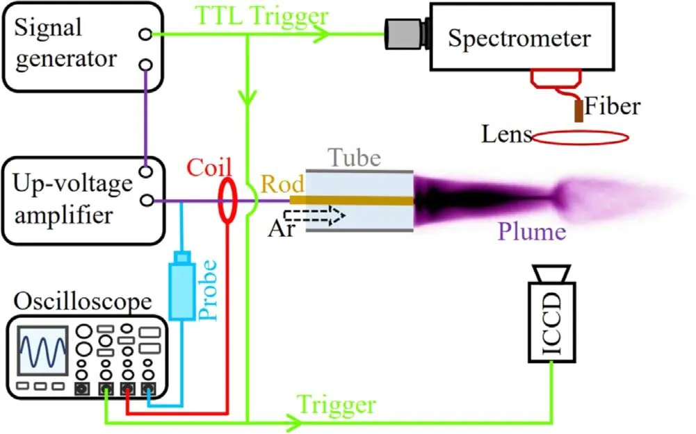
Figure 1.Schematic diagram of the experimental setup.
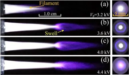
Figure 2.Side-view (left) and end-view (right) images with varying Vp of 3.2 kV (a),3.6 kV (b),4.0 kV (c),and 4.4 kV (d).The endview images are focused on the middle of the swell.Q is 2.0 l min−1,and texp is 0.1 s.
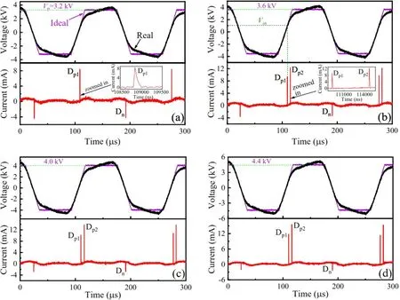
Figure 3.Waveforms of voltage and current.(a)–(d) Corresponding to figures 2(a)–(d),respectively.
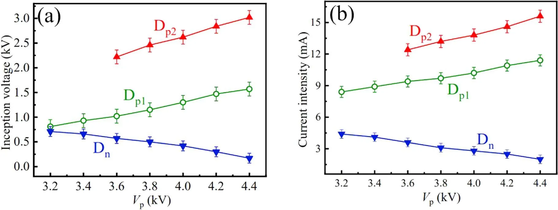
Figure 4.Inception voltage (a) and current intensity (b) of every discharge pulse as functions of Vp.Q is 2.0 l min−1.
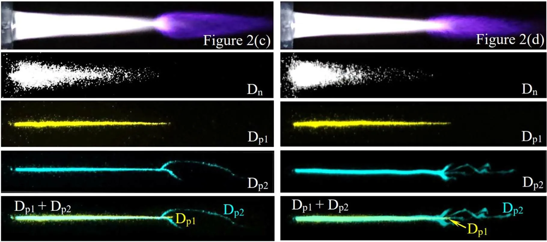
Figure 5.Single-shot ICCD images exposed to Dn,Dp1,and Dp2 for the hollow swell(figure 2(c))(the left)and the diffuse swell(figure 2(d))(the right).The bottom image is the superposition of the two false-color images exposed to Dp1 and Dp2.c.
3.Results and discussion
As presented in figure 2,a diffuse plume with a central filament,similar to that reported previously [12],is firstly generated downstream of the jet nozzle with increasing amplitude of the trapezoidal voltage (Vp).Due to the ingredient of diffused air[10],the plume(3.2 kV)is conical,which elongates along the argon stream with increasing Vp.When Vpreaches 3.6 kV,a purple hollow swell is formed near the plume tail.The hollow structure is clear in the end-view image,where a dim void exists between the purple ring and the central spot.The hollow swell slightly grows with increasing Vp(4.0 kV).The hollow structure disappears and a diffuse swell is formed when Vpsurpasses about 4.4 kV.Hence,two kinds of single swells including the hollow swell and the diffuse swell have been observed at the plume tail.
During the morphology evolution with varying Vp,waveforms of voltage and electric current are recorded,as illustrated in figure 3.Here,the ideal voltage is obtained through multiplying the output of the signal generator by 2000,whose amplitude is the aforementioned Vp.In addition,electric current(discharge current)in figure 3 is obtained from total current by subtracting displacement current,which is directly measured in the circuit when discharge does not initiate without argon flow.Due to the restriction of the amplifier,there is distortion between ideal voltage and real voltage.For this reason,it is impossible to generate a real triangle wave because the triangle apex will be clipped to make it more like a trapezoidal wave.Even though a plume with a well can also be excited by a sinusoidal voltage,there are too many discharge pulses (at least 5 pulses) per voltage cycle,which increases the difficulty in revealing the plume dynamics.Hence,a tailored trapezoidal voltage is used to drive the plasma jet.Obviously,real voltage amplitude increases with increasing Vp.It can be seen in figure 3(a)that there is one positive discharge (Dp1) and one negative discharge (Dn) per voltage cycle for the diffuse plume.Besides,Dp1has a higher intensity than Dn.As indicated in the enlarged current in figure 3(b),the pulse duration is 160 ns for Dp1,200 ns for Dp2,and 240 ns for Dn.The time interval between Dp1and Dp2is about 5.36 μs.For the hollow swell(figures 3(b) and (c)) or the diffuse swell (figure 3(d)),there are two positive discharges (Dp1and Dp2) and one Dnper voltage cycle.Among these discharge pulses,Dp2has the highest intensity.In other words,the number of positive discharges is mainly influenced by Vp,which is one under a low Vpand two with a high Vp.
From figure 3,it can also be found that inception voltage(Vin,absolute value of real voltage when one discharge initiates) and discharge intensity of every discharge change with increasing Vp.Vinwas used to describe partial discharge(also referred to as a dielectric barrier discharge),which is the value of applied voltage when the first discharge initiates during one half cycle.Here,the concept of Vinis used in the discharge of the plasma jet [12,36].For example,Vinof Dp1means the voltage value when Dp1just initiates.Inception voltages and discharge intensities as functions of Vphave been investigated,as illustrated in figure 4.It is found that Vinincreases for Dp1and Dp2,while decreases for Dnwith increasing Vp.Similarly,discharge intensity increases for Dp1and Dp2,while it decreases for Dnwith increasing Vp.
As is well known,streamer regime is involved in plume discharge [12,13,37].Therefore,Dp1and Dp2are positive streamers,while Dnis a negative streamer.The tracks of these streamers are captured by the ICCD,as presented in figure 5.For the hollow swell or the diffuse swell,the negative streamer(Dn)leaves a conical plump track,while the positive streamers (Dp1and Dp2) leave filamentary tracks.In contrast to Dp1,Dp2can propagate a longer distance.Interestingly,Dp2repeats the track of Dp1and leaves a straight line in the left part.In the right part,Dp2tends to detour the tail of Dp1,leaving a curved track that constitutes the hollow swell.However,Dp2tends to cross the tail of Dp1,leaving random branches in the diffuse swell.Accordingly,the distinct morphologies of the hollow swell and the diffuse swell originate from the different propagating behaviors of the positive streamer (Dp2).
Figure 6(a) presents optical emission spectrum scanned from 300 to 800 nm for the hollow swell (a similar spectrum for the diffuse well,hence not shown here).Spectral lines of Ar I (4p→4s transitions) are dominant in the long wavelength range.Besides Ar I,the second positive system of N2(C3Πu–B3Πg) and OH (A2Σ+–X2Π) can also be discerned[38].The intensity ratio of spectral lines (763.7 to 772.6 nm)is positively related to electron temperature,which is determined by electric field strength [39,40].Based on spatiotemporally resolved spectrum,spatial distribution of line intensity ratio(representing field strength)is obtained for Dp2,as plotted in figure 6(b).It can be found that there is a minimal field strength during the propagation of the positive streamer(Dp2)for both of the swells.In contrast to the hollow plume,the diffuse plume possesses higher maximal field strength during Dp2.
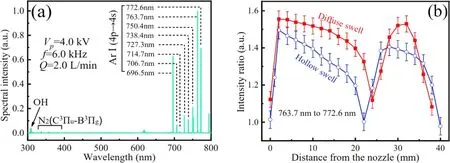
Figure 6.(a) Optical emission spectrum scanned from 300 to 800 nm for the plasma plume (figure 2(c)).(b) Intensity ratio of Dp2 as a function of distance for the hollow swell (figure 2(c)) and the diffuse one (figure 2(d)).
As is well known,charge separation between electrons and positive ions is a prerequisite for a streamer propagation[10].The applied field is reinforced by the induced field of separated charges.In a positive streamer,electrons drift towards and enter the needle anode[12,13,34],leading to the positive current in figure 3.Along with the entering electrons on the anode,the track of the positive streamer is positively charged by residual positive ions,which have been confirmed by numerical simulations[41–43].Although positive ions are considered to be stationary for a positive discharge,this is not the case for a negative discharge,especially near the needle cathode,where positive ions can be accelerated to a high velocity.Through ions bombarding,secondary electrons are produced from the cathode [44],resulting in the negative current in figure 3.It is reasonable to speculate that the track of a negative streamer is negatively charged accompanying the bombarding positive ions and the emitted electrons on the cathode.Before the subsequent discharge,residual electrons in the track can be neglected because of their high mobility.However,electrons can be attached by electronegative species,such as O2,OH,NO,NO2,O,etc to form negative charges [45–49].Compared with electrons,these negative charges have a lower mobility.Hence,a negative streamer can provide the forthcoming streamer with residual negative charges.
Residual negative charges of Dndiminish with increasing Vp,which can be found from the weakening Dnwith Vp(figure 4).Residual negative charges of Dncan lower the field threshold for breakdown of the forthcoming discharge (Dp1)through releasing seed electrons [50,51].Less residual negative charges mean that a higher applied field is needed to initiate Dp1,leading to the rising Vinof Dp1with increasing Vp.As to the increasing intensity of Dp1with increasing Vp,the following two reasons can be considered.Firstly,applied field strength increases with increasing Vp,as mentioned above.A stronger discharge tends to initiate under a higher applied field [52].Therefore,intensity of Dp1increases with increasing Vp.Secondly,because the streamer head of Dp1is positively charged [10,53],residual negative charges can partly counteract or neutralize the charges in the streamer head,which results in the reduction of the induced field.Hence,less residual negative charges mean a higher induced field of Dp1with increasing Vp.That is to say,net field strength of Dp1increases with increasing Vp.As a result,intensity of Dp1increases with increasing Vpbecause discharge intensity of a streamer is determined by net field strength [42].
As a positive streamer,Dp1leaves a positively-charged track[40,41],where residual positive charges become denser with increasing Vpdue to the increasing discharge intensity.The denser residual positive charges produce a higher field opposing the initiation of Dp2.Thus,a higher voltage is needed to initiate Dp2with increasing Vp.Therefore,Vinof Dp2increases with Vp.During the propagation of the positive streamer(Dp2),positive charges left by Dp1can enhance those of the positive streamer head,leading to a higher induced field.Apparently,the induced field increases when residual positive charges get denser with increasing Vp.In combination with the increasing Vin,it can be inferred that net field strength increases with increasing Vp.Hence,discharge intensity of Dp2increases with Vp.
The stronger Dp2provides the forthcoming discharge(Dn) with denser residual positive charges,which produce a higher electric field to help the initiation of Dnafter voltage polarity is reversed.Hence,a lower voltage is needed to initiate Dnas Vpincreases.Consequently,Vinof Dndecreases with increasing Vp.Besides,negative charges in the negative streamer head can be partly counteracted by residual positive charges of Dp2.Hence,less negative charges are presented in the streamer head of Dnwith increasing Vp,which induce a weaker field,leading to the decreasing intensity of Dnwith increasing Vp.
As mentioned before,Dp2has a curved track in the hollow swell.In fact,the curved track was found for a streamer propagating in a tube [54,55],which was attributed to a turbulent flow[54].However,our gas flow is 2.0 l min−1,corresponding to a Reynolds number of 607,which is much lower than that of a turbulent flow[33].Hence,turbulent flow is not the cause for the curved track.The underlying physics of the curved track of Dp2is similar to the snake-like propagation of streamers in a meandering plume [56].In the following,the curved track will be explained from the influence of residual positive charges,which are left in the track of positive streamers [40,41].In fact,residual positive charges are not uniformly distributed in the track,and a large number of them are left at the streamer end where the positive streamer head stops propagating when no more secondary electron avalanches are induced to neutralize the positive streamer head [53].Take Dp1for example,one can deduce that there is a cloud of residual positive ions at the streamer end of Dp1.Due to low mobility of positive ions [57],the cloud of residual positive charges at the streamer end of Dp1can be thought as standing still,which will then influence the propagating behavior of Dp2.
Electric field strength is reduced by the cloud of residual positive charges when the positive streamer (Dp2) is approaching.Maximal field strength will present at the periphery of the cloud,as pointed out by numerical simulations[43,58].Hence,secondary electron avalanches tend to initiate at the locations with maximal field strength[45],and Dp2will be deflected toward the periphery,leading to a curved propagation.When Dp2propagates away from the cloud of residual positive charges,maximal field strength will appear in the stream center leading to the backward deflection of Dp2[43,58].Hence,a curved track is left by Dp2due to its detouring the cloud of residual positive charges left by Dp1.
When the applied field is strong enough (the case of the diffuse swell),field threshold for breakdown can be satisfied in the region near the cloud of residual positive charges even though electric field is reduced by the cloud.In this case,secondary electron avalanches can be induced near the cloud.Hence,the positive streamer(Dp2)crosses the cloud,which is similar to the crossing behavior of surface streamers [40].After crossing the ion cloud(at the right part of the ion cloud),a field is induced by the ion cloud,which is in the same direction as the applied field.Therefore,the electric field is greatly enhanced in the right part of the cloud,so that the field threshold for breakdown can be satisfied in lots of locations after crossing.Resultantly,secondary electron avalanches develop from different locations simultaneously,leading to the random branches of Dp2.This phenomenon is similar to the simulated and experimental results which account for the branching behavior of streamers under a high field [59,60].
As analyzed above,residual positive charges of Dp1can reduce electric field strength when Dp2propagates in their left side.However,field strength is enhanced by them when Dp2propagates in their right side.Hence,a minimal field strength of Dp2appears near the cloud of residual positive charges of Dp1,which is in accordance with the result shown in figure 6(b).
4.Conclusions
In summary,using a trapezoidal wave,two types of single swells,including the hollow swell and the diffuse swell,are generated downstream of a single-electrode argon plasma jet,which present a transition from the hollow swell to the diffuse swell with increasing Vp.Results show that for both of the two kinds of swells,there are two positive discharges and one negative discharge per voltage cycle.With increasing Vp,inception voltage and discharge intensity increase for the positive discharges,while they decrease for the negative discharge.Fast photography reveals that the negative discharge is relatively diffuse and plump,and the positive discharges are filamentary.In addition,the hollow swell comes from the curved propagation of Dp2.In contrast,the diffuse swell results from the branched propagation of Dp2.The different behaviors of Dp2are analyzed after considering residual positive charges of Dp1.From optical emission spectrum,spatial distribution of electric field is obtained during the propagation of Dp2.There is a minimal field strength during Dp2propagation,which confirms the existence of residual positive charges of Dp1.Besides,inception voltage and discharge intensity as functions of Vphave also been qualitatively explained based on residual charges left in the track of the previous discharge.
Acknowledgments
This work is supported by National Natural Science Foundation of China (Nos.51977057 and 11875121),the Natural Science Foundation of Hebei Province,China (Nos.A2020201025 and A2019201100),the Natural Science Interdisciplinary Research Program of Hebei University (Nos.DXK201908 and DXK202011),Post-graduate’s Innovation Fund Project of Hebei Province (Nos.CXZZBS2019023 and CXZZBS2019029),and Post-graduate’s Innovation Fund Project of Hebei University(Nos.HBU2021ss063 and HBU2021bs011).
猜你喜欢
青年文学家(2022年1期)2022-03-11
西江月(2021年3期)2021-12-21
东坡赤壁诗词(2020年5期)2020-11-06
东坡赤壁诗词(2020年5期)2020-11-06
岷峨诗稿(2017年3期)2017-11-25
饮食与健康·下旬刊(2016年9期)2016-05-14
闽台文化研究(2015年2期)2015-04-17
传奇故事(破茧成蝶)(2015年7期)2015-02-28
火花(2015年6期)2015-02-27
火花(2015年5期)2015-02-27
 Plasma Science and Technology2022年8期
- Plasma Science and Technology的其它文章
- Image-based plasma morphology determination and LIBS spectra correction in combustion environments
- Rapid identification of volatile organic compounds and their isomers in the atmosphere
- Fast identification of mural pigments at Mogao Grottoes using a LIBS-based spectral matching algorithm
- Aqueous ruthenium detection by microwaveassisted laser-induced breakdown spectroscopy
- Effect of lens-to-sample distance on spatial uniformity and emission spectrum of flat-top laser-induced plasma
- Quantitative analysis of the main components in ceramic raw materials based on the desktop LIBS analyzer