
A novel fault current limiter topology design based on liquid metal current limiter
2022-09-14 08:18JinjinLI李金金XiongyingDUAN段雄英WeiyingXIE谢为赢ZhihuiHUANG黄智慧MinfuLIAO廖敏夫DequanWANG王德全andXiaotaoHAN韩小涛
Plasma Science and Technology 2022年8期
Jinjin LI (李金金),Xiongying DUAN (段雄英),∗,Weiying XIE (谢为赢),Zhihui HUANG (黄智慧),Minfu LIAO (廖敏夫),Dequan WANG (王德全) and Xiaotao HAN (韩小涛)
1 School of Electrical Engineering,Dalian University of Technology,Dalian 116024,People’s Republic of China
2 Wuhan National High Magnetic Field Center,Huazhong University of Science and Technology,Wuhan 430074,People’s Republic of China
Abstract The liquid metal current limiter (LMCL) is regarded as a viable solution for reducing the fault current in a power grid.But demonstrating the liquid metal arc plasma self-pinching process of the resistive wall,and reducing the erosion of the LMCL are challenging,not only theoretically,but also practically.In this work,a novel LMCL is designed with a resistive wall that can be connected to the current-limiting circuit inside the cavity.Specifically,a novel fault current limiter (FCL) topology is put forward where the novel LMCL is combined with a fast switch and current-limiting reactor.Further,the liquid metal self-pinch effect is modeled mathematically in three dimensions,and the gas-liquid two-phase dynamic diagrams under different short-circuit currents are obtained by simulation.The simulation results indicate that with the increase of current,the time for the liquid metal-free surface to begin depressing is reduced,and the position of the depression also changes.Different kinds of bubbles formed by the depressions gradually extend,squeeze,and break.With the increase of current,the liquid metal takes less time to break,but breaks still occur at the edge of the channel,forming arc plasma.Finally,relevant experiments are conducted for the novel FCL topology.The arcing process and current transfer process are analyzed in particular.Comparisons of the peak arc voltage,arcing time,current limiting efficiency,and electrode erosion are presented.The results demonstrate that the arc voltage of the novel FCL topology is reduced by more than 4.5 times and the arcing time is reduced by more than 12%.The erosions of the liquid metal and electrodes are reduced.Moreover,the current limiting efficiency of the novel FCL topology is improved by 1%–5%.This work lays a foundation for the topology and optimal design of the LMCL.
Keywords:liquid metal current limiter(LMCL),arc plasma,fault current limiter(FCL)topology
1.Introduction
The short-circuit current in a power grid is increasing rapidly,the peak short-circuit current is greater than 100 kA,and the current rise rate di/dt is extremely high.When the short-circuit current approaches or exceeds the existing breaker capacity,the current seriously endangers the safety of the power grid,which thus limits the further development of power grids.Limiting short-circuit currents has become a key challenge [1–4].
Installing a fault current limiter (FCL) is considered a viable solution for reducing fault current [5–7].With the development of FCLs in the past 50 years,a variety have been proposed,including the superconducting fault current limiter(SFCL),solid-state fault current limiter (SSFCL),hybrid fault current limiter (HFCL) and liquid metal current limiter(LMCL),etc.The plus points of the LMCL are its simple structure,automatic detection of current limit,small size,and self-recovery after the fault has been removed.It had taken the combination of the advantages of LMCL and the crisis of the power grid to bring about the adoption of LMCL as a new current-limiting technology with tremendous potential.Several groups have carried out a lot of research and achieved many excellent results [8–10].
To minimize the power loss and fault current in an installed power distribution system,reference [4]studied the optimum placement of distribution generations and fault current limiters in a single-phase.Aiming at use in the highvoltage direct-current field,reference[7]proposed a new type of FCL and its coordination schemes with a direct-current circuit breaker.Referring to [8],a method was proposed of adding the paralleled pure resistance,impedance or another LMCL element to protect the setup from the fault energy concentration in the setup.References [11–14]analyzed the physical process of the pre-arc self-pinching mechanism by building an LMCL simulation model of the insulating wall.To reduce electrode erosion,reference [12]proposed a scheme of embedding ceramic sheets in the electrodes.The effect of different short-circuit currents,LMCL structural parameters and arc plasma pressure on the current-limiting characteristics of the LMCL was experimentally investigated in [15].Referring to [16,17],a current-limiting method combining a fast switch and LMCL was proposed.This method solved the problem that LMCL could not be energized for a long time.So far,no research has been conducted on the pre-arc self-pinch effect,arc characteristics,and current-limiting characteristics of liquid metal for the LMCL’s resistive materials wall.
In this work,based on the liquid metal self-pinch effect,a novel LMCL with a resistive wall inside the cavity is designed.The resistive wall can be connected to the current-limiting circuit.The new FCL topology is designed using the novel LMCL in series with a fast switch,and then in parallel with the current-limiting reactor.This work uses the fluid simulation software Fluent.A three-dimensional mathematical model of the liquid metal self-pinch effect is established.Gas-liquid twophase distribution diagrams of the pre-arc liquid metal selfpinch effect under different short-circuit currents are obtained from the simulation.A series of experiments are carried out with an LC oscillation circuit as the power supply.A highspeed camera is used to capture the dynamic process of the liquid metal arc plasma.Combining the images of the arc with the experimental waveforms,the arc plasma characteristics and the current transfer process are analyzed.This work divides the arcing process into the following four stages: arc extension stage,arc enhancement stage,arc weakening stage and arc extinguishing stage.Next,according to the L branch current rise rate di/dt and LMCL branch current trend,the current transfer process from LMCL branch to L branch is divided into four stages,as shown in figure 1.Finally,this work compares the peak arc voltages,arcing times,current limiting efficiencies,electrode erosion of the novel FCL topology,and the LMCL of the polymethyl methacrylate (PMMA) wall,respectively.The novel FCL topology can decline the arcing time and arc voltage,increase the current limiting efficiency,suppress the violent burn of the arc,and reduce the erosion of the liquid metal and the electrodes.This proves the effectiveness of the novel FCL topology.It provides a basis for the practicability of the LMCL.
2.Novel LMCL and novel FCL topology design
2.1.Novel LMCL design
2.1.1.LMCL principle.Figure 2 shows the principle of the LMCL’s liquid metal self-pinch effect.According to [3,8,18–20],the magnetic flux density B and Lorentz force Fmagin the channel cross section are greater than those outside the channel,because when the current flows through the liquid metal,the current density is not uniformly distributed along the axial direction.However,when a short-circuit fault occurs,the current and Fmagof the liquid metal in the channel rise significantly,hence the column of liquid metal shrinks rapidly under the current action to form depressions.
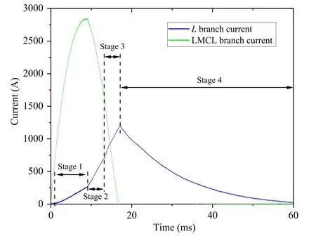
Figure 1.Current transfer diagram.Stage 1 is the LMCL branch current start transfer stage,stage 2 is the LMCL branch current transfer acceleration stage,stage 3 is the LMCL branch current transfer weakening stage,and stage 4 is the L branch current drop stage.

Figure 2.The principle of the liquid metal self-pinch effect [3].
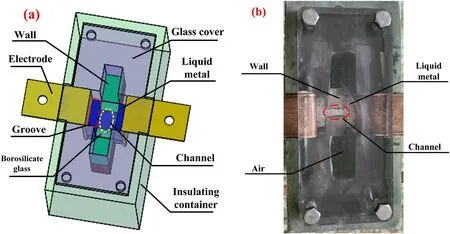
Figure 3.Three-dimensional view and physical top view of the novel LMCL.(a) Three-dimensional view,and (b) physical top view.
Referring to [15,21],according to the Lorentz force formula,the systolic pressure generated in the radial direction of the aperture is
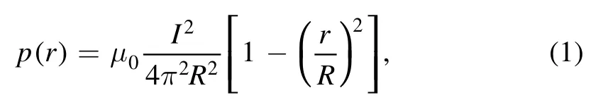
where p(r) is the radial systolic pressure,I is the current,r is the distance between the calculation point and the channel axis,R is the flow aperture andμ0is the vacuum permeability.
2.1.2.Novel LMCL design.Figure 3 is the three-dimensional view and physical top view of the novel LMCL proposed in this work.The insulating container is a rectangular parallelepiped structure made from epoxy resin.The outer dimension is 100 mm × 200 mm × 200 mm.The LMCL’s top is a transparent glass cover to prevent liquid metal droplets from splashing.It is also convenient,in order to use a high-speed camera to photograph the dynamic process of the liquid metal under the action of current.There are two identical grooves on the left and right sides of the wall.The size of each groove is 10 mm × 40 mm × 150 mm.L-type copper electrodes are placed on both sides of the grooves and connected to the external circuit.There is a Kovar 4J29 material wall inside the device that can be flexibly removed.There is a cylindrical channel inside the wall.The diameter and length of this cylinder are 10 mm and 20 mm respectively.GaInSn is used as the liquid metal,which fills the grooves and channel.A borosilicate glass is bonded on the channel to form a closed space,which is convenient for observing the dynamic process of the liquid metal.The rest of the cavity is air.
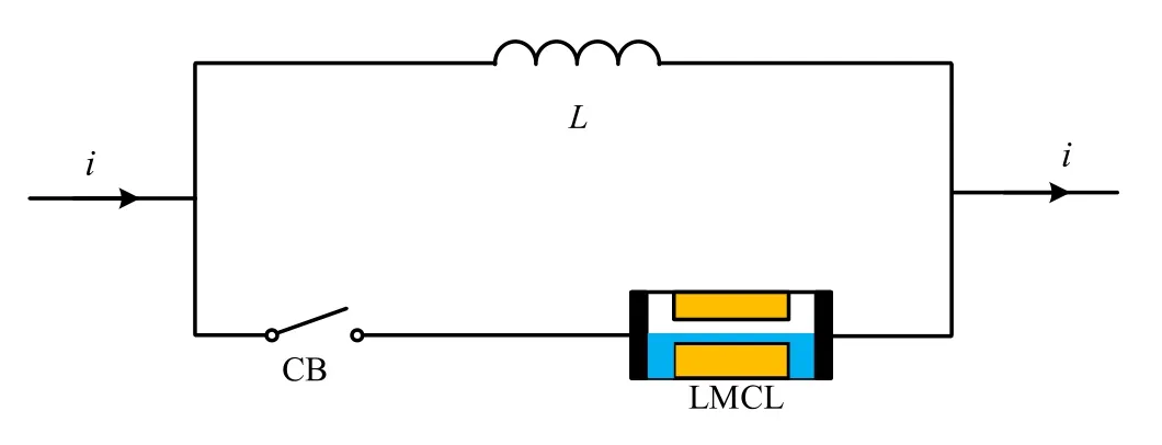
Figure 4.The novel FCL topology.L is a current-limiting reactor,CB is a fast switch,and LMCL is the novel LMCL designed in figure 3 [3].
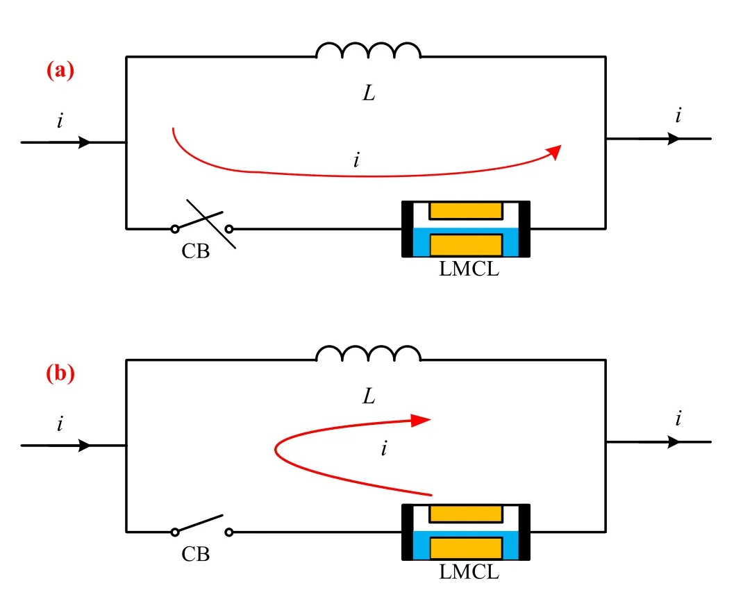
Figure 5.The current flow diagrams of the novel FCL topology.(a)Normal operation,and (b) short-circuit fault.
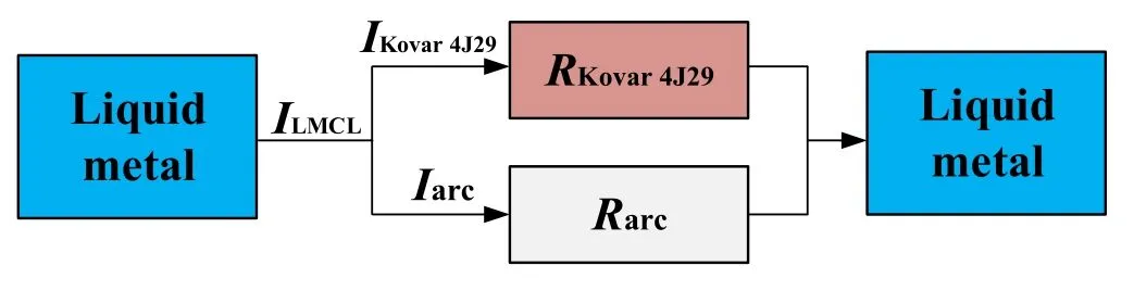
Figure 6.The novel LMCL internal current distribution diagram.Current flows in the left groove.ILMCL is the total current flowing through LMCL branch.RKovar 4J29 is the wall resistance.Rarc is the total arc resistance.RKovar 4J29 and Rarc are connected in parallel in the channel to share ILMCL.
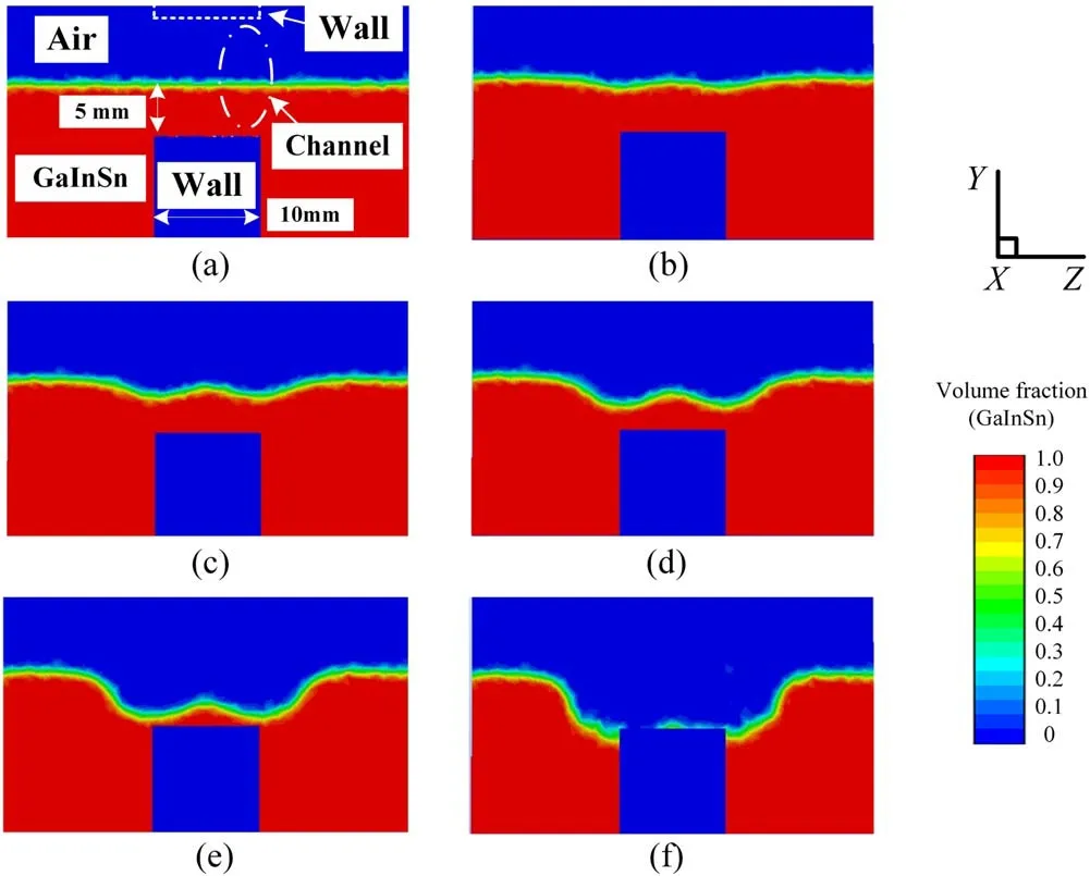
Figure 7.The gas-liquid two-phase dynamic distribution diagram of the liquid metal self-pinching process where the short-circuit current is 1.5 kA.(a)t=0 ms,(b)t=1.65 ms,(c)t=2.2 ms,(d)t=2.75 ms,(e) t=3.3 ms,and (f) t=3.85 ms.
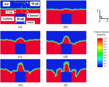
Figure 8.The gas-liquid two-phase dynamic distribution diagram of the liquid metal self-pinching process where the short-circuit current is 3 kA.(a) t=0 ms,(b) t=0.8 ms,(c) t=1.2 ms,(d) t=2 ms,(e) t=3 ms,and (f) t=3.16 ms.
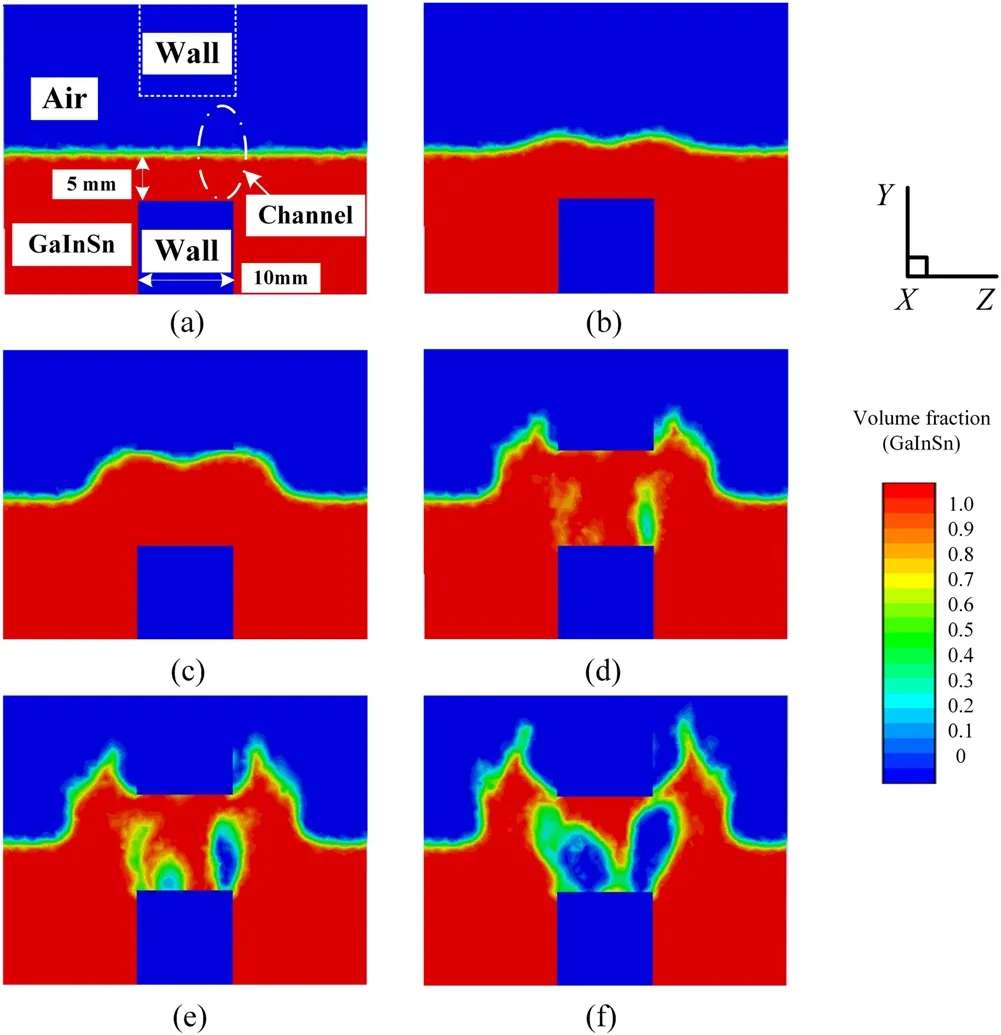
Figure 9.The gas-liquid two-phase dynamic distribution diagram of the liquid metal self-pinching process where the short-circuit current is 10 kA.(a)t=0 ms,(b)t=0.74 ms,(c)t=1.3 ms,(d)t=1.94 ms,(e) t=2.13 ms,and (f) t=2.46 ms.

Figure 10.Schematic diagram of the novel FCL topology experimental circuit.CB,LMCL,and L are the novel FCL topology designed in figure 4.S is the main switch that controls the discharge of capacitor C.C,L1,and D constitute the experimental power supply.Among them,C is a power supply capacitor bank with a capacitance value of 0.341 F.L1 is a power supply reactor with an inductance value of 186.6 μH.T1,B1,R1,R2 and K constitute the capacitor bank charging circuit.Among them,T1 is a transformer;B1 is a rectifier bridge;R1 and R2 are current-limiting resistors;K is a charging circuit breaker [3].
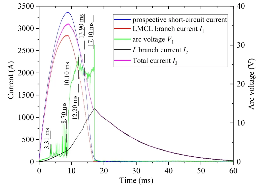
Figure 11.The waveform diagram is obtained from the experiment.The blue curve is the prospective short-circuit current.The green curve is the arc voltage V1.The red curve is LMCL branch current I1.The black curve is the L branch current I2.The purple curve is the total current I3.
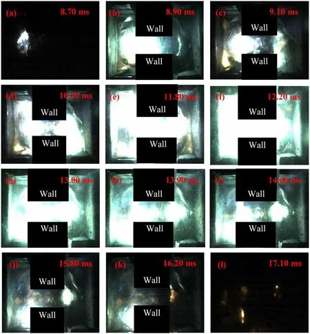
Figure 12.The liquid metal arc plasma diagrams.
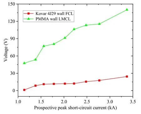
Figure 13.Comparison chart of the peak arc voltage.The red curve and the green curve are the peak arc voltages of the Kovar 4J29 wall FCL and the PMMA wall LMCL respectively.
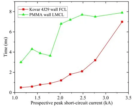
Figure 14.Comparison chart of the arcing time.The red curve and the green curve are the time between the first peak and the second peak of the arc voltages of the Kovar 4J29 wall FCL and the PMMA wall LMCL,respectively.
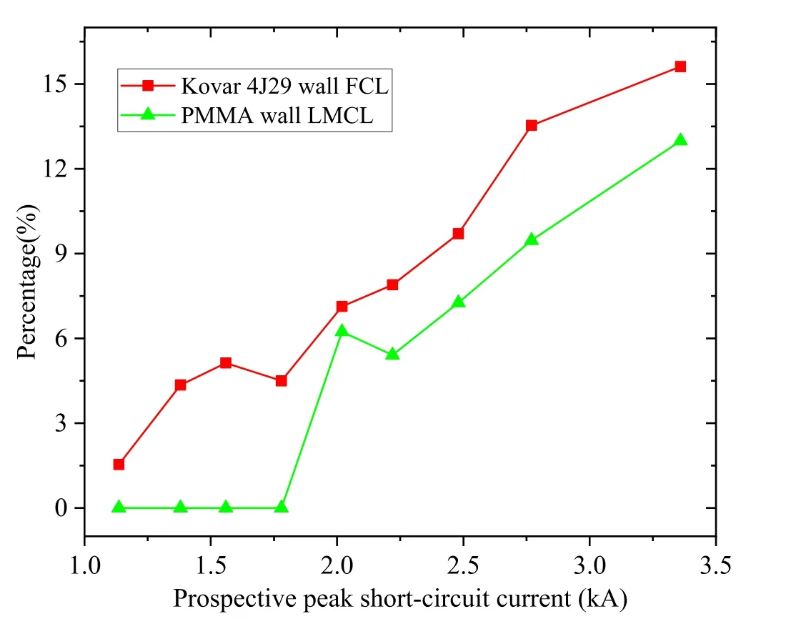
Figure 15.Comparison chart of the current limiting efficiency.The red curve and the green curve are the current limiting efficiencies of the Kovar 4J29 wall FCL and the PMMA wall LMCL respectively.
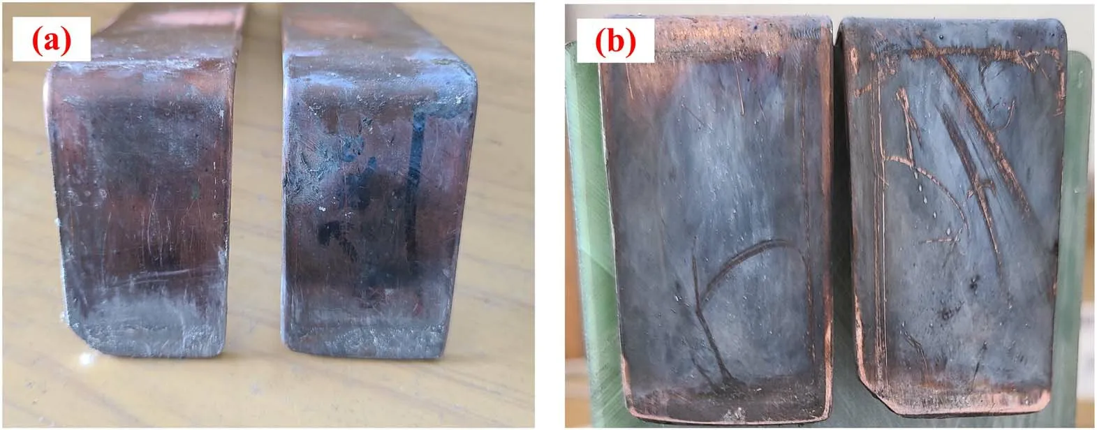
Figure 16.After the experiments,the electrodes of the Kovar 4J29 wall FCL are compared with those of the PMMA wall LMCL.(a) The electrodes of the Kovar 4J29 wall FCL,and (b) the electrodes of the PMMA wall LMCL.
When the system is in normal operation,the current in the LMCL flows through one electrode,liquid metal,and the other electrode.When the channel is filled with liquid metal,the resistance of the LMCL is 50.6 μΩ,and the loop impedance is almost zero.However,when short-circuiting,the liquid metal burns as an arc,thus the liquid metal arc plasma resistance and wall resistance (resistive material) are connected to the loop.As soon as the short-circuit fault is removed,the liquid metal can return to the channel again.
The main chemical composition of Kovar 4J29 is Fe–Ni–Co.The conductivity of Kovar 4J29 is 2.08 × 10⁶S m−1,and the magnetic permeability is 2 × 10⁻³T·mA−1.The volume of Kovar 4J29 selected in this work is 50 mm × 20 mm ×50 mm.The chemical properties of Kovar 4J29 have good corrosion resistance in the atmosphere,fresh water,and sea water,and it has excellent processing,welding,and electroplating properties,suitable as a component of a power system.In addition,Kovar 4J29 does not react with mercury,etc,and is suitable for use in instruments containing liquid metal discharges [22].Moreover,the equipment that Kovar 4J29 connects with glass has high strength,pressure resistance and corrosion resistance.Most importantly,Kovar 4J29 has special expansion characteristics.It has a similar expansion coefficient and thermal expansion &contraction rate with the borosilicate glass on the upper part of the channel during heating and cooling.Therefore,it can be firmly attached and sealed with borosilicate glass to prevent the glass from cracking during the experiment [23].
2.2.Novel FCL topology design
2.2.1.Novel FCL topology design.At present,the currentlimiting technology of the LMCL takes advantage of series arc plasma,which cuts down the application of the FCL in practical engineering[16].The novel FCL topology proposed combines this with the characteristics of a converter FCL and variable impedance FCL.This topology can reduce arcing time,arc voltage and erosion,and can increase the current limiting efficiency,equipment life,and current-limiting times.The topology of the device is shown in figure 4.
In normal operation,the current flow of the novel FCL topology is as shown in figure 5(a).CB is closed and the resistance of the LMCL approaches zero,so the system current passes through the LMCL branch,and the loss of the system is minimal.When a short-circuit fault occurs,the current flow of the novel FCL topology is as shown in figure 5(b).Once short-circuiting,the resistance of LMCL rises rapidly.The fault current limiter starts to limit current,and the current i starts to transfer from LMCL branch to the L branch.When the controller detects the fault signal,the fast switch CB is opened,and the current i is accelerated to transfer to the L branch.When the current of the LMCL branch crosses zero,the fault current is all transferred to the current-limiting reactor L.
The main roles of the LMCL in the novel FCL topology are as follows.(1) The time when the current limit starts is advanced.When the LMCL burn arc starts,the novel FCL topology begins to limit current.Compared with the topology mode of the traditional FCL in [24](the current-limiting reactor L is connected in parallel with the fast switch CB),the current-limiting start time is much earlier.(2) Short-circuit faults are quickly identified.Detecting the voltage across the LMCL,combined with the current Recursive Least Square(RLS),the short-circuit fault can be quickly and accurately identified.
Compared with the existing insulating material wall LMCL design [8–18,20,25],the novel LMCL designed in this work does not need to bear the short-circuit current for too long because of the current transfer and the fast switch CB is opened in the case of a short circuit.Therefore,the liquid level of the liquid metal should not be too high,which can increase its sensitivity to short-circuit current.Simultaneously,because the arc strength of the novel LMCL is low,the difficulty of designing the cavity can be reduced,so that more materials can be used in the design of the LMCL.
There are four advantages and innovations of the novel FCL topology,which are as follows.(1) The current limiting efficiency is improved.In this work,the current limiting efficiency of the novel FCL topology is compared with an existing LMCL.It can be found that the current limiting efficiency of the novel FCL topology is improved by 1%–5%compared with the existing LMCL.(2) LMCL erosion is reduced.Because of the current transfer,the LMCL branch current is reduced,which can effectively reduce LMCL erosion.(3) The speed of current-limiting is faster.When the resistance of the LMCL rises,the current transfers from the LMCL branch to the current-limiting reactor.Compared with the fast-switching FCL in[24],the novel FCL topology has a much earlier current-limiting start time.(4)LMCL application areas are added.At present,the current limiting of the LMCL makes use of a series of arc plasma,the greater the number of the series,the better the current-limiting effect,which is suitable for low-voltage applications.The novel FCL topology utilizes the LMCL,CB and L in cooperation,which lifts the LMCL into the field of high-voltage current-limiting.
2.2.2.Theoretical analysis of the novel FCL topology to reduce erosion.The novel FCL topology designed in figure 4 can effectively reduce the erosion of the liquid metal and electrodes because of the resistive wall structure inside the LMCL and the current transfer enabled by the topology.Two factors are specifically analyzed below.
Based on the actual structure of the LMCL,several experimental waveforms and liquid metal arc plasma images are combined.When the arcs of the grooves and channel are connected,the internal current distribution of the novel LMCL is as shown in figure 6.
According to Kirchhoff’s law (KVL) and Kirchhoff’s current law (KCL),the Kovar 4J29 branch current IKovar4J29is deduced as
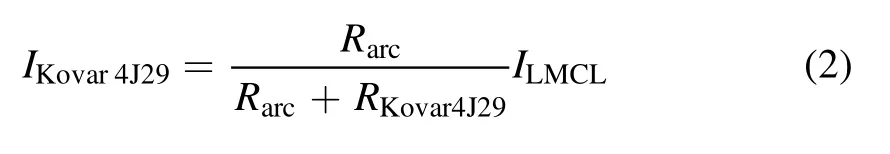
Referring to [10,15,18],during the arcing process,as the liquid metal arc increases,the arc resistance gradually increases.Referring to equation (2),as the arc resistance increases,the current in the Kovar 4J29 branch gradually increases.The current flowing through the arc resistance branch of the novel FCL is reduced compared to the insulating material used as a wall inside the cavity in[8–18,20,25].By changing the material of the wall from insulating to resistive,the novel LMCL can limit the violent burn of the liquid metal arcs.
In figure 5(b),the controller causes CB to quickly open,and the LMCL branch current can be transferred to the current-limiting reactor L.Compared to the LMCL singlebranch current limiting design in[5,10–15,18–20],the novel FCL topology designed in this work can utilize the current transfer to reduce the LMCL branch current.Therefore,the violent burn of the arc can be further suppressed by using the novel LMCL with a fast switch to current transfer.
3.Simulation of the liquid metal self-pinching process
In the published literature,the liquid metal self-pinching process of the insulating wall was simulated,to prove that the liquid metal self-pinch effect in the channel of the resistive wall is still effective.Aiming at the LMCL designed in figure 3,this work uses the simulation software Fluent for modeling and simulation calculation [22].Comprehensive consideration is given to the interaction of the gas-liquid twophase flow field and the electromagnetic field.Based on the analyses of the characteristics of the fluid in the liquid metal self-pinching process,this work establishes a three-dimensional mathematical model of the liquid metal self-pinch effect on the free surface [11–14,26].This mathematical model combines the fluid volume method model,the turbulence model and the magnetohydrodynamic model.
In order to simplify the calculation,this work simplifies the simulation model.In this simulation,the height of the liquid metal level from the channel bottom is 5 mm,and liquid metal does not fill the entire channel.The wall has a cylindrical channel.Both the diameter and length of this cylinder channel are 10 mm.The right electrode and the left electrode are the anode and cathode respectively.The shortcircuit current half-wave time is 15 ms,and the peak shortcircuit current values are 1.5 kA,3 kA,and 10 kA,respectively.The dynamic distribution diagrams of the gas-liquid two-phase at different moments on the Y-Z symmetry plane of the corresponding geometric model are shown in figures 7,8 and 9.In the following simulation diagrams,the red color is GaInSn liquid metal,the upper blue color is air,and the blue color wrapped in red is the Kovar 4J29 wall.
It can be seen from figure 7 that at 1.65 ms,the liquid metal-free surface on both sides of the wall begins to shrink.Two depressions are formed.The depressions are recessed toward the bottom of the channel,and the liquid level of the grooves on both sides rises.With the increase in time,the depressions continue to deepen and expand.At 3.3 ms,the depressions reach the bottom of the channel,and there is still a small amount of liquid metal in the center of the channel.At 3.85 ms,a small amount of liquid metal of the channel is squeezed into the grooves.The liquid metal in the channel is broken,forming arc plasma.
It can be seen from figure 8 that at 0.8 ms,the liquid metal-free surface begins to show a shrinking trend.Then the free surface continues to dent slowly towards the bottom of the channel.At 1.2 ms,the depressions of liquid metal continue to extend.At the same time,the liquid metal level in the channel rises.At 2 ms,the depressions reach the bottom of the channel and continue to develop outside the channel.At 3 ms,two new depressions appear on both sides of the wall and extend downward.The new depressions squeeze liquid metal near the sides of the wall.Due to being squeezed,the liquid metal level rises.At 3.16 ms,the four depressions reach their maximum and fractures are formed,resulting in the formation of the arc plasma.Three liquid columns,one tall and two short,are formed in the channel and on both sides of the wall.Currently,the right free surface depression is deeper than the left.
It can be seen from figure 9 that at 0.74 ms,the liquid metal-free surface in the center of the channel and on both sides of the grooves begins to shrink.Liquid metal inside the channel is squeezed and moves upwards,forming an M shape.As time increases,the liquid metal level in the channel gradually rises.At 1.94 ms,the channel is completely filled with liquid metal.Concurrently,the liquid metal level on both sides of the wall is higher than in the channel.Two bubbles form on both sides of the wall and begin to burn arc.At 2.13 ms,the bubble on the right gradually expands,and two bubbles are formed on the left.At 2.46 ms,the right bubble continues to expand,and the two bubbles on the left merge into a large bubble.The right bubble is larger than the left one.The liquid level on the right side of the wall is slightly higher than that on the left side.
To sum up,some laws can be found.(1) During the liquid metal self-pinching process,the greater the current,the higher the liquid metal-free surface is squeezed up.(2) The positions where the liquid metal-free surface begins to depress are different with various currents.This will lead to different forms of bubbles.When the current is small,the liquid metalfree surface begins to shrink on both sides of the wall and forms bubbles.As the current increases,the liquid metal-free surface in the channel and the grooves begins to shrink.As a result,the channel is filled with liquid metal,and bubbles are formed inside the channel.(3) As the current increases,the time when the liquid metal-free surface starts to shrink and liquid metal breaks in the channel gradually decreases,resulting in earlier arcing time.(4)Although the forms of the bubbles are different under various currents,arc plasma begins to form on both sides of the wall.
4.Experiment
4.1.Experimental circuit diagram
Using the novel FCL topology diagram (in figure 4),the experimental circuit diagram of the novel FCL topology is as shown in figure 10.
In figure 10,the currents (I1,I2) and voltage signal (V1)are recorded with an oscilloscope.I3is the experimental total current.An LC single-frequency oscillation circuit is used to simulate a short-circuit fault.Varying the charging voltage of the capacitor bank C gives the short-circuit current needed for the experiment.
Before the start of the experiment,ensure that the main switch S is open and the fast switch CB is closed.When the charging circuit switch K is closed,the capacitor bank C is charged.As soon as the capacitor bank C reaches the test voltage,K is opened.The main switch S is closed,after which the LC power supply discharges.The controller triggers the high-speed camera to capture the dynamic process of the liquid metal arc plasma.After that,the controller sets CB to open,and the current of LMCL branch is gradually transferred to the L branch.
4.2.Results and discussion of the arcing process and the current transfer process
This work uses the novel FCL topology experimental circuit shown in the schematic diagram of figure 10 to carry out this experiment.The liquid metal level height from the channel’s bottom is 5 mm.The value of the current-limiting reactor L is 108.6 μH.The prospective short-circuit current is the current measured by the direct discharge of the LC power supply without load.Assume that the main switch S is closed completely at time zero.The open time of CB is at 9.12 ms in this experiment.When the charging voltage of capacitor bank C is 130 V,the corresponding peak short-circuit current is 3.37 kA.The waveform diagram obtained from the experiment is shown in figure 11.
In this experiment,the liquid metal arc plasma of the LMCL is photographed by a Motionpro series high-speed camera,and the shutter speed is 20000 fps.The light intensity and shooting angle of the camera are continuously adjusted.When the controller triggers the camera,it captures the arc plasma as shown in figure 12.
4.2.1.Results and discussion of the arcing process.When the peak short-circuit current is expected to reach 3.37 kA,figures 11 and 12 show the experimental waveforms and arc plasma dynamic change during the liquid metal arcing process.According to the change of arc plasma shape and the liquid metal pre-arc characteristics obtained by the simulation in figures 7–9,combined with the change trend of the short-circuit current and arc voltage,the arcing process can be divided into the following four stages: arc extension stage,arc enhancement stage,arc weakening stage and arc extinguishing stage.The changes of the arc plasma and voltage in each stage are introduced below.
Referring to figures 12(a)–(d),the time from 8.70 ms to 10.10 ms is the arc extension stage.At 8.70 ms,an arc is burned on the left side of the wall,and it extends and expands to the right in the channel.As the arc expands,the brightness also increases.At 9.10 ms,the right arc also starts to burn,and then extends and expands to the left in the channel.At 10.10 ms,the arcs extending on the left and right sides are connected in the channel.During the arc development stage,the arc voltage is divided into two increasing stages,because of the different arc starting times on both sides of the wall.The arc voltage of the first stage is increased from 1.48 V to 13.12 V in a sudden change.After 0.23 ms,the second arc voltage jumps from 13.34 V to 21.48 V.
Referring to figures 12(d)–(f),the time from 10.10 ms to 12.20 ms is the arc enhancement stage.In this stage,the arc in the channel remains connected.The arc continues to expand,and the brightness gradually increases.At 12.20 ms,the arc intensity reaches its maximum.During the arc enhancement stage,as the arc strengthens,the arc voltage gradually increases.The arc voltage reaches the first peak of 27.51 V.
Referring to figures 12(f)–(h),the time from 12.20 ms to 13.90 ms is the arc weakening stage.At this stage,although the arc in the channel is still connected,the arc begins to shrink and becomes thinner,and the brightness gradually decreases.At 13.90 ms,the arc in channel is disconnected.During the arc weakening stage,the arc voltage gradually decreases,from the first peak voltage of 27.51 V to 22.95 V.
Referring to figures 12(h)–(l),the time from 13.90 ms to 17.10 ms is the arc extinguishing stage.At this stage,after the arcs break in the channel,the arcs shrink,their brightness diminishes and gradually extinguishes.At 16.20 ms,the right arc extinguishes first.At 17.10 ms,the left arc is then extinguished.At this stage,the arc voltage first drops and then rises.At 16.20 ms,the arc voltage jumps down to 18.40 V.Then,the arc voltage gradually increases due to the influence of the voltage across the current-limited reactor L and the arc of CB not being extinguished.At 16.90 ms,the current crosses zero,and the arc voltage rises to 24.34 V.Subsequently,the arc voltage jumped to 30.11 V.At 17.10 ms,all of the arcs are extinguished,and the arc voltage drops to zero instantaneously.
In summary,according to the change of arc plasma shape,arc plasma development is divided into four stages,and the arc plasma development is closely related to the change of arc voltage.In the arc extension stage,the arc voltage increases in two steps.In the arc enhancement stage,the arc voltage continues to increase and reaches the first peak.In the arc weakening stage,the arc voltage slowly drops.In the arc extinguishing stage,the arc voltage first drops and then rises.Finally,as the arc extinguishes,the arc voltage plummets to zero.
4.2.2.Results and discussion of current transfer process.This work does not use the liquid metal arc plasma to limit the current but uses the novel LMCL to cooperate with CB to transfer the short-circuit current from the LMCL branch to the L branch.According to the change trend of the LMCL branch current I1,the L branch current I2,the arc plasma shape,and the arc voltage in figure 11,the current transfer process from the LMCL branch current I1to the L branch can be divided into the following four stages: the current start transfer stage,the current transfer acceleration stage,the current transfer weakening stage,and the current I2drop stage.The following section describes the current changes in each stage.
The time from 0.96 ms to 8.70 ms is the current start transfer stage.At 0.96 ms,the current begins to transfer due to the increased arc voltage.Then,the phenomenon of arcing and extinction with the arc voltage less than 10 V occurred multiple times.The LMCL branch current I1starts to transfer to the current-limiting reactor L because multiple arcs are burning.The current I2increases almost linearly,and the current rise rate di/dt=17.602 A ms−1.
The time from 8.70 ms to 13.90 ms is the current transfer acceleration stage.Starting at 8.70 ms,the arc plasma starts to burn on both sides of the wall and inside the channel.At 9.15 ms,CB begins to open and burn arc.At 13.90 ms,the liquid metal arcs in the channel are disconnected.At this stage,affected by the enhancement of the arc plasma between liquid metal and CB,the LMCL branch current I1accelerates to transfer to the current-limiting reactor L.The increase rate of the current I2reaches maximum,it is almost linear.The current rise rate di/dt=112.784 A ms−1.
The time from 13.90 ms to 17.10 ms is the current transfer weakening stage.At this stage,the liquid metal arcs are disconnected and enter the extinguishing stage.At the same time,the CB arcs have also entered a weakening stage.At 16.90 ms,the current I1crosses zero.Subsequently,at 17.10 ms,the liquid metal arcs and the CB arcs are extinguished.There is no current in the LMCL branch,and all the current is transferred to L.The current I2reaches a maximum of 1.202 kA.At this stage,affected by the arc plasma weakening between the liquid metal and CB,the transfer speed of the LMCL branch current I1to the current-limiting reactor L decreases.The increase rate of the current I2is almost linear and the current rise rate di/dt=108.621 A ms−1.
The time from 17.10 ms to 60.00 ms is the current I2drop stage.At this stage,the LMCL branch current I1is zero.The current has all been transferred to the L branch.It takes 42.90 ms for the current I2to slowly drop to zero.
In summary,the current transfer process from the LMCL branch current I1to the L branch can be divided into four stages.Moreover,the current rise rate is an important parameter to describe the current transfer process.In the current start transfer stage,the current I2rise rate is small.In the current transfer acceleration stage,the current I2rise rate reaches its maximum.In the current transfer weakening stage,the current I2rise rate is declined.In the I2current drop stage,the LMCL branch current is zero,and I2slowly drops to zero.
4.3.Comparison of the novel FCL topology with existing LMCLs
The wall material in figure 3(a) is replaced with PMMA to simulate an existing insulating wall LMCL [8–18,20,25].The existing insulating wall LMCL is named the PMMA wall LMCL in this section.PMMA has excellent arc resistance.The surface of PMMA does not produce carbonized conductive pathways and arc tracing phenomena under the action of an arc [27].Using the LC oscillation circuit power supply in figure 10,the PMMA wall LMCL is discharged.The liquid metal level height from the channel’s bottom is 5 mm.The experimental data under different short-circuit currents are obtained by varying the charging voltage of capacitor bank C.
The above experimental results of the PMMA wall LMCL are compared with those obtained from the novel FCL topology in figure 4.The novel FCL topology is named the Kovar 4J29 wall FCL in this section.The following section is a comparison of the peak arc voltage,arcing time (the time from the first peak arc voltage to the second peak),current limiting efficiency,and electrode erosion respectively.
4.3.1.Comparison of the peak arc voltage.The trend diagram of peak arc voltages of the PMMA wall LMCL and Kovar 4J29 wall FCL under different short-circuit currents is shown in figure 13.
According to figure 13,the peak arc voltages of the PMMA wall LMCL and the Kovar 4J29 wall FCL both show an increasing trend.Further,the PMMA wall LMCL has a faster peak arc voltage increase speed than the Kovar 4J29 wall FCL.
When the prospective peak short-circuit current value is 1.56 kA,the peak arc voltages of the PMMA wall LMCL and Kovar 4J29 wall FCL are 77.1 V and 11.1 V,respectively.The voltage difference is 66 V,and the peak arc voltage of the Kovar 4J29 wall FCL is reduced by 5.30 times.
When the prospective peak short-circuit current value is 3.37 kA,the peak arc voltage of the PMMA wall LMCL is as high as 140.1 V,while the Kovar 4J29 wall FCL is only 24.34 V.The voltage difference is as high as 115.76 V,and the peak arc voltage of the Kovar 4J29 wall FCL is reduced by 4.76 times.
In summary,the arc voltage of the Kovar 4J29 wall FCL is significantly lower than the PMMA wall LMCL.The peak arc voltage of the Kovar 4J29 wall FCL is reduced by more than 45 V,and the reduction is more than 4.5 times.
4.3.2.Comparison of arcing time.Under different shortcircuit currents,the arcing times (the time from the first peak of the arc voltage to the second peak) of the PMMA wall LMCL and Kovar 4J29 wall FCL topology are shown in figure 14.
According to figure 14,as the short-circuit current increases,the arcing time of the PMMA wall LMCL first increases,and then remains unchanged.The arcing time of the Kovar 4J29 wall FCL shows an increasing trend,and the increasing speed gradually increases.Moreover,the PMMA wall LMCL has a greater arcing time than the Kovar 4J29 wall FCL.
When the prospective peak short-circuit current value is 2.02 kA,the arcing times of the PMMA wall LMCL and the Kovar 4J29 wall FCL are 6.8 ms and 1.2 ms,respectively.The difference between the two times is 5.6 ms,and the arcing time of the Kovar 4J29 wall FCL is reduced by 4.67 times.
When the prospective peak short-circuit current value is 3.37 kA,the arcing times of the PMMA wall LMCL and Kovar 4J29 wall FCL are 7.9 ms and 7 ms,respectively.The difference between the two times is 0.9 ms,and the arcing time of Kovar 4J29 wall FCL is reduced by 12.9%.
In summary,the arcing time of the Kovar 4J29 wall FCL is significantly shorter than that of the PMMA wall LMCL.The arcing time of the Kovar 4J29 wall FCL has been reduced by more than 0.9 ms,a reduction of more than 12%.
4.3.3.Comparison of the current limiting efficiency.In this work,the current limiting efficiency is defined as
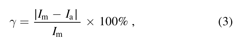
where γ is the current limiting efficiency,Imis the prospective peak short-circuit current value,and Iais the actual peak current value of the LMCL branch.
The variation trends of the current limiting efficiencies of the Kovar 4J29 wall FCL and the PMMA wall LMCL under different short-circuit currents are shown in figure 15.
It can be seen from figure 15 that when the PMMA wall LMCL is less than 2.02 kA,the current limiting efficiency is zero.Because the current is small,arcs will occur after the current peak.It has no effect on the current peak,so the current limiting efficiency is zero.When the current is 2.02 kA,the current limiting efficiency increases from 0% to 6.93%,then declines slightly.As the current increases,the arcing time gradually advances,the arc voltage also increases,and the current limiting efficiency also increases.At 3.37 kA,the current limiting efficiency reaches its maximum value of 12.99%.
The current limiting efficiency of the Kovar 4J29 wall FCL increases almost linearly with increasing current.At 3.37 kA,the current limiting efficiency reaches its maximum value of 15.61%.The arcing time advances as the current increases and current transfers,which leads to the increase in the current limiting efficiency.
In summary,when the short-circuit current is less than 2.02 kA,the current limiting efficiency of the PMMA wall LMCL is zero.However,the Kovar 4J29 wall FCL has an effect on limiting peak current at any current.The current limiting efficiency of the Kovar 4J29 wall FCL is about 1%–5% higher than that of the PMMA wall LMCL.At 1.56 kA,the current limiting efficiency difference reaches its maximum,which is 5.13%.However,at 2.02 kA,the smallest current limiting efficiency difference is only 0.90%.
4.3.4.Comparison of electrode erosion.The electrodes of the Kovar 4J29 wall FCL are shown in figure 16(a),after hundreds of experiments.The electrodes of PMMA wall LMCL are shown in figure 16(b),after dozens of experiments.
It can be seen from figure 16(a)that the electrodes of the Kovar 4J29 wall FCL directly opposite to the channel position have only slight erosion.In addition,a few white smoke-like particles remain on the surface of the electrodes.It can be seen from figure 16(b) that the electrodes of the PMMA wall LMCL are severely ablated.The longer the liquid metal arcing time and the greater the arc voltage,the more serious the liquid metal erosion will be.This results in a large number of white smoke-like particles remaining on the electrodes surface.
The novel LMCL uses Kovar 4J29 as the wall material of the cavity,and the novel FCL topology controls CB to quickly open and transfer current.These can reduce the arcing time and arc voltage,suppress the violent burn of the arc,and reduce the erosion of the liquid metal and electrodes.
5.Conclusion and future trends
The concept of the LMCL is quickly taking root not only on the agendas of policy makers,but also in the research community.An LMCL,by definition,should be operational both while current-limiting multiple times and with only slight erosion.Consequently,it is essential to design a new topology such that it performs satisfactorily in operation.
In this work,simulations of the liquid metal self-pinching process in the channel of the resistive wall find the cause of arc plasma formation and the dynamic change laws of liquid metal.During the liquid metal self-pinching process,the positions where the liquid metal-free surface begins to depress are variable under the action of different currents,which leads to different forms of bubbles.As the current increases,the time when the liquid metal-free surface starts to shrink and liquid metal breaks in the channel gradually decreases,resulting in an earlier arcing time.Although the forms of the bubbles are different under various currents,arc plasma begins to form on both sides of the wall.Therefore,it is effective for the liquid metal self-pinch effect under the condition of a resistive wall.
In addition,the novel FCL topology,in which the novel LMCL,fast switch,and current-limiting reactor are combined to reduce the erosion of liquid metal and electrodes,is proposed.The approach is tested on an LC single-frequency oscillating power supply.The experimental results show that the arc development is closely related to the change in arc voltage.Furthermore,the current rise rate is different for each stage in which the LMCL branch current I1transfers to the L branch.In the current transfer acceleration stage,the maximum rise rate of current I2is almost linear due to the enhanced arc of liquid metal and CB.The results of the arcing process and current transfer process highlight the effectiveness of the proposed method.
Furthermore,the novel FCL topology and existing LMCL of four typical current-limiting parameters,i.e.,arcing time,arc voltage,current limiting efficiency,and electrode erosion,are discussed and compared respectively.The experimental results show that the peak arc voltage of the novel FCL topology is reduced by more than 4.5 times,and the arcing time is reduced by more than 12%.Thus,the novel FCL topology suppresses arc burning violently and reduces the erosion of the liquid metal and electrodes.Concurrently,the current limiting efficiency of the novel FCL topology is improved by 1%–5%.
A key issue that requires further investigation in the future is whether a cylindrical channel of the novel LMCL can be replaced with other shapes or multiple quantities.Moreover,further work would carried out to replace the wall materials with other materials that are more suitable for such a system.
Finally,the applications of the LMCL will be greatly extended.In particular,the penetration of the LMCL into field of high-voltage current-limiting is expected to experience rapid growth in the near future.
Acknowledgments
This work was supported by National Natural Science Foundation of China (Nos.51777025,52177131) and the Interdisciplinary Program of the Wuhan National High Magnetic Field Center (No.WHMFC202130),Huazhong University of Science and Technology.
猜你喜欢
学前教育(幼教版)(2019年9期)2019-12-30
快乐作文(3.4年级)(2019年9期)2019-09-10
故事作文·低年级(2019年3期)2019-03-18
作文与考试·小学低年级版(2019年2期)2019-01-31
小天使·一年级语数英综合(2014年6期)2014-07-22
小学生导刊(中年级)(2014年4期)2014-05-09
智慧与创想(2013年7期)2013-11-18
网球俱乐部(2009年9期)2009-07-16
数学大王·低年级(2009年5期)2009-05-31
数学大王·低年级(2009年5期)2009-05-31
 Plasma Science and Technology2022年8期
- Plasma Science and Technology的其它文章
- Image-based plasma morphology determination and LIBS spectra correction in combustion environments
- Rapid identification of volatile organic compounds and their isomers in the atmosphere
- Fast identification of mural pigments at Mogao Grottoes using a LIBS-based spectral matching algorithm
- Aqueous ruthenium detection by microwaveassisted laser-induced breakdown spectroscopy
- Effect of lens-to-sample distance on spatial uniformity and emission spectrum of flat-top laser-induced plasma
- Quantitative analysis of the main components in ceramic raw materials based on the desktop LIBS analyzer