
Effect of the withdrawal rate on the microstructure and creep behavior of the directionally solidified nickel-based superalloy
2023-03-30 08:35YizheYngZhixunWenHiqingPeiYunsongZhoXipengYinShuishuiWngZhufengYue
Yizhe Yng, Zhixun Wen,*, Hiqing Pei,**, Yunsong Zho, Xipeng Yin,Shuishui Wng, Zhufeng Yue
a School of Mechanics, Civil Engineering and Architecture, Northwestern Polytechnical University, Xi'an, 710072, PR China
b Science and Technology on Advanced High Temperature Structural Materials Laboratory, Beijing Institute of Aeronautical Materials, Beijing, 100095, China
Keywords:Directionally solidified nickel-based superalloy Withdrawal rate Microstructure Creep K-R creep damage model
A B S T R A C T The effect of the withdrawal rate on the microstructure and creep behavior of a directionally solidified nickelbased superalloy DZ125L is investigated in this study.A directionally solidified nickel-based superalloy is directionally solidified using the high rate directional solidification (HRS) process at various withdrawal rates.The results show that the closely packed dendrite arms and well distributed γ′ phase can significantly enhance the creep rupture life of the alloys, while the carbides and γ/γ′ eutectics affect the strength failure and fracture of materials.A series creep tests are performed on the nickel-based directionally solidified superalloy after different withdrawal rates.With an increasing withdrawal rate,the creep life of the alloy first increases and then decreases.The K-R creep damage model is established, which can reflect the quantitative relation between the withdrawal rate and creep life.The model simulation results are in good agreement with the tests.
1.Introduction
Directionally solidified nickel-based superalloys without transverse grain boundaries have been widely used in critical gas turbine components because of their excellent high temperature properties[1-3].HRS is essential as a method to produce industrial preparation of directionally solidified blades.It can be described as the process in which a ceramic mould containing molten materials is overheated in the heating furnace and is pulled down from the hot zone into the cooling zone.Then the alloy will be directionally solidified in the direction opposite to the withdrawal direction.The mechanical properties are significantly affected by the processing parameters.The aim of the present paper is to study the effect of withdrawal rates on the microstructure, such as the dendrite structure and creep strength of DZ125L alloy processed by HRS.
Fleming et al.demonstrated that better mechanical properties could be obtained by optimizing the processing parameters in alloy casting[4].Crucial factors in the preparation of superalloys, such as pouring temperature, heat preservation temperature, and withdrawal rate [5-8],affect the temperature gradient at the front of the solid-liquid interface and the solidification rate during the solidification process [9-12], so microstructural characteristics and mechanical properties can be governed through directional solidification.Once the temperature gradient in the casting process is determined,the solidification rate becomes the critical factor in the microstructure control of the as-cast alloy [13,14].Therefore,the withdrawal rate becomes a key technological parameter in the optimization of alloy design and preparation.Previous research indicated that an appropriate withdrawal rate could effectively refine microstructure and reduce casting defects[15-18].Zhou[15]proposed that the change of the liquid/solid interface solidification state and element diffusion caused by the withdrawal rate is the important reason for the evolution of γ′phase and eutectic.Yue[16]studied the effect of the withdrawal rate on the dendrite microstructure and the porosity of a nickel-based single crystal superalloy.An optimized withdrawal rate of the alloy is found as about 125 μm s-1, which has closely arranged dendrite arms and the minimum level of porosity.The study on the relation between withdrawal rate and element segregation showed that within the limited range of withdrawal rates at the HRS method, the influence of diffusion time on the dendritic segregation is greater, i.e.,resulting in severer segregation with increasing withdrawal rate [17].The study of dendrite growth of nickel-based superalloy DD6 at different cooling rates by using in-situ observation experiments and simulation indicated that[18]secondary and tertiary dendrites grow luxuriantly at the higher cooling rate and SDAS decreases exponentially with the increased cooling rate.These studies have investigated the effect of withdrawal rate on the microstructural features such as dendrite, γ′phase,and eutectic,which significantly affect the mechanical properties.The better mechanical properties of the alloy can be effectively obtained by the appropriate withdrawal rate in the casting process.The research about the effect of withdrawal rate on the microstructure and the creep resistance showed that an increased withdrawal rate refines the dendritic structure and reduces the size of γ′phase,the pore density,and the TCP phases precipitation [19].The combined effects of these factors determine the final high-temperature durability.The paper focused on the microstructure evolution during the solidification showed that[20]with the withdrawal rate increases due to the refinement of dendrites and carbides, the high temperature yield strength, ultimate strength, and elongation of the IN713C alloy increase.As the withdrawal rate continues to improve, the γ/γ′eutectics and borides increase,resulting in a slight decrease in strength.Creep rupture tests of DD10 alloy prepared by the LMC process at various withdrawal rates illustrated that [14] the residual eutectics may weaken the mechanical properties since it contains the wider matrix channel, which is deformed easily during high temperature creep.The creep rupture life increases significantly as the reduction of eutectics at a higher withdrawal rate.Porosity also has the greatest impact on creep resistance[21].The results showed that castings containing a large number of pores are broken after a shorter time.Literature declares that some admirable efforts have been made about the influence of the withdrawal rate on the microstructure evolution and mechanical properties.However,there are still significant research gaps in the quantitative model of the relation between withdrawal rate and mechanical properties.Kachanov [22] and Rabotnov [23] developed constitutive equations which model both secondary and tertiary creep.The Kachanov-Rabotnov equations have been found to model the creep behavior of many nickel-based alloys accurately.Prediction of the DD6 alloy creep rupture life at 1100°C under 160 MPa and 200 MPa by modified K-R equation and model parameters showed that the agreement between the creep damage model and the experimental test data is generally good for the smooth and notched specimen[24].The study of combining the K-R creep model with a multi-objective genetic algorithm to predict the creep behavior of 617 alloy demonstrated[25]that MOGA optimization can consistently find a set of stress-independent material parameters for the K-R model, which can provide accurate secondary and tertiary creep predictions, when the creep mechanism remains constant.Based on the influence of both the microstructure and the overheating duration on the non-isothermal creep life,residual creep life after the overheating can be well predicted using a continuum damage mechanics model derived from the Rabotnov-Kachanov law[26].
In this study, a directionally solidified nickel-based superalloy DZ125L with high mechanical properties and low costs was prepared by the HRS method at various withdrawal rates.The microstructure is characterized with the help of optical microscope and scanning electron microscope methods.The creep fracture mechanism of different withdrawal rates is revealed based on microstructure and fracture surfaces.Finally,the quantitative influence of the withdrawal rate on the creep life is successfully estimated by using the K-R creep damage model.
2.Experimental
The experimental material used in this work is a directionally solidified nickel-based superalloy DZ125L.The master alloy was melted by vacuum induction melting.The main element distribution is shown in Table 1.By the HRS method using a directional solidification furnace,the test bars were prepared at different withdrawal rates:4 mm/min,6 mm/min,8 mm/min,and 9 mm/min.The casting process is shown in Fig.1.The corresponding technological parameters were determined in reference to the solidification process of DZ125L and other alloys.The upper and lower hot zone is 1510°C.The orientation of the test bars was controlled in the [001] direction.The heat treatments of the material were conducted according to the following heat treatment:1220°C×2 h/AC+1080°C×4 h/AC+900°C×16h/AC(AC:air cooling).
The metallographic samples were cut by spark erosion in the middle of the castings.After grinding and polishing(Fig.1),the specimens were etched using HNO3: HF: glycerol (1:2:3 in volume).The microstructure was observed by optical microscope(OM)and scanning electron microscopy (SEM).The dendrite spacing, γ′phase size, and area fraction of carbides and eutectics were analyzed by the Image Pro Plus software,and at least 5 fields of view were used to obtain the average value.
Creep tests at 980°C/243 MPa were performed on the nickel-based directionally solidified superalloy after different withdrawal rates.An I-shaped specimen was used for the tests(Fig.2(a)),with a gauge length of 7.156 mm and a thickness of 2 mm.The specimen length direction(loading direction)is the[001]orientation of the directionally solidified nickel-based superalloy.The specimens were cleaned by ultrasonic wave with acetone (CH3COCH3) and alcohol (C2H5OH) before tests.High temperature creep testing machines were used for creep tests with a temperature control accuracy of±0.1°C and a loading control accuracy of±0.1 N.During the test,the temperature was monitored in real-time by three K-type thermocouples tied to the upper,middle and lower sections of the test pieces.At least three valid test data were obtained under each condition.The microstructure and fracture surfaces were observed by scanning electron microscopy(SEM),as shown in Fig.2(b).
3.Results and discussions
3.1.Effect of withdrawal rate on the dendritic structure
Fig.3 shows the cross-sectional microstructure of the DZ125L alloy at different withdrawal rates.All the alloys were solidified in a dendrite way, with varying degrees of γ/γ′eutectics distribution among the interdendritic region.The black defects located in the interdendritic region are porosities,closing to the dendrites and the γ/γ′eutectics.When the withdrawal rate is 4 mm/min,the dendrites are loosely arranged and present tree-branching-like morphology, consisting of many secondary dendrites growing from the primary arms (Fig.3(a)).The dendritic structure is further refined when the withdrawal rate increases from 4 mm/min to 6 mm/min.The secondary dendrite presents a “cruciate flower,”which develops immediately on the primary dendrite arms.The low withdrawal rate is accompanied by the poor heat sinking capability at the liquid-solid interface.The increased latent heat zone caused by primary dendrites makes it easy to form secondary dendrites perpendicular to the direction of primary dendrite arms.Moreover, the withdrawal rate is lower than the crystal growth rate, which makes the primary dendrites with priority growth provide favorable spatial conditions for the secondary dendrites.Therefore, the apparent secondary dendrites development can be observed in Fig.3(b).When the withdrawal rate is set as 8 mm/min,the dendrite arms are orderly and closely arranged,with secondary dendrites closely nested,as shown in Fig.3(c).Further, when the withdrawal rate is set as 9 mm/min, there are adequately grown tertiary dendrite arms that grow perpendicular to the secondary arms.As the withdrawal rate increases, the dense dendritearrangement inhibits element diffusion and enriches solute around the secondary arms, resulting in the composition undercooling and the growth of new tertiary dendrites.It is clear that the microstructure with more tertiary dendrites presents a lower level of compactness and uniformity.

Table 1 Chemical composition of DZ125L alloy (ω/%).
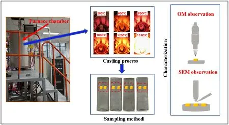
Fig.1.The casting process and and microstructure observation strategy of the directionally solidified nickel-based superalloy.
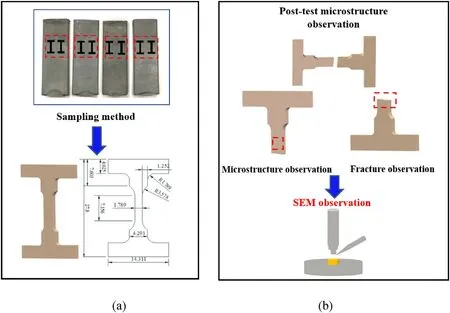
Fig.2.The geometry size (a) and post-test microstructure observation strategy (b) of the specimen (Unit: mm).
Measurement and calculation of the primary dendrite arm spacings(PDAS)λ1and secondary dendrite arm spacings(SDAS)λ2by equations(1) and(2)[27,28]:
where A is the area of the view field, N is the number of primary dendrites in the field, L is the length of the primary dendrite core in the selected region,and n is the number of secondary dendrites on the length of L.
The changes of primary dendrite spacing and secondary dendrite spacing of DZ125L alloy at different withdrawal rates are shown in Fig.4.The PDAS with the withdrawal rates of 4 mm/min, 6 mm/min, 8 mm/min, 9 mm/min are 357 μm, 321 μm, 315 μm, 329 μm, and the SDAS correspond to 63 μm、59 μm、46 μm、43 μm.The values of dendrite spacing both gradually decrease with an increase in the withdrawal rate.
Hunt [29] proposed the relation of PDAS, the thermal gradient (GL)and the growth rate of the crystal(R):
When the facilities,the shell material and the moulds are determined,the thermal gradient of the test bars same section can be assumed constant.With the increase in withdrawal rate,the increase of R value leads to the decrease of GL-0.5R-0.25, resulting in the decrease of primary dendrite spacing.Similar effects can be obtained on secondary dendrites.Some studies[30-32]have been conducted on the relation between SDAS and process parameters.The results indicated that SDAS and growth rate still follow the exponential law.Closely packed and well-distributed dendrite microstructure can be achieved by determining the appropriate withdrawal rate.
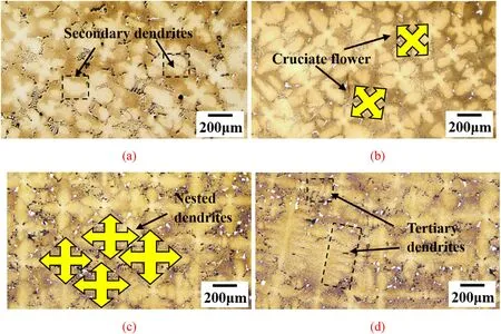
Fig.3.Dendrite morphology at different withdrawal rates: (a) 4 mm/min, (b) 6 mm/min, (c) 8 mm/min, and (d) 9 mm/min.
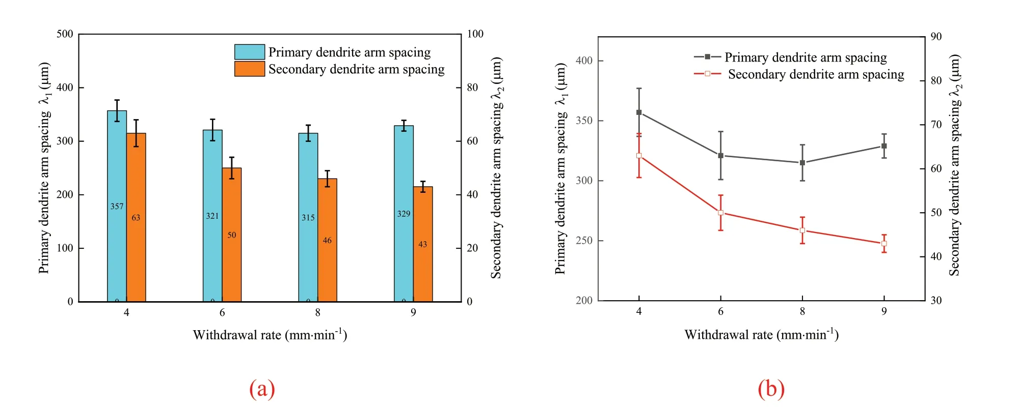
Fig.4.Comparison (a) and changing trend (b) of primary and secondary dendrite spacing under different withdrawal rates.
3.2.Effect of withdrawal rate on the γ′ phase
The γ′phase is a major strengthening phase in DZ125L alloy, which coherently precipitates from the γ matrix during the cooling process.The nucleation number and growth period of γ′phase have essential effects on final morphology.According to the classical nucleation theory, the critical nucleation entropy of γ′phase precipitated from the matrix is as follows [33]:
where ΔG is the critical nucleation energy,ΔGvis the change in volume free energy per unit volume,ΔGSis the change in surface free energy per unit volume,σ is the specific surface energy of the γ and γ′phases.It is well known that the lower withdrawal rate leads to the lower supersaturation and undercooling of the solute,resulting in the smaller ΔGvand larger ΔG.Due to the low nucleation, γ′phase has enough time to develop.An incremental withdrawal rate results in an increasing degree of undercooling,which promotes the nucleation rate of the γ′phase.As a consequence,the irregular morphology of γ′phase is found with deficient diffusion of elements caused by a reduction in the sufficient growth time of γ′phase.The γ′phase morphologies of DZ125L as-cast alloy at low and high withdrawal rates are shown in Fig.5.The irregular morphology of the γ′phase is probably caused by the uneven nucleation of the γ′phase during the cooling process.In the low nucleation rate region,γ′phase size easily reaches the critical size.As a result, these γ′phase deforms to stabilize the whole system,resulting in γ′phases depression.

Fig.5.The γ′ phase microstructure of DZ125L as-cast alloy at (a)4 mm/min and (b)8 mm/min.
In order to obtain the desirable microstructure,proper heat treatment is necessary to homogenize the elemental distribution and fully precipitate γ′phase.Fig.6 plots the relation between the γ′phase size and withdrawal rate in different regions after heat treatment.The results reveal that the γ′phase size in the dendrite core and interdendritic region decreases with increasing withdrawal rate.In addition,the size of the γ′phase in the dendrite core is smaller than that in the interdendritic region.
Fig.7 presents the γ′phase microstructure in the dendrite core and interdendritic region formed at different withdrawal rates.With the increase of withdrawal rate,the γ′phase gradually changes from disorderly morphology to regular cube in both dendrites and interdendritic region,but γ′phase in the interdendritic region is rougher than that in dendrites.The degree of the supersaturation is increased because of the enriched γ′phases forming element in the interdendritic region, which further enhances the growth kinetics of the γ′phase.Therefore,it is observed that the size of the γ′phase in the interdendritic region is larger than that in the dendrite core.
3.3.Effect of withdrawal rate on the carbides
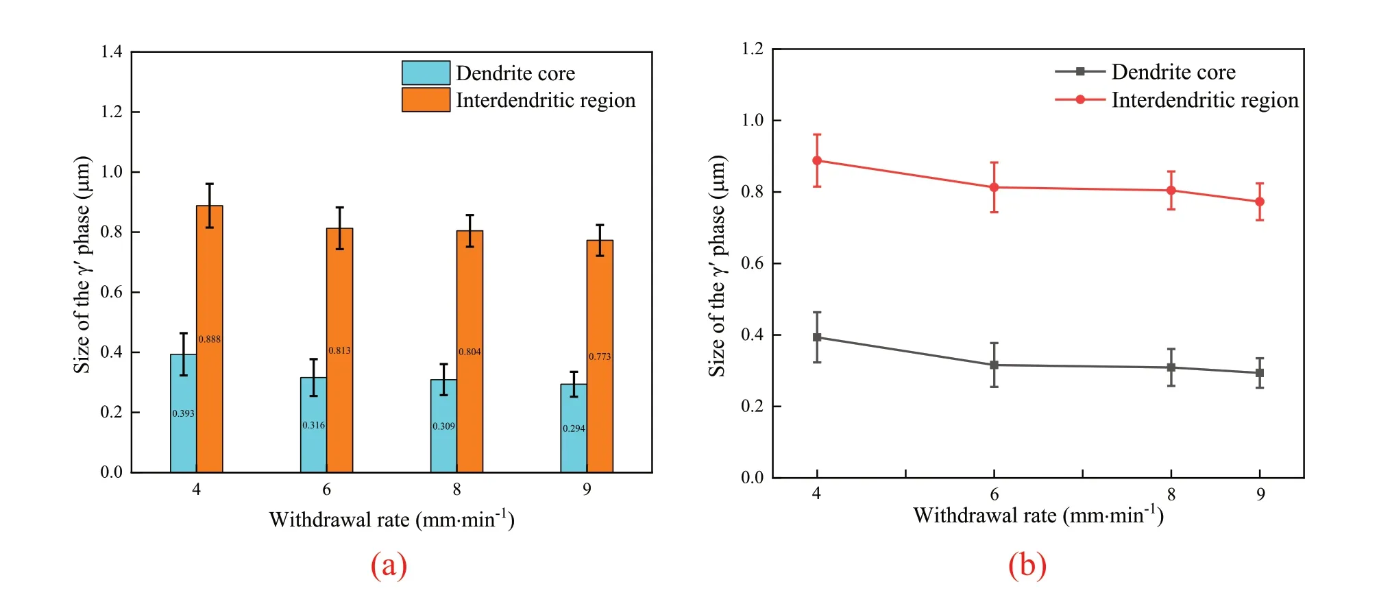
Fig.6.Comparison (a) and changing trend (b) of the γ′ phases size in the dendrite core and interdendritic region under different withdrawal rates.
The carbide is the important constituent phase precipitated during solidification in nickel-based superalloys.Based on the dynamic principle of crystal growth, the formation of carbides requires a sufficient degree of solute supersaturation, which provides a driving force for the growth of carbides.Therefore, the diffusion of the carbide-forming elements is considered a critical factor in determining the final carbide morphology.In general, octahedral blocky carbides are prone to precipitate under nearequilibrium growth, gradually transforming to the Chinese script-shaped morphology with an increasing withdrawal rate [34,35].The morphologies of carbides at different withdrawal rates are shown in Fig.8.With an increase in the withdrawal rate, the morphologies of the carbides are transformed from a blocky structure to a fine Chinese script-shaped structure.Moreover, the composition of these carbides is also be measured,which is shown in Table 2.It indicates that the carbides are primarily rich in Ta and comprise only a small amount of W and Mo can be recognized as a MC-type carbide.Under the withdrawal rates of 6 mm/min and 8 mm/min,the microstructure exhibits rod-like carbides which have longer and more complex boundaries.In this case, crack has to pass through the carbide rather than the boundaries,so the mechanical property can be improved by the barrier effect of rod-like carbides[36].The effect of withdrawal rate on carbide size is shown in Fig.9.Fig.9(a) illustrates the area fraction and width of the carbides at different withdrawal rates.The area fractions of the carbides with the withdrawal rates of 4 mm/min,6 mm/min,8 mm/min,9 mm/min are 4.5%, 4.9%, 5.73%, 5.67%.With the enhancement of the withdrawal rate,the dendrites also increase,which can effectively suppress elemental diffusion and promote elemental segregation.Enriching carbide-forming element increases the driving force of diffusion to the growth surface,resulting in the augment area fraction of carbides between dendrites.The reduction of carbide size occurs when the withdrawal rate increases.The width of the carbides,marked by red arrows in Fig.9(b)and(c),decreases from 120 μm to 33 μm when the withdrawal rates augment from 4 mm/min to 8 mm/min.It can be attributed to the increase in the withdrawal rate to promote dendrites from a loose to a dense arrangement,resulting in a reduction of carbide growth space.
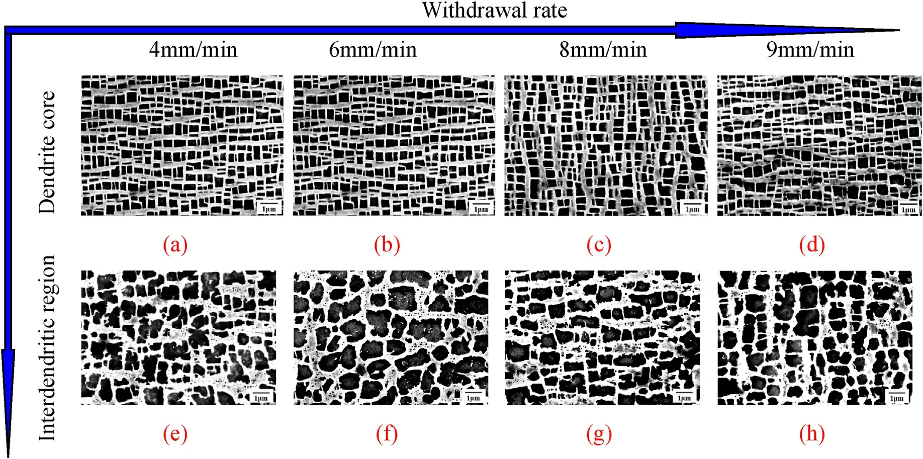
Fig.7.The morphologies of the γ′ phases in the dendritic core(a-d),and interdendritic region(e-h)at various withdrawal rates.4 mm/min(a)and(e);6 mm/min(b)and (f); 8 mm/min (c) and (g); 9 mm/min (d) and (h).
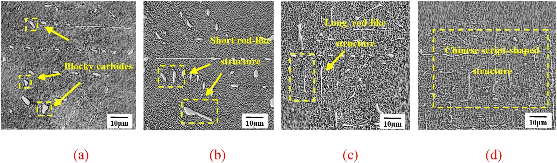
Fig.8.Carbides morphology at different withdrawal rates: (a) 4 mm/min, (b) 6 mm/min, (c) 8 mm/min, and (d) 9 mm/min.

Table 2 Compositions of MC-type carbide as measured by SEM-EDS (Wt%).
3.4.Effect of withdrawal rate on the eutectic structure
It is well known that γ/γ′eutectics can degrade mechanical properties by acting as crack initiation sites, thus leading to the alloy fracture.During the solidification process of the alloy, the growth of dendrites usually leads to the residual liquid in the interdendritic region.When the concentration of the eutectic forming element exceeds the saturation level, a fine kinetic condition for the γ/γ′eutectics nucleation will be created.The morphologies of γ/γ′eutectics at different withdrawal rates are shown in Fig.10.It can be observed that the γ/γ′eutectics at low withdrawal rates exhibit a large blocky shape,whereas a strip-like shape at high withdrawal rates.Fig.11 illustrates the area fraction of the γ/γ′eutectics at different withdrawal rates.The area fractions of the γ/γ′eutectics with the withdrawal rates of 4 mm/min,6 mm/min,8 mm/min,9 mm/min are 0.76%, 0.59%, 0.83% and 0.98%.The figure indicates that the area fraction of the γ/γ′eutectics decreases first and then increases with an increasing withdrawal rate.This result is mightily related to the element diffusion in the interdendritic region.Diffusion distance and diffusion time greatly affect element diffusion.At the low withdrawal rate, the increasing interdendritic microsegregation due to the considerable diffusion distance is the principal reason for the high area fraction [37].The high withdrawal rate leads to a greater effect on the diffusion time in the element diffusion,resulting in the aggravation of the microsegregation degree.Therefore, the formation of the γ/γ′eutectics also increases at a high withdrawal rate.When the diffusion time and diffusion distance are mutually constrained, the degree of microsegregation reaches a relatively low level,effectively decreasing the area fraction of the γ/γ′eutectics.When the withdrawal rate increases from 4 mm/min to 6 mm/min, the area fraction of eutectics tend to decrease,which can effectively improve the mechanical properties of the alloy.Subsequently, as the withdrawal rate increases, the area fraction of eutectic increases slightly,but the size has significantly decreased.When the withdrawal rate is 9 mm/min, more strip-like eutectics can be observed, and the size slightly increases.The comprehensive effect of eutectic size and area fraction determines alloy properties [38-40].Actually, carbides [20] precede γ/γ′eutectics formation in the solidification process.The formation of carbides occupies the nucleation sites of γ/γ′eutectics and reduces the concentration of the eutectic forming element in the residual liquid, which retards the precipitation of γ/γ′eutectics.It can be seen that the area fraction of the γ/γ′eutectics changes gently.
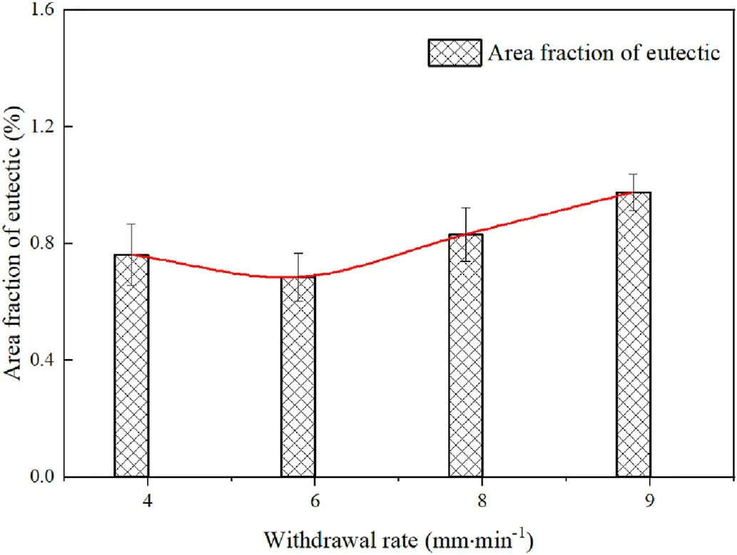
Fig.11.The change of γ/γ′ eutectics area fraction at different withdrawal rates.

Fig.10.The γ/γ′ eutectic morphology at different withdrawal rates: (a) 4 mm/min, (b) 6 mm/min, (c) 8 mm/min, and (d) 9 mm/min.
3.5.Effect of withdrawal rate on the creep properties
3.5.1.Experimental results
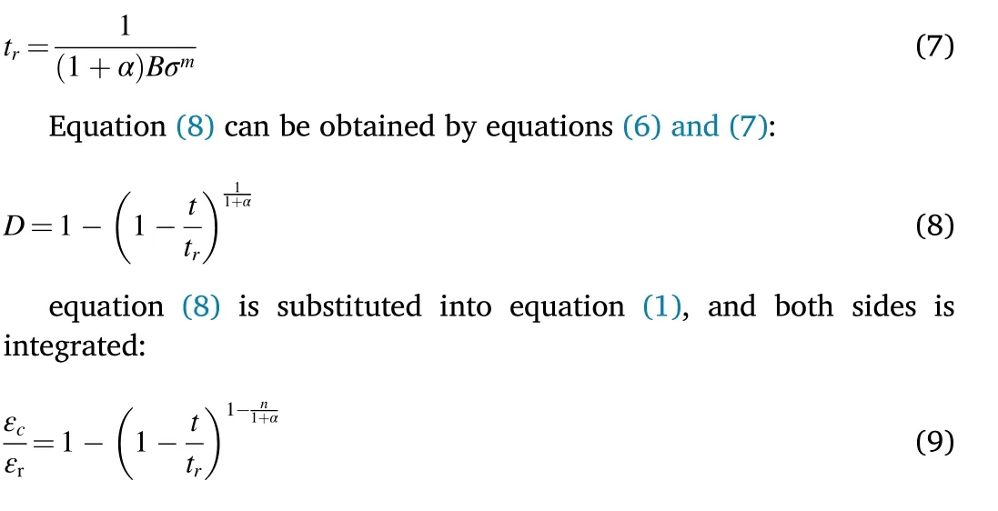
The effect of withdrawal rate on the creep behavior of the directionally solidified nickel-based superalloy at 980°C/243 MPa is shown in Fig.12.As can be seen from the figure,the creep curves are exponential,with no apparent primary creep stage but rather a steady-state creep stage and an accelerated creep stage.The creep lives with the withdrawal rates of 4 mm/min,6 mm/min,8 mm/min,9 mm/min are 30.1 h,42.2 h,43.4 h and 31.7 h.The creep rupture life increases first and then decreases with the increasing withdrawal rate.There is no significant difference in creep life at 6 mm/min and 8 mm/min,while the specimens at 4 mm/min and 6 mm/min are prone to failure.It proves that the withdrawal rate significantly affects the creep failure of the directionally solidified nickel-based superalloy.At the same time, the steady-state creep rate increases and quickly enters the accelerated creep stage.The lower creep rate helps to increase resistance to creep, so the higher or lower the withdrawal rate,the shorter the creep fracture life.
The creep fracture surface and the longitudinal section SEM micrographs at different withdrawal rates are shown in Fig.13.Fig.13(a-d)illustrates different square cleavage planes and dimples on the fracture surfaces at different withdrawal rates.The lower the withdrawal rate,the worse the heat sinking capability of the alloy.The uneven microstructure leads to loose material,which is prone to crack and failure under external loading.The specimen fracture surface at 4 mm/min shows the characteristics of quasi cleavage fracture, as shown in Fig.13(a).Square cleavage planes are densely distributed on the fracture, and some cleavage planes are connected to form dimples.The fracture surface becomes less flat, mainly showing step-like tears.When the withdrawal rate is 6 mm/min,the dimples are slightly larger and increase in number than before.The main fractographic appearances are dimple-cleavage mixed fracture phenomena.The mechanical properties are obviously improved with an increased withdrawal rate and sufficient cooling.The specimen fracture surface at 8 mm/min has a few larger dimples in the center and some micro-voids in the center of the dimple.The area proportion decreases of the micro-cleavage surface.Fracture observation indicates that the specimen ruptured in a ductile manner.The fracture specimen at 9 mm/min clearly exhibits the necking phenomenon and severe damage by the applied stress.There are larger and deeper dimples and some small cleavage planes in the interior,basically showing mixed fracture.
Fig.13(e-h) shows the micrographs of the longitudinal section at different withdrawal rates.During the rafting process,γ′phase connects with each other to form the rafting structure.At the same time, the γ matrix parallel to the external loading will narrow down and gradually disappear, which results in a γ structure perpendicular to the external loading.With the increased withdrawal rate,the rafting channel of the γ′phase gradually changes from discrete to continuous, which tends to develop into thin strips.Significantly coarser rafting structure and wider matrix channel appear in the creep process of the lower or higher withdrawal rate.It is generally believed that wider matrix channels are more likely to deform.The more regular the rafting,the larger the aspect ratio of the γ′phase, which can effectively inhibit the generation of the dislocation climbing mechanism [41], forcing dislocation extension mainly through the mechanism of shearing the γ′phase,then increasing the energy required for dislocation expansion.So mechanical properties of the alloy are improved.
Surface examination of the longitudinal section reveals the presence of some microcracks perpendicular to the direction of external loading.The microcracks of 4 mm/min and 9 mm/min are significantly more than those of 6 mm/min and 8 mm/min.The crack size is also significantly larger than that at the moderate withdrawal rate.As shown in Fig.14,it can be observed that there are obviously larger and deeper cracks in the fracture with a withdrawal rate of 4 mm/min.In addition,the porosities generated by casting or creep tests are important regions for crack nucleation.Fig.15(a)shows the detailed local appearance of microcracks near the fracture.It can be clearly seen that the cracks inner is smooth and circular,accompanied by an obvious crack tip outside.The presence of residual eutectic structure and carbides also significantly impacts alloy thermal durability (Fig.15(b)).The initiation of cracks in this region is because the eutectics easily separate from the matrix under the external loading,which is caused by the different thermal expansion coefficients from the matrix.Therefore, creep cracks are easy to initiate in the interdendritic region containing eutectics, carbides and porosities.Subsequently,the microcracks and porosities start to elongate and link up to each other,increasing the stress in the remaining undamaged surface and leading to rupture.
3.5.2.Creep-damage constitutive model
As discussed above,adjusting the withdrawal rate during casting is a crucial method to optimize microstructure and eventually obtain improved mechanical properties.An increased withdrawal rate refines the dendritic structure and reduces the size of the γ′phase, effectively enhancing the creep life [42-45].Meanwhile, the rod-like MC carbides and fine strip-like eutectics occur in alloys of the moderate withdrawal rates, significantly strengthening the mechanical properties.The final mechanical properties of the alloy are determined by the comprehensive effect of various microstructure characteristics, showing the creep life trend of first increasing and then decreasing.
Considering the manufacture and safe operation of aero-engines,establishing the quantitative relation between casting parameters and creep behavior is an important reference for developing a higher performance nickel-based superalloy.Modeling of damage processes under various creep conditions has been developed to predict the high temperature creep lives of alloys [46-48].The phenomenological model,proposed by Kachanov [22] and Robotnov [23], has been widely accepted and used to evaluate creep lives.The creep-damage constitutive equation can be written as follows:
Where εcis the creep strain rate and σ is the stress.D is the damage variable which can be changed from 0 for an initial state(undamage)to 1 at final state (completely ruptured).A, n, B, m and α are material constants which can be determined from creep rupture strain data.
By integrating equation(6)over the damage limits of 0-1:
Where εcis the creep strain,εris the creep rupture strain, t is the creep time and tris the creep rupture time.
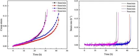
Fig.12.(a) Creep strain (b) and strain rate curves of the directionally solidified nickel-based superalloy at 980 °C/243 MPa.
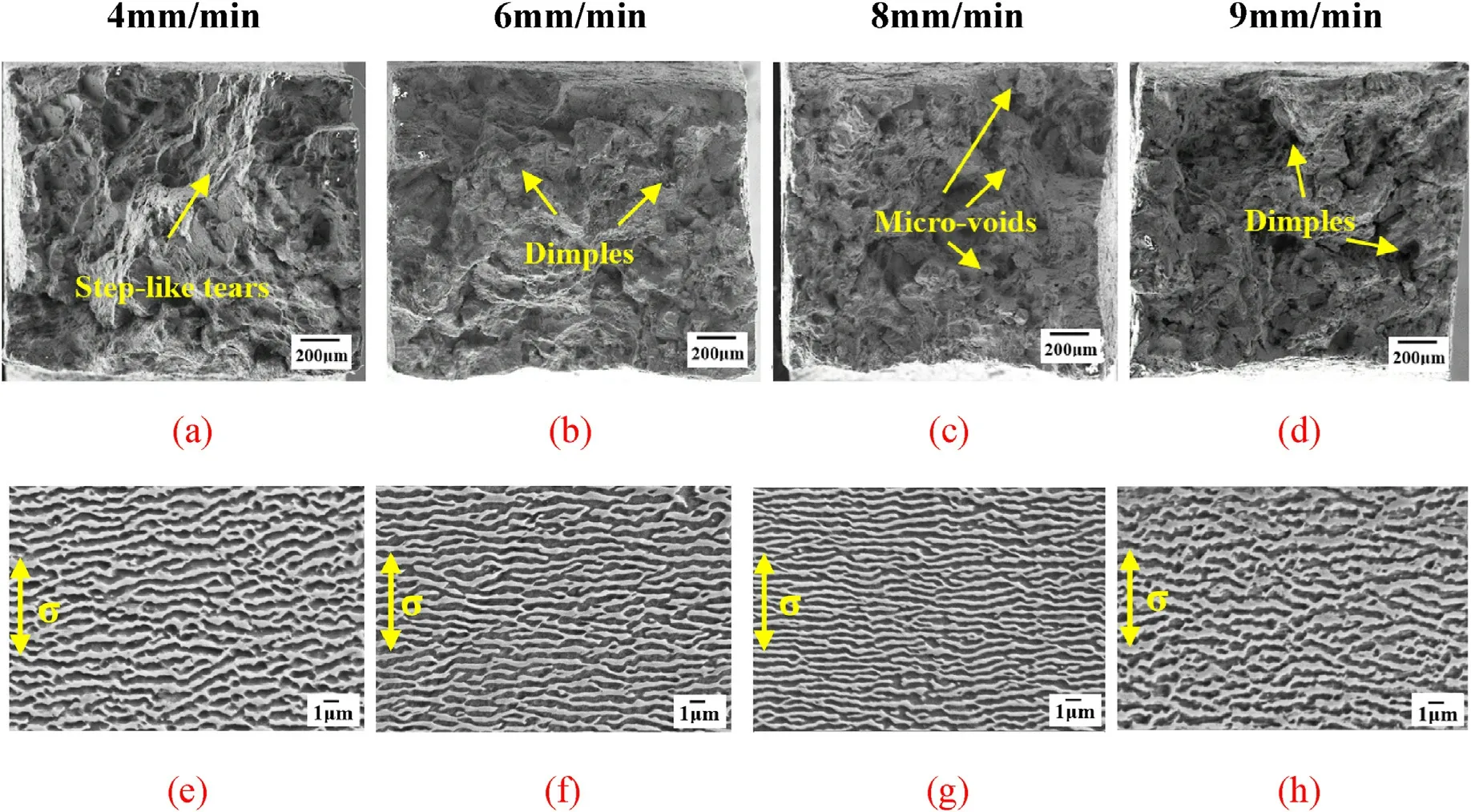
Fig.13.The creep fracture surfaces (a-d) and the γ ′phase microstructure of longitudinal section (e-h) at different withdrawal rates.
Fig.14.The microcrack morphology of the longitudinal section at different withdrawal rates: (a) 4 mm/min, (b) 6 mm/min.
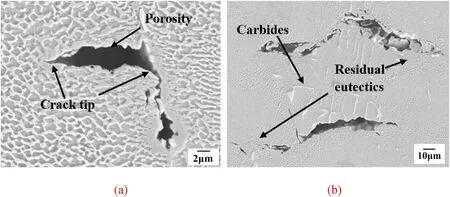
Fig.15.The detailed local appearance of microcracks near (a) the fracture and (b)the eutectics and carbides.
The continuum damage mechanics approach involving Eqs.(5)-(9)has been incorporated within the subroutine of ABAQUS.A suitable creep model was established based on working conditions, and creep mechanical parameters at different withdrawal rates were assigned to the model.The relation between withdrawal rate, creep constitutive parameters and creep life can be obtained.The effect of the withdrawal rate on the creep parameter m in the creep model is shown in Fig.16(a).With the increase of the withdrawal rate, the value of m decreases first and then increases.The relation between the withdrawal rate and creep parameters can be extended to predict the creep life of directionally solidified nickel-based superalloys under other conditions.
In order to demonstrate the effect of the withdrawal rate, the creep damage was analyzed through the parameter optimization and finite element simulation.It can be seen from Fig.16(b) that creep damage develops to complete rupture rapidly after a drastic increase in the accelerated creep stage.In all,the damage evolution of 4 mm/min and 9 mm/min is significantly faster.In the early stage,the creep damage of 4 mm/min and 9 mm/min is slightly more extensive than that of 6 mm/min and 8 mm/min.The creep damage is about 6.24 × 10⁻³at 4 mm/min and 4.43 × 10⁻³at 6 mm/min.The difference between the two gradually increases under the same creep moment.In the middle of creep,the creep damage is about 2.32×10⁻¹at 4 mm/min and 1.43×10⁻¹at 6 mm/min.The above discussions indicate that microcracks are prone to initiate in the microstructure defects caused by low and high withdrawal rates,and a proper amount of holes and microcracks are also formed during the creep process.The simulation results are consistent well with the tests.
Fig.17 and Table 3 show the comparison of creep test and simulation results at 980°C/243 MPa under different withdrawal rates.The K-R model captures the overall creep behavior reasonably well.As can be seen from the figures, the creep curves with withdrawal rates of 6 mm/min and 8 mm/min have a obvious steady-state creep stage and an accelerated creep stage.With the increase or decrease of the withdrawal rate, the creep deformation rate at 4 mm/min and 9 mm/min increases rapidly,resulting in a significant decrease in the steady-state creep time,and the final creep lives decrease to about 30 h.
The creep life calculated by the K-R damage model are basically consistent with the experimental results, as shown in Table 3, proving that the model has high accuracy.The relation between casting parameters and creep mechanical properties of directional solidification alloys is established by this model, which can be extended to reveal creep mechanism and life prediction under other casting process parameters.
4.Conclusions
The effect of the withdrawal rate on the microstructure and creep behavior of a directionally solidified nickel-based superalloy DZ125L was investigated by a combination of test observation and finite element simulation.Based on the obtained results,the following conclusions can be formulated.
(1) An increased withdrawal rate refines the dendritic structure and reduces the size of the γ′phase, transforms the MC-type carbides from the blocky structure to the Chinese script-shaped structure,and decreases the size of the eutectic structures.The final mechanical properties of the alloy are determined by the comprehensive effect of various microstructure characteristics.
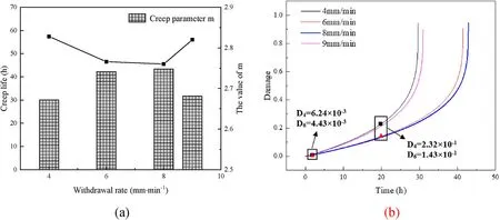
Fig.16.The changes of the (a) creep parameter m (b) damage with different withdrawal rates.
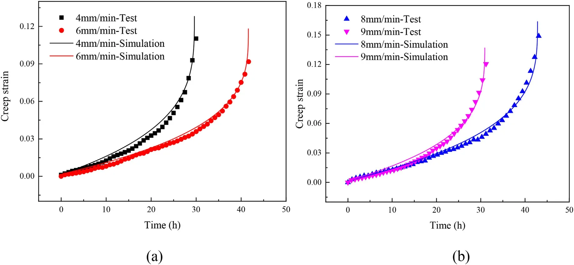
Fig.17.Comparison of creep test and simulation results at 980 °C/243 MPa under different withdrawal rates: (a) 4 mm/min and 6 mm/min (b) 8 mm/min and 9 mm/min.
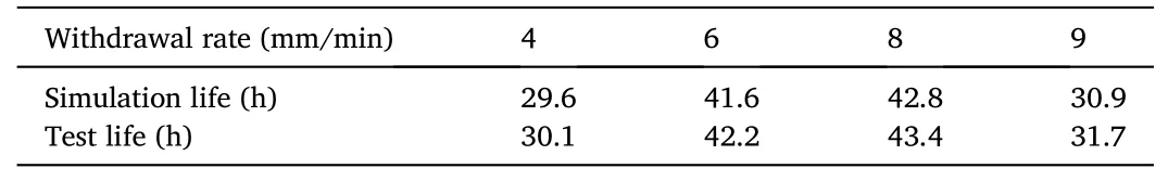
Table 3 Creep rupture life of test and simulation at different withdrawal rates.
(2) With the increase of the withdrawal rate, the creep rupture life first increases and then decreases.The specimens at 4 mm/min and 6 mm/min show the dimple-cleavage mixed fracture mechanism.Fracture examination reveals that the smaller and fewer cracks after creep tests occur in the specimen at these two rates.The alloy with moderate withdrawal rates exhibits enhanced creep rupture life.
(3) The quantitative influence of the withdrawal rate on the creep life was estimated using the K-R creep damage model.Creep damage rapidly increases at the low or high withdrawal rates,resulting in a significant decrease in the creep life.The creep curves calculated by the K-R model are basically consistent with the experimental results, proving that the model has high accuracy.
Declaration of competing interest
We would like to submit the enclosed manuscript entitled “Effect of the withdrawal rate on the microstructure and creep behavior of the directionally solidified nickel-based superalloy”, which we wish to be considered for publication in “Progress in Natural Science: Materials International”.No conflict of interest exits in the submission of this manuscript,and manuscript is approved by all authors for publication.I would like to declare on behalf of my co-authors that the work described was original research that has not been published previously, and not under consideration for publication elsewhere, in whole or in part.All the authors listed have approved the manuscript that is enclosed.
Acknowledgement
This research was funded by the National Natural Science Foundation of China(51875461),the National Science and Technology Major Project(2017-IV-0003-0040,J2019-IV-0011-0079).
 Progress in Natural Science:Materials International2023年3期
- Progress in Natural Science:Materials International的其它文章
- Research progress of composite cathode materials for Solid oxide fuel cells
- A review on solidification of alloys under hypergravity
- Improving mechanical properties of Mg-Sn alloys by co-addition of Li and Al
- Multi-stimuli bilayer hydrogel actuator for remotely controllable transportation of droplets
- The formation and temperature stability of microemulsion emulsified by polyoxyethylene ether surfactant
- Towards high-efficiency of hydrogen purification in metal hydride