
Flight control of a flying wing aircraft based on circulation control using synthetic jet actuators
2023-11-10 02:15ZhijieZHAOXiongDENGZhenbingLUOWenqiangPENGJianyuanZHANGJiefuLIU
CHINESE JOURNAL OF AERONAUTICS 2023年10期
Zhijie ZHAO, Xiong DENG, Zhenbing LUO, Wenqiang PENG,Jianyuan ZHANG, Jiefu LIU
College of Aeronautics and Astronautics, National University of Defense Technology, Changsha 410073, China
KEYWORDS
Abstract To achieve the nice stealth performance and aerodynamic maneuverability of a Flying Wing Aircraft(FWA),a longitudinal aerodynamic control technology based on circulation control using trailing-edge synthetic jet actuators was proposed without the movement of rudders.Effects on the longitudinal aerodynamic characteristics of a small-sweep FWA were investigated.Then,flight tests were carried out to verify the control abilities, providing a novel technology for the design of a future rudderless FWA.Results show that synthetic jets could narrow the dead zone area, improve the flow velocity near the trailing edge, and then move the trailing-edge separation point and the leading-edge stagnation point downwards,which make the effective Attack of Angle(AOA) increase, thereby enhancing the pressure envelope area.Circulation control based on synthetic jets could improve the lift, drag and nose-down moment.The variations of lift and nosedown moment decrease with the growth of AOA caused by the improved reverse pressure gradient and the weakened circulation control efficiency.Finally,synthetic jet actuators were integrated into the trailing edge of a small-sweep FWA, which could realize the roll and pitch control without deflections of rudders during the cruise stage, and the maximum roll and pitch angular velocity are 12.64 (°)/s and 8.51 (°)/s, respectively.
1.Introduction
Flying wing aircraft, eliminating horizontal tails and vertical tails, markedly cut down adverse aerodynamic interference and radar cross sections, which have great significance for the future aircraft design.1Tailless layouts, however, display insufficient heading stabilities and poor longitudinal control abilities, presenting extremely high design demands for the flight control system based on mechanical rudders.2Rudders,with disadvantages of complex mechanical structures, large volume and weight, and insufficient control abilities at low speed,could also destroy the nice stealth performances of Flying Wing Aircrafts (FWAs).3Active flow control actuators may replace mechanical rudders to become the nextgeneration flight control effectors.Active Flow Control(AFC), with advantages of no need for rudders, high efficiency, adjustable momentum and being easily integrated,has been applied in Circulation Control(CC)4,5and thrust vectoring control,6,7exhibiting dramatic engineering significance for the next-generation aircraft.
Circulation control,an extremely critical flight control technology, is considered as one of the most promising flight control methods.8Until now,flight control technology realized by CC has been verified on DEMON,9MEGMA,10FWAs without rudders,11aircraft controlled by zero-mass-flux dual synthetic jet actuators12and so on.Traditional CC, however,generally runs by inducing a large amount of gas from engines and carrying an air bottle or fans, which discount the net thrust and payloads and consume a quantity of energy, such as ICE-04, the perfect profile, where the weight and volume of AFC module are 176 kg and 121.5 dm3, respectively.13Significantly, nozzles, ducts and valves account for a large proportion, and enhance the complexity of system integration.Therefore, there is an urgent need for a new-generation circulation control actuator with characteristics of light weight,compact structures, low energy consumption, ease of integration, and convenience to adjust.
Synthetic Jet Actuators (SJAs),14with the advantages of fast response, low energy consumption, compact structure,lightness,no need of gas sources or pipelines,and easily being integrated, have shown great application potentials in flight control.15,16Zhang et al.17suggested that ΔCL/Cμof Synthetic Jets (SJs) is one order of magnitude higher than that of steady blowing,where Δ means difference,CLis lift coefficient, Cμis momentum coefficient.The blowing and sucking phases are both capable of delaying the Trailing-Edge (TE)separation,and improving the circulation and the lift.The lift pulsation, however, will be enlarged using low-frequency actuations (F+~O(1)), which is not conductive to the flight control system.Meanwhile, Glezer et al.18present that high-frequency actuations (F+~O(10)) do not rely on coupling to a global instability, but could form a small quasisteady flow interaction domain adjacent to the surface that displaces the local streamlines sufficiently to modify the local pressure distribution, which have emerged higher control abilities than low-frequency actuations and decoupled aerodynamic force from time.Moreover, SJs could modulate the vortex structures of ‘‘dead zones” near the trailing edge,change the Kutta condition and the pressure distribution,and then generate stable control force and moment for aircraft.19Luo et al.invented a dual synthetic jet actuator,20which improves the energy efficiency and solves the problem of vibrating diaphragm failures, and integrated it into an Unmanned Aerial Vehicle (UAV), showing the nice threeaxis attitude control ability.12,21
To explore the application potential of SJAs in circulation control of FWAs, SJAs are integrated into a small-sweep FWA.Aerodynamic control characteristics and mechanism are analyzed by numerical simulations.Furthermore, SJAs are installed in an in-house FWA with a small sweep angle to demonstrate the flight control features.
2.Physical model and numerical method
An in-house half FWA,with a span b1of 1.816 m,an aerodynamic chord c1of 0.2946 m,a sweep angle of 26°and the wing area of 0.535 m2,is chosen as the control objective,exhibited in Fig.1(a).Thirty-two SJAs are located along the trailing edge,half of which are near the upper surface, while the others are close to the lower surface.The first SJA,with the distance from the symmetry surface of 34.7% b1, is placed in the wing section,and the others are evenly arranged in the spanwise direction,which have the identical spanwise lengths of 2.6%b1and the same distance of 1.2%b1between each other,as displayed in Fig.1(b), where red lines represent SJAs.The SJAs’ exits,perpendicular to the trailing edge, are tangent to the Coanda surface.The height of exits h1and the radius of rounded surfaces r1are chosen as 0.247% c and 2.29% c, respectively,where c means the chord of a local section, as shown in Fig.1(c).In numerical calculations, Mach number is set as 0.1, and Reynolds number based on c1is 674119.
The finite volume method is applied to discretize the threedimensional compressible unsteady Reynolds-averaged Navier-Stokes equations, and a density-based solver is used to solve it.Shear stress transport k-ω model is selected as the turbulent model.Roe flux differential splitting scheme is used to discretize the spatial term, the convection term is a secondorder upwind scheme, and the time-discrete scheme is a firstorder implicit scheme.Moreover, the convergence criterion,the residual error is less than 10-5, is set.In unsteady calculations,the time step is selected as 1/80 of the SJA driving cycle,the maximum number of iterations per time step is set as 40,and a total of 200 flow control cycles are calculated to ensure the convergence of results.In addition, time-average aerodynamic force and moment, considering the comprehensive effects of SJ reaction force and force on the solid surface,5are calculated based on 10 flow control cycles.
The three-dimensional structured O-H grid is chosen for calculations, and computational domains and surface grids are shown in Fig.2.Grids are encrypted on the wing surface,outlets of SJAs,leading edges,and trailing edges,respectively.The height of the first layer y+is approximately equal to 1.In addition,the upstream and downstream streamwise lengths of computational domains are both 40c1.The upward and downward normal lengths of computational domains are both 30c1.The spanwise length is set as 30c1.No-slip wall conditions are applied to the surfaces of aircraft and SJAs.Outer boundary is set as the pressure far-field condition.An array of SJAs is placed along the trailing edge, and the local mesh is shown in Fig.2(a).For convenience, the internal structures of SJAs are omitted in calculations, and only SJA inlets, shown in Fig.1(c) (red lines), are kept to simulate the SJA, and then a periodically fluctuating pressure inlet condition is utilized on the inlet of SJAs to generate SJs.It is noteworthy that SJAs close to the trailing edge of the suction surface will only be actuated for exploring its flow control mechanism.
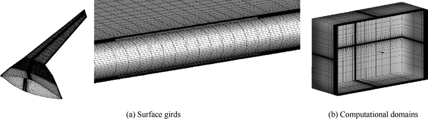
Fig.2 Computational mesh of FWA.
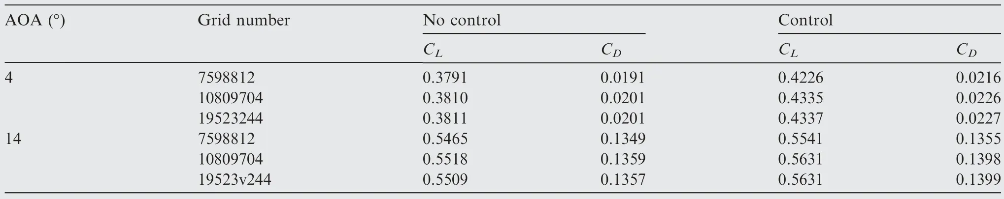
Table 1 Grid independence verifications.
Grid independence verifications before and after control at classical Attack of Angles(AOAs)are carried out,as shown in Table 1, which support that the lift coefficient CLand drag coefficient CDwill keep constant when the grid number exceeds 10809704.Therefore, the final grid number is set as 10809704.Moreover,numerical verifications are implemented.An in-house wing with a sweep angle of 5° at Re = 250000 is selected and relative comparison is shown in Fig.3(a).Meanwhile, a classical circulation airfoil CC-E0020EJ with momentum corfficient Cμ=0.047,freestream Mach number Ma∞=0.10049, and Re = 48800022is also tested and pressure distributions are shown in Fig.3(b),where Cpis pressure coefficient.Table 1 and Fig.3 demonstrate that this method could predict the flow fields of FWAs with or without control of TE SJAs well.
The key control parameters contain dimensionless frequency F+and momentum coefficient Cμ,which are described as
where U∞, Umax, f, Ai, K, S are the freestream velocity, the peak velocity of SJs, the driving frequency of SJAs, the area of SJA’s outlet,the number of SJAs and the wing area,respectively.F+and Cμare separately chosen as 4.24 and 0.0019.It is worthy to note that the difference of peak velocities at each SJA outlet is less than 1.45 m/s.In fact, these parameters are all chosen based on practical engineering experience and real design parameters of SJAs.In addition, our previous studies have shown the driving frequency of SJAs has little effects on pressure distributions and aerodynamic characteristics, so F+is chosen merely based on our engineering experience.
3.Aerodynamic force characteristics
CL, CD, pitching moment coefficient Cm, lift-drag ratio L/D and their variations before and after control at AOAs from 0°to 18°are displayed in Fig.4.The center of gravity is placed at 403 mm from the leading edge.

Fig.3 Numerical method verifications.
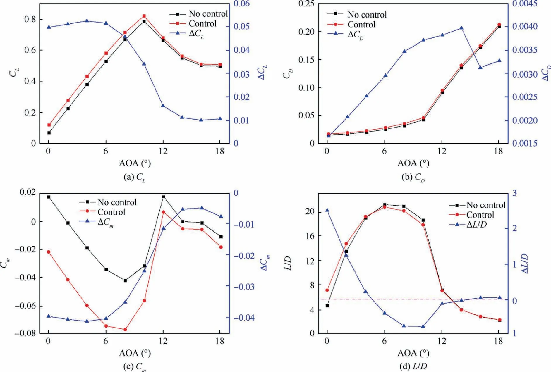
Fig.4 Aerodynamic force/moment before and after control.
After control, CLincreases obviously before stalling,while CLincrement decreases gradually with the augmentation of AOAs.Meanwhile,CDexhibits a non-linear increasing trend, with the maximum CDincrement occurring at AOA of 14°.Fig.4(c) indicates that the pitching moment will be attenuated after control,namely the nose-down tendency could be generated.Moreover,Cmdecrement is great before stalling, while decreases with the growth of AOAs,similar to the trend of CL.Fig.4(d) supports that the changing process of L/D emerges three stages under the control of SJAs.In detail, L/D will be improved from 0°to 4°, while slightly decreases between 6° and 12°, and then basically keeps constant after 14°.Based on the analysis of Fig.4, TE SJAs can be qualified to control the roll and pitch attitudes at small AOAs for FWAs with a small sweep angle.
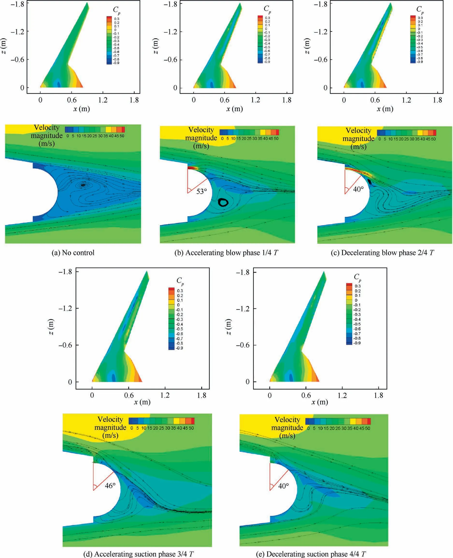
Fig.5 Upper-surface pressures and trailing-edge flow evolution before and after control (AOA of 2°).
4.Flow control mechanism
The control mechanism will be analyzed based on flow fields and pressure distributions before and after control.For this aerodynamic layout, flow fields over the wing surface after stalling are dominated by three-dimension spanwise separation.23Pressure distributions and velocity evolution over the suction surface at AOAs of 2°, 8° and 18° are carefully analyzed to illustrate the flow control mechanism of TE SJAs.
At self-trimming AOA of 2°,pressure distributions over the upper surface and TE flow field evolution at section z =–1.2 m before and after control are shown in Fig.5, where T is the driving period of SJs.The wing is dominated by attaching flow fields and separation appears from the beginning of the Coanda surface without control.After control, there is no significant change of pressures along the fuselage section,while an obvious low-pressure zone occurs at the wing section.This low-pressure area forms close to the trailing edge in the accelerating blow phase (1/4 T), evolves towards the leading edge in the decelerating blow phase (2/4 T) and the accelerating suction phase (3/4 T), and finally moves to the vicinity of the leading edge in the decelerating suction phase (4/4 T).The evolution of low-pressure zones also indicates effective AOAs gradually diminish from 1/4 T to 4/4 T.Moreover,the closer the low-pressure area is to the wing tip,the stronger this low-pressure zone is, and the better control effects could be achieved.This is because the section chord close to the wing tip is smaller, and the relative momentum coefficient is higher than that at the control position near the wing root with the same jet velocity.From the view of TE flow evolution,the area of ‘‘dead zone” is alleviated and the TE separation is significantly delayed.Meanwhile, the separation point emerges periodic fluctuations and reaches a peak of 53° in the accelerating blow phase(1/4 T),while the whole control process is still limited in the boundary layer control regime.10What is more,the flow velocity adjacent to the trailing edge is greatly enhanced,indicating the pressure dips, and hence the lift and nose-down moment are improved.It is worthy to note that periodic evolution of the vortex and separation positions also indicates periodic fluctuations of aerodynamic force and moment.17Fig.6 shows the sectional average pressure distributions at z = –1.2 m before and after control, revealing that Leading-Edge (LE) and TE suction peaks are greatly improved, the LE stagnation point has also been slightly put downwards,and then the negative pressure on the suction side and the positive pressure on the pressure side both increase, which means the pressure envelope will be effectively enlarged, and hence a rise of CLcould appear.
At AOA of 8°,pressure distributions over the upper surface and TE flow field evolution at section z = –1.2 m before and after control are shown in Fig.7.There is no obvious change of pressures and evolution of low-pressure areas over the upper surface under the control of SJAs.Pressure fluctuations also occur near the trailing edge but their influencing area is limited.Above pressure features generate the lower ΔCLthan that at AOA of 2°, with the reason that when the AOA increases, momentum of boundary layer augments, and then the valid momentum ratio reduces, weakening the CC efficiency.22TE flow evolution process resembles that at AOA of 2°.Moreover, locations of separation point and the maximum separation angle do not show significant changes compared with those at AOA of 2°.Sectional average pressure distributions at z=–1.2 m before and after control are shown in Fig.8, which also emerge the increase of LE suction and negative pressures close to the trailing edge, meaning the improvement of CL.The variation of pressure envelope, however, is lower than that at AOA of 2°, causing the lower CLincrement.
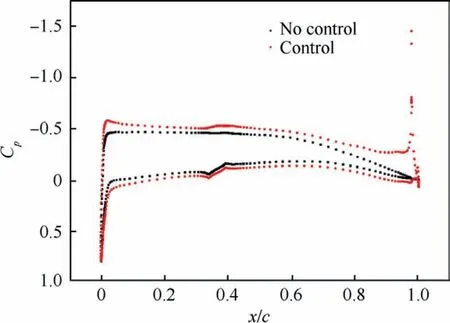
Fig.6 Sectional average pressure distributions before and after control (AOA of 2°, z = –1.2 m).
When AOA is larger than 10°, flow at the wing section is dominated by large-area separation and cases at AOA of 18°will be taken as an example to illustrate the control mechanism.At AOA of 18°,TE flow evolution at z=–1.2 m before and after control are displayed in Fig.9.TE separation point could be pushed to a farther position under the combined control of synthetic jets and separation over the upper surface compared to that at AOAs of 2° and 8°.The flow velocity is improved obviously along the Coanda surface, while does not rise ahead of the SJA outlet by entrainments.Sectional average pressure distributions at z = –1.2 m before and after control are shown in Fig.10,indicating that the pressure near the trailing edge is changed, but the pressure in other areas basically remains unchanged with the control of TE SJs.Therefore, CC efficiency and CLincrement will dip significantly when the large-area separation appears over the suction surface.
5.Flight control tests
To demonstrate the roll and pitch control ability of synthetic jets,SJAs are integrated into an in-house FWA and flight tests without the deflection of rudders during cruising are carried out.
5.1.Novel CC effectors
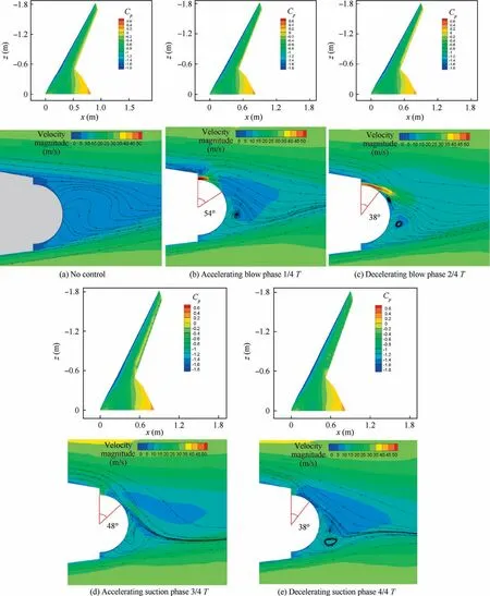
Fig.7 Upper-surface pressures and trailing-edge flow evolution before and after control (AOA of 8°).
The traditional SJA is optimized to get a higher energy level and stronger control abilities.The new generation of SJA,composed of four support plates, two shells, two exits (Exit 1 and Exit 2) and four piezoelectric diaphragms, is designed as a novel roll effector, which is shown in Fig.11(a).In fact,the CC actuator,installed along the trailing edge,is an integration of two SJAs(SJA 1 and SJA 2)with the classical structure having two PZT diaphragms,one cavity and one jet exit.Every exit is controlled by two PZT diaphragms with the opposite vibrating directions.The CC effector has two operating modes.In detail,when SJA 1(close to the wing upper surface)is actuated, this mode is called Positive Circulation Control (PCC),and when SJA 2 (close to the wing lower surface) is actuated,the mode is called Negative Circulation Control(NCC),as displayed in Fig.11(b).Four PZT diaphragms,with a diameter of 50 mm, are the same.Moreover, the length and width of CC effectors are 57 mm and 55 mm, respectively.The height of CC effectors is variable for keeping the same dimensionless parameters rf/cfand hf/cf, where rf, hf, and cfmean Coanda radius, height of SJA’s exits and chord of the local section,respectively.rf/cfand hf/cfare set as 0.0242 and 0.00226,respectively.Furthermore,the average weight of CC actuators is only 49 g, indicating great easiness to realize the integrated design.In addition, the spanwise widths of two exits are both 40 mm.In flight tests, driving frequency and alternating voltage of CC effectors are set as 710 Hz and ± 225 V, respectively.Every PZT diaphragm has the same actuated parameters,and the total power of a CC effector is 14.7 W,much less than that of traditional active flow control actuators.In addition, the peak jet velocities at 1 mm from the center of Exit 1 and Exit 2 measured by the hot wire anemometer are 80.5 m/s and 79.9 m/s,respectively,which are time-averaged values over 150 driving cycles.It is worth noting that the difference of peak velocity at exits of every CC effector is less than 1.15 m/s.
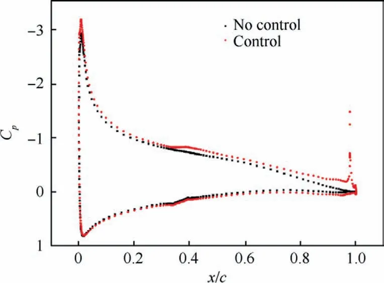
Fig.8 Sectional average pressure distributions before and after control (AOA of 8°, z = –1.2 m).
5.2.Flight platform and method
An in-house FWA platform, with characteristics of no horizontal tails, is chosen and detailed information is shown in Fig.12(a) and Table 2.Fourteen CC effectors, distributed on both sides of the wings, are installed along the trailing edge.In detail, seven effectors are installed in the left-side wing,and the others are integrated into the right-side wing.In two symmetrical wings, two CC effectors are placed close to the wing tips, and five actuators are located between ailerons and elevators, as shown in Fig.12(b),where the red parts represent CC effectors.Moreover, GoPro camera is installed in the middle of the fuselage.Aerodynamic force and moment along the wing could be modulated by the work of CC effectors,which realize the control of lateral and heading attitudes.Fig.12(c) shows the FWA body coordinates.In this experiment, roll around the Oxtis mainly focused.
The flight route is shown in Fig.13.At Point A, FWA recovers from a condition of right turn and turns into level flight before reaching Point B with the help of mechanical rudders.When reaching Point B, FWA maintains level flight and all rudders will be turned off.At Point C,CC effectors will be actuated to control the attitudes of FWA.At Point D, CC effectors will be turned off and rudders are turned on to control FWA to resume the normal flight route.The dynamic response of FWA attitudes between Point C and Point D will be focused.
5.3.Results and analyses
For verifying the roll and pitch control ability of SJAs during cursing, CC effectors installed in the right wing and the left wing are separately operated in different modes to generate asymmetrical distributions of aerodynamic force.Dimensionless F+and Cμare kept as 8.44 and 0.0013, respectively.

Fig.9 Trailing-edge flow evolution before and after control (AOA of 18°).

Fig.10 Sectional average pressure distributions before and after control (AOA of 18°, z = –1.2 m).
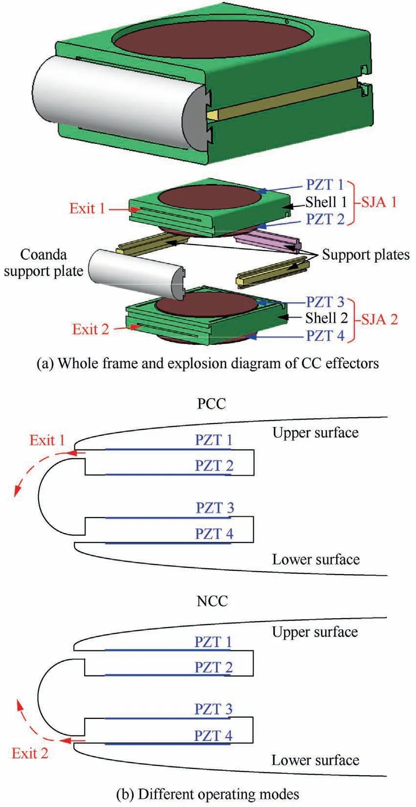
Fig.11 Structure diagram of CC effectors.
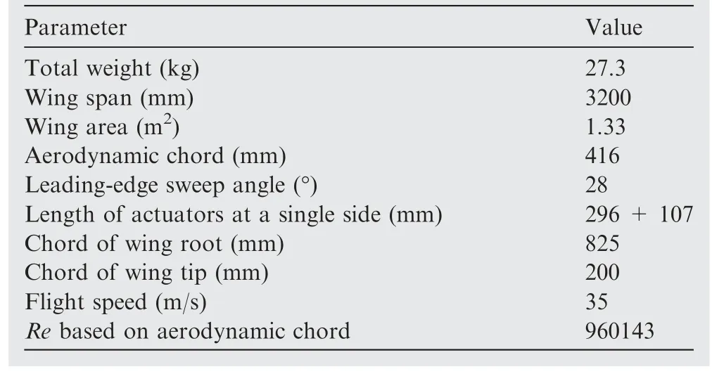
Table 2 Detailed parameters of FWA platform.

Fig.13 Flight routes.
When CC effectors of the right wing are operated in PCC modes,and CC effectors installed in the left wing are operated in NCC modes, the comparison of FWA status before and after control is displayed in Fig.14, suggesting that the FWA rolls to the left under the control of CC effectors.Lift and drag of the right-side wing increase.Meanwhile,the lift and drag of the left-side wing decrease and increase, respectively.Changes of these aerodynamic force form a leftward rolling moment,achieving the control of lateral attitudes.In addition, the attitude parameters are shown in Fig.15.At Point C, SJAs start to control FWA without rudders until Point D, showing that leftward roll angular velocity with a maximum of 12.64 (°)/s and leftward yaw angular velocity could be generated and keep increasing because of the leftward rolling moment and coupling of lateral and heading control.The roll angle also has an increasing trend.Moreover, there is almost no delay in the change of roll and yaw angular velocity, but a delay of 0.25 s in the change of roll angle appears.Similarly, when CC effectors of the right wing are operated in NCC modes and CC effectors of the left wing are operated in PCC modes,the comparison of FWA status before and after control is displayed in Fig.16, suggesting that the FWA rolls to the right under the control of CC effectors.The attitude parameters are shown in Fig.17, showing that the similar changing process appears and the rightward roll angular velocity could reach 10.05 (°)/s.
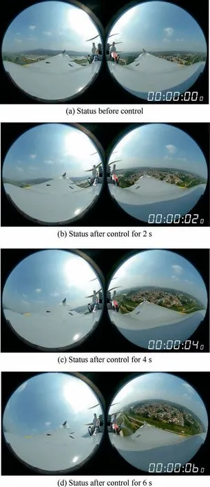
Fig.14 Comparison of flight status before and after control(Left roll).
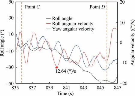
Fig.15 Flight attitude parameter changing process under control of CC effectors (Left roll).
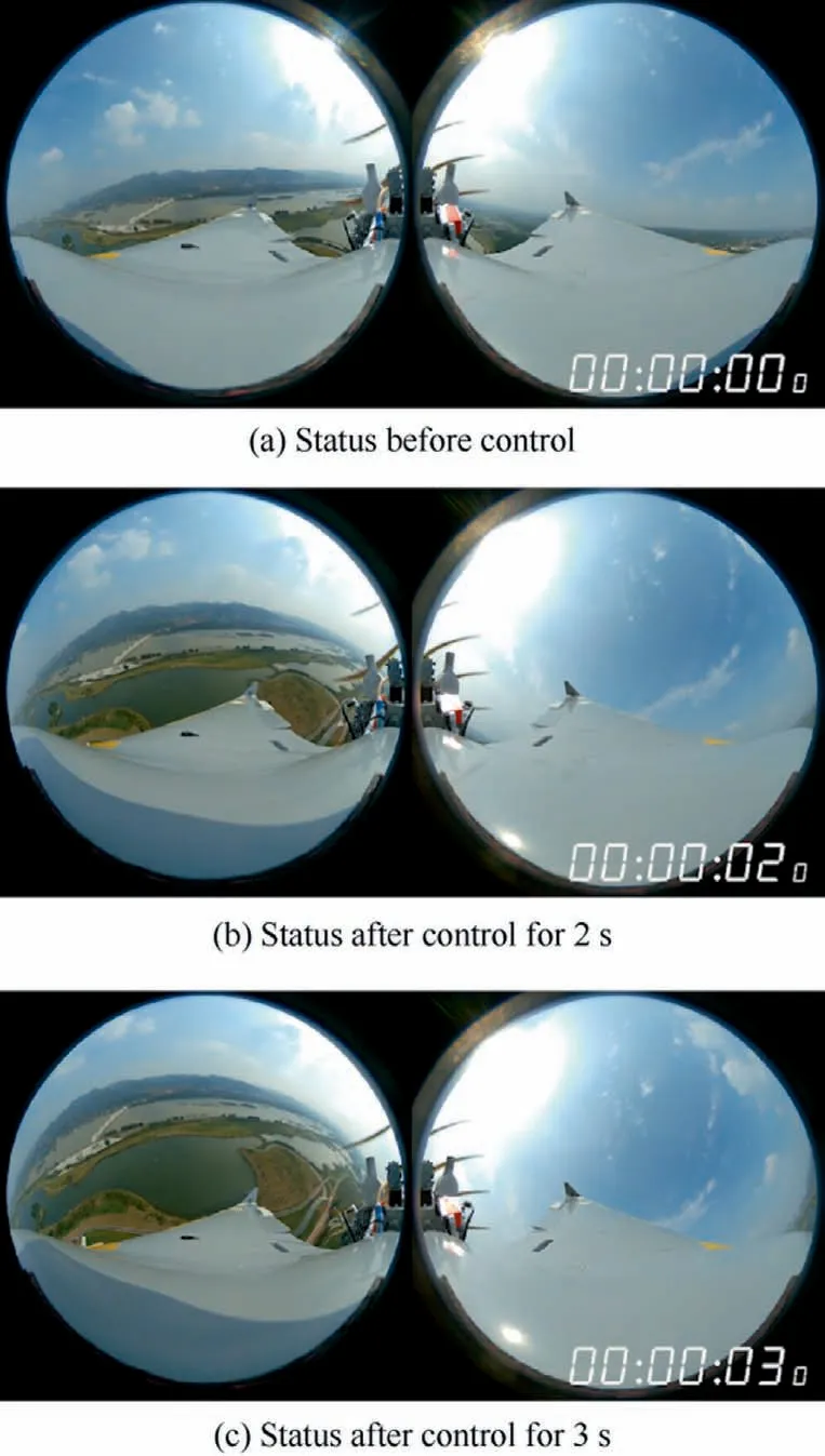
Fig.16 Comparison of flight status before and after control(Right roll).

Fig.17 Flight attitude parameter changing process under the control of CC effectors (Right roll).

Fig.18 Comparison of flight status before and after control(Nose up).

Fig.19 Flight attitude parameter changing process under control of CC effectors (Nose up).
When CC effectors of the right and left wings are simultaneously operated in NCC modes,the comparison of FWA status before and after control is displayed in Fig.18, suggesting that nose-up trend is generated under the control of CC effectors.CC effectors could produce nose-up moment, and hence achieve the control of longitudinal attitudes.In addition, the attitude parameters are shown in Fig.19.At Point C, SJAs start to control FWA without rudders until Point D, showing that nose-up angular velocity could reach 8.51 (°)/s.The pitch angle also has an increasing trend.Similarly, when all CC effectors are working in PCC modes, the comparison of FWA status before and after control is displayed in Fig.20,suggesting that the FWA emerges a nose-down trend.The attitude parameters are shown in Fig.21,indicating that a similar changing process appears and the nose-down angular velocity could reach 8.36 (°)/s.
6.Conclusions
CC effectors are integrated into the trailing ledge of a smallsweep FWA, and numerical simulations are carried out to explore the aerodynamic control characteristics and control mechanism of TE circulation control using SJs.Finally, flight tests are implemented to verify the roll and pitch control ability of CC effectors.Detailed results are exhibited as follows.
CC based on synthetic jets could improve the lift,drag and nose-down moment.The variations of lift and nose-down moment decrease with the growth of AOAs, which means CC only has the ability of controlling roll and pitch attitudes at small AOAs.Synthetic jets could narrow the dead zone area, improve the flow velocity adjacent to the trailing edge,and then push the TE separation point and the LE stagnation point downwards, which make the effective AOA increase,thereby enhancing the pressure envelope area and the lift.The increase of AOAs improves the reverse pressure gradients,which augments the momentum thickness of the boundary layer, weakens the circulation control efficiency, so the lift increment decreases with the growth of AOAs.
Flight tests show that TE SJs could achieve roll and pitch attitude control during curing with the maximum realized roll angular velocity of 12.64 (°)/s and pitch angular velocity of 8.51 (°)/s.In the future, detailed control parameters, such as driving frequency and voltage,will be explored based on wind tunnel tests to establish an aerodynamic control model based on TE SJAs.Moreover, flight tests will be further carried out using the automatic flight control system based on TE SJAs.
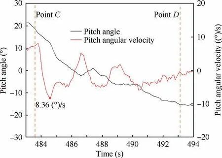
Fig.21 Flight attitude parameter changing process under control of CC effectors (Nose down).
Declaration of Competing Interest
The authors declare that they have no known competing financial interests or personal relationships that could have appeared to influence the work reported in this paper.
Acknowledgements
This work was supported by the National Natural Science Foundation of China (Nos.U2141252, 11972369, 52075538).
 CHINESE JOURNAL OF AERONAUTICS2023年10期
- CHINESE JOURNAL OF AERONAUTICS的其它文章
- Experimental investigation of typical surface treatment effect on velocity fluctuations in turbulent flow around an airfoil
- Oscillation quenching and physical explanation on freeplay-based aeroelastic airfoil in transonic viscous flow
- Difference analysis in terahertz wave propagation in thermochemical nonequilibrium plasma sheath under different hypersonic vehicle shapes
- A parametric design method of nanosatellite close-range formation for on-orbit target inspection
- Bandgap formation and low-frequency structural vibration suppression for stiffened plate-type metastructure with general boundary conditions
- Geometrically compatible integrated design method for conformal rotor and nacelle of distributed propulsion tilt-wing UAV