
Bandgap formation and low-frequency structural vibration suppression for stiffened plate-type metastructure with general boundary conditions
2023-11-10 02:16TianZHAOZhichunYANGYanlongXUWeiTIAN
CHINESE JOURNAL OF AERONAUTICS 2023年10期
Tian ZHAO, Zhichun YANG, Yanlong XU, Wei TIAN
School of Aeronautics, Northwestern Polytechnical University, Xi’an 710072, China
KEYWORDS
Abstract Metastructures with unique mechanical properties have shown attractive potential application in vibration and noise reduction.Typically, most of the metastructures deal with the vibration bandgap properties of infinite structures without considering specific boundary condition and dynamic behaviors,which cannot be directly applied to the engineering structures.In this research,we design a Stiffened Plate-type Metastructure (SPM) composed of a plate with periodic stiffeners and cantilever beam-type resonators subjected to general boundary conditions for low-frequency vibration suppression.The effects of boundary conditions and the number and orientation of the stiffeners on Locally Resonant (LR) type bandgap properties in SPM are further investigated.An analytical modeling framework is developed to predict the bandgap formations and vibration behaviors of SPMs in finite-size configuration.The governing equations of the SPM reinforced by various arrangements of stiffeners are derived based on the first-order shear deformation theory and Hamilton’s principle, and a Fourier series combined with auxiliary functions is employed to satisfy the arbitrary boundary conditions.Finite element analysis and experimental investigations of vibration behaviors for the SPM are carried out to validate the accuracy and reliability of the present analytical model.For practical designs of the SPMs with specific boundary conditions, it is found that there exist optimal numbers of stiffeners and resonators which can produce the significant LR-type bandgap behaviors.Furthermore,various arrangements of stiffeners and resonators are explored for different boundary conditions by breaking the requirement of spatially periodicity.It is shown that for the designed SPM, the vibration modes of its host structure should be considered to widen the frequency range in which the resonators transfer and store energy, and hence improve the performance of low-frequency vibration suppression.The present work can provide a significant theoretical guidance for the engineering application of metamaterial stiffened structures.
1.Introduction
In aerospace science and engineering field, the stiffened plate structures with superior features of load-bearing capacity and better structural strength have been widely used for wings and skins of flight vehicles1,2.During supersonic/hypersonic flight, these structures could suffer severe mechanical, aerodynamic, and acoustic loadings, which could induce serious vibration problems3.For example, during the flight of helicopters, the stiffened plate structures of the airfoil and floor systems always suffer the harmonic excitation from the rotor system4,which could indirectly cause poor vibration environment of airborne equipment, even performance degradation.Hence, the structural vibration problem of the stiffened plate structure is a critical factor to reduce the serviceability and reliability, as well as the performance of flight vehicles.It is of great significance to effectively mitigate these undesired vibrations.So far, a great deal of studies about various vibration control strategies has been carried out5–7.Among these control methods, the passive vibration control has high reliability and needs no additional energy.Nevertheless, it is difficult to meet the requirements in terms of lightweight and loadbearing.Inspired by elastic metamaterials/metastructures,these designs could provide new methods for the vibration reduction of the structures owing to their unique dynamic characteristics, such as bandgap8, directional propagation9and wave absorption10.
Elastic metamaterials/metastructures could prohibit the waves in a certain frequency range to propagate along the periodic substructure and achieve the vibration suppression based on the Local Resonance (LR) mechanism and Bragg Scattering (BS) mechanism11,12.The studies for bandgap behaviors of elastic waves in periodically stiffened plates have attracted considerable attention since the early studies of Mace13,14and Mead et al.15–17The wave propagation and far field sound radiation behaviors of an infinite sandwich structure reinforced by orthogonal rib-stiffeners were analytically studied by Xin and Lu18,and they examined the influences of the inertial effects of rib-stiffeners, excitation position and ribstiffeners spacing, respectively.Afterwards, Li et al.19utilized the Finite Element(FE)method and Bloch periodic boundary conditions to analyze the flexural wave bandgaps and vibration attenuation of an infinite stiffened plate.Similarly, the beam-type flexural wave propagation behaviors in orthogonally stiffened plates are theoretically and experimentally investigated by Tang et al.20.However,the flexural wave bandgap of periodic stiffened plates is mainly concentrated on medium and high frequency, which is difficult to solve the lowfrequency vibration suppression and isolation.
The LR-type bandgap could be generated in the deepsubwavelength regime using a lattice constant much smaller than the operating half-wavelength at the resonance frequency,which breaks the limitation of BS mechanism.To strengthen the performance of low-frequency vibration suppression and isolation, various studies have investigated on the metastructure (i.e., locally resonant metamaterial-based finite structures), which can be constructed by attaching arrays of local resonators to a host structure (such as rods21, beams22–24and plates25,26).Sun et al.27presented a comprehensive study of infinite periodic locally resonant beams, and performed numerical studies for finite locally resonant beams.It showed that, for low-frequency excitation, metamaterial designs require consideration of the boundary conditions and resonant modes of the structure.According to unit-cell based dispersion analysis, Xiao et al.28–30developed efficient formulas for bandgap estimation, and analyzed the bandgap formation mechanisms of such metastructures.Peng et al12,31revealed the work mechanism of metamaterial plates for elastic wave absorption and structural vibration suppression by periodically attaching the locally resonant units.Zouari et al.32investigated both infinite and finite models, and proposed an automatic method to obtain the bandgap frequency range of finite metamaterial structure.Wang et al.33proposed a metamaterial sandwich plate with periodically distributed platetype resonators, and analyzed its bandgap properties.Li et al.34studied the band gaps and vibration isolation of a sandwich plate-type metamaterials theoretically and experimentally.Similarly, Chen et al.35presented a sandwich plate-type metastructure to solve the low-frequency vibration and noise control, and corresponding experiments were conducted to verify its superior performance of vibration isolation.Song et al.36analyzed the vibration and sound radiation of the metamaterial sandwich panels.Numerical and experimental results showed that the vibration, sound radiation and sound transmission of the metamaterial panels are reduced over wide frequency ranges.More recently, a metamaterial stiffened panel was proposed by Tian et al.37,which provided an excellent vibration and supersonic flutter suppression.At present,the analytical predictions for bandgap formation are mostly obtained based on the assumptions of travelling elastic wave.These infinite-size metastructures are generally made from a repeated unit cell without considering both the information of specific boundary condition and modal behavior; hence, cannot be applied to the actual engineering structures.So far, Sugino et al.38–40developed a method for understanding the LR-type bandgap in metastructures with specified boundary conditions based on the modal analysis.Using the modal analysis approach, Zhao et al.41studied the effect mechanism of mode localization of the Ttype resonator on the bandgap formation of a plate-type metastructure.El-Borgi et al.42derived multiple bandgap formation for the vibration suppression of locally resonant elastic metamaterial beam.They obtained the bandgap behaviors of the metastructure with finite dimensions and a finite number of local resonators.
Modeling and dynamic analysis of stiffened plate structures have been a topic of research since the early studies of Lamb43and Ungar44.Yu et al.45adopted a time-domain spectral finite element method to study the wave field in stiffened plate,and the effects of the parameters of the stiffener on wave propagation are also investigated.Liew et al.46,47firstly established the dynamic model of rectangular plate with intermediate stiffeners based on the Rayleigh-Ritz approach, and numerically analyzed the effects of torsional rigidity and geometric properties of stiffeners.Based on the Mindlin theory (applied for plate), the Timoshenko beam (applied for stiffeners) and the numerical simulation technique, Cho et al.48studied the free vibration of a stiffened panel carrying elastically attached lumped masses with arbitrary sets of boundary conditions.Using mixed analytical–numerical techniques, Zhou et al.49analyzed the free and forced vibrations of sandwich plates Z-reinforced by steel ribs and conducted corresponding experiments.Additionally, Zhang and Lin50presented an analytical solution for the vibration response of a beamstiffened Mindlin plate by using a modal expansion solution approach.Later on,they51utilized a double finite sine integral transform technique to solve the vibration response of an orthogonally ribbed isotropic plate, and found that it could produce a matching response of orthotropic plate by adjusting the number and properties of ribs.Gao et al.52utilized a semianalytical method to analyze the free, steady and transient vibration behaviors of stiffened plate with general boundary conditions.Hu et al.53investigated the dynamic behavior and sound transmission of the functionally graded material plates with general boundary conditions.
The above-mentioned brief review of the exiting literatures indicates that,although the dynamic behaviors of the stiffened plate and the flexural wave propagation behaviors in periodically stiffened plate have been studied, an accurate theoretical modeling of LR-type metamaterial-based design of stiffened metastructures with arbitrary(classical,elastic)boundary conditions has not been reported in the existing literatures.Besides, the effects of boundary conditions and the number and arrangement of the resonators and stiffeners on LR-type bandgap properties of Stiffened Plate-type Metastructure(SPM)should be concerned to well guide their design in vibration control application.This work is an exploration of the LR-type stiffened metastructure into the aerospace structures,such as the vibration problem of reinforced helicopter floor structure exposed to periodic excitation.
In the present paper,we introduce the concept of the locally resonant metamaterial to the study of vibration reduction of stiffened plate structures in the aerospace engineering field.Based on the first-order shear deformation theory and the modal analysis approach, we establish a unified model of the SPM with arbitrary boundary conditions to predict the bandgap formations and vibration behaviors of SPMs in the finitesize configuration.The proposed analytical model can be adopted to obtain the dynamic characteristics of stiffened plates under arbitrary boundary conditions, and the obtained results can be directly used to the dynamic design of practical engineering structures.In addition, we explore the influences of the number and distribution of stiffeners and resonators on the bandgap behaviors and vibration suppression performance for the SPM, which is also different and goes further from our recent work37.This paper is organized as follows.The governing equations of the stiffened plate-type metastructure with general boundary conditions are formulated and its bandgap edge frequencies are derived in Section 2.In Section 3,the feasibility and accuracy of the proposed theoretical model are numerically and experimentally validated.Section 4 evaluates the influences of the number and distribution position of resonators and stiffeners on the bandgap behaviors.Section 5 presents time-domain vibration analyses to demonstrate the potential application of the proposed SPM in the vibration suppression of the engineering system.Finally,the conclusions are drawn in Section 6.
2.Theoretical analyses
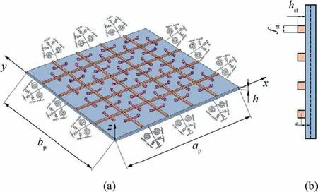
Fig.1 (a) Schematic of the SPM with a distributed array of cantilever beam-type resonators (b) Cross section of the stiffened plate.
As shown in Fig.1(a), a Stiffened Plate-type Metastructure(SPM) that consists of a host stiffened plate and periodic arrays of cantilever beam-type resonators is designed based on the locally resonant metamaterial theory.The arbitrary condition boundaries are sketched by introducing edge supporting springs on the stiffened plate with length ap,width bpand thickness h.The schematic of the cross section of the stiffened plate is illustrated in Fig.1(b), where stiffeners are considered as beams with uniform rectangular cross section fst× hst.In addition, the stiffeners can be designed with arbitrary angles and various arrangements.The typical cases for two-direction arrangement (one x-direction and one y-direction) and one-direction arrangement (only x-direction)are discussed in this study.The number of stiffeners is defined as Nst(Nst= Nxst× Nyst, Nxst= Nystis for two-direction arrangement; Nst= Nxstis for one-direction arrangement),with Nxstand Nyststiffeners evenly spaced along the x and y dimensions, respectively.Besides, NRcantilever beam-type resonators are evenly distributed along the length of each stiffener for the SPM.
2.1.Energy expressions of SPM
The potential energy and kinetic energy of the SPM(including the plate, stiffener and cantilever beam-type resonator) are derived in this section.Based on the first-order shear deformation theory, the displacement components of the plate in the x-, y-, and z-directions are written as
where up,vp,and wpare the displacements on the middle plane of the plate in the x-,y-,and z-directions,respectively;φpand ψpare the transverse rotations normal to the middle plane about the x-and y-axes,respectively.The strain and curvature of the middle plane are given as
The constitutive relations of the plate are expressed as
Similarly, the displacement components of the stiffeners in the local coordinate based on the first-order shear deformation theory are described as
where ust, vstand wstare the displacements at the neutral axis of the stiffener; φstand ψstare the rotations.Using the transformation matrix from the global to local coordinate system,we can describe the displacement vector ustof the stiffener in terms of the displacement vector upof the plate based on the continuous conditions on the interface:
where α is the angle between stiffener tangential direction and x-axis.Furthermore, α = 0 for x-direction stiffeners and α=π/2 for y-direction stiffeners.The compatibility condition can be satisfied by introducing the eccentricity e=(h+hst)/2 in Eq.(5).Thus,the potential energy Upand kinetic energy Tpof the plate are deduced as follows
The stain energy and kinetic energy of stiffener are expressed as:
where
mst=diag{Ast,Ast,Ast,Iz,J}ρm,in which L,Gmand ρmare the length,shear modulus and density of stiffener,respectively;Ast, Izand J denote the cross-section area, second moment about the z-axis and torsion constant of stiffener,respectively,which are given as follows
The cantilever beam-type resonator can be simplified as a Single Degree of Freedom (SDOF) linear resonator using its first transverse bending mode, whose frequency is obtained by introducing the equivalent mass mr,jand stiffness kr,j.The corresponding potential energy and kinetic energy of the jth cantilever beam-type resonators are expressed as
where dj, ρj, Ar,j, Er,jand Ir,jdenote the overhang length, density, cross-sectional area, elastic modulus and inertia moment of the jth beam resonator, respectively.Mjis the tip mass attached to the end of the jth beam resonator.
For the practical boundary constraints of the engineering structure, the elastic support boundaries can be used to analyze the influence of restrains on the vibration characteristics.We utilize the virtual spring technique to realize the different elastic boundary conditions for the SPM.The deformation elastic potential energy stored in the edge supporting springs is written as
It should be noted that the stiffness coefficient values of these edge supporting springs in Eq.(13)depend on the specifically given boundary conditions.The total energy function of the SPM can be obtained as
2.2.Solution methodology
The displacement components of the SPM can be expressed as the Fourier series combined with auxiliary functions54to satisfy the cases of classical or non-classical boundary conditions,given by
in which λm=mπ/ap, λn=nπ/bp(m=1,2,∙∙∙,M;n=1,2,∙∙∙,N).M and N indicate the number of truncations in the series.H is the vector of Fourier cosine series combined with auxiliary functions.Qu, Qv, Qw, Qxand Qydenote the generalized coordinate vectors.
The auxiliary functions ξ1a,ξ2a,ξ1band ξ2bare introduced to overcome the discontinuity problem on the edges of the plate,which are described by polynomial functions:
It can be found that,
which shows that the first-order partial derivatives of the given admissible functions are continuous at the edges of the plate.In addition,and(i=1,2,∙∙∙,6) are the corresponding supplement coefficients.Corresponding details are given in Appendix A.
The governing equations for the SPM can be derived based on the Hamilton principle.Substituting the energy expressions of the plate, stiffeners and resonators into Eq.(14), together with the displacement functions given in Eq.(15), and setting the total energy functional δΠ to zero, which yields
where qp=[Qu,Qv,Qw,Qx,Qy]Tand qr=[p1,p2,∙∙∙,pNR]Tdenote state vectors of the stiffened plate and cantilever beam-type resonators,respectively.F is the vector of the external excitations.The expressions of matrices and vectors MP,KP,Mst,Kst,MR,KR,KSand KCare provided in the Appendix B.According to Eq.(18), the dynamic responses of the SPM can be attained when it is subjected to a harmonic excitation F=F0eiΩt.
2.3.Bandgap formation using modal analysis approach
The previous studies of Sugino et al.40have investigated the LR-type bandgap in a finite metastructure using the general operator formulation.By extending this method, we derive the bandgap expressions for the SPM considering the effects of the periodical stiffeners and cantilever beam-type resonators.As deduced in the following context in this section,the transverse motion of the metamaterial plate attached with resonators will be obtained.Here,a variable yjwhich describes the relative displacement of the resonator with respect to the transverse displacement of the plate is expressed as
For the linear structure,we assume that the responses of the metastructure and the resonators are harmonic at the given excitation frequency Ω, and employ an overhead bar to indicate the steady-state amplitude of the dynamic response, i.e.,yj=y-jsin(Ωt), qp=q-psin(Ωt).Thus, the steady-state amplitudes of the resonators can be described by
Substituting Eq.(22) directly into Eq.(20), we obtain
For sufficiently large NRand assuming the resonators attachment locations (xj, yj) are evenly well distributed, based on the orthogonality of the mode shapes, the Riemann sum approximation is utilized, i.e.,
Eq.(25) can be solved explicitly for the steady-state amplitude of the structure ˉqp, with a closed-form expression as
Dividing both the numerator and denominator byyields
The roots of the polynomial in the denominator give the new resonant frequencies associated with each mode.The two positive roots of the denominator of Eq.(27)are deduced as:The frequency range obtained by the analytical method defines the limits of the bandgap and provides an easy method for locating the bandgap at a designed frequency range.This agrees with the result obtained by unit-cell dispersion analysis30,where they found the bandgap edge frequencies in a plate with attached resonators.The normalized bandwidth of the bandgap resulting from the limit analysis is presented as
3.Validation studies
In this section, the feasibility and accuracy of the proposed analytical model to analyze the bandgap characteristics and vibration behaviors of the SPM are validated numerically and experimentally.The plate is made of aluminum with material properties: Em= 7.9 × 10¹⁰Pa, ρm= 2810 kg/m3,νm= 0.33.The material properties of stiffener are Est= 6.2×10¹⁰Pa,ρst=2700 kg/m3,νst=0.33.The shear correction factor κsis taken as 5/6.For all case studies, the geometrical parameters of the SPM are set as ap= bp= 1.0 m,h = 0.01 m, fst= 0.01 m, hst= 0.01 m, unless stated otherwise.The external excitation is exerted at (xin, yin) = (0.1 m,0.3 m), and the response point is set at PA(x, y) = (0.7 m,0.65 m).
3.1.Numerical validation
Firstly, the effects of edge supporting springs on the natural characteristics of the stiffened plate are analyzed to determine proper values for various boundary conditions.In the present study, linear restrain springs (ku, kv, kw) and rotation restrain springs(kx,ky)are introduced to separately simulate the different boundary conditions.For example,the clamped boundary condition (C) is obtained when all spring stiffness coefficient values on each plate boundary are set to infinity.Conversely,the free boundary condition(F)can be realized by setting stiffness coefficient to 0.As shown in Fig.2, the first two natural frequencies of the stiffened plate converge to stable values when the stiffness coefficients of edge supporting springs exceed 1 × 10¹⁰.Hence, the theoretical infinite spring stiffness coefficient representing the clamped boundary condition is replaced by a large value 1×10¹⁰.Besides,the edge supporting springs with actual stiffness coefficient values can be designed to obtain the expected elastic boundary condition.
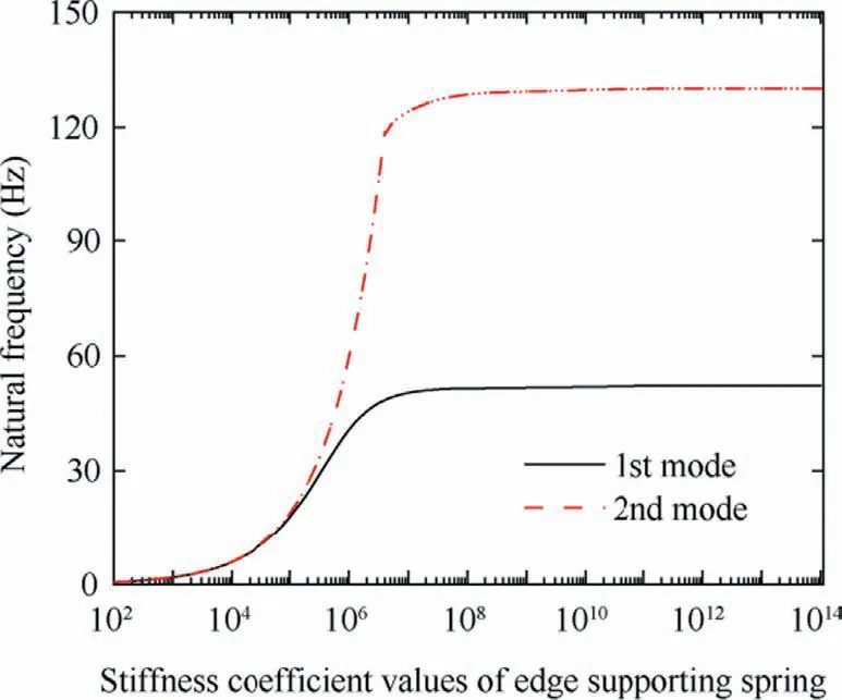
Fig.2 Natural frequencies of stiffened plate with four edges simply supported(S-S-S-S)varying with stiffness coefficient values of edge supporting springs.
Next, the effectiveness and accuracy of the analytical method of the present SPM are validated by comparing with the Finite Element (FE) method.Figs.3(a) and (b) show the comparisons of the amplitude-frequency curves for the stiffened plate and SPM,respectively.The SPM with a simply supported boundary involves a uniform distributed two-direction stiffeners (Nxst= Nyst= 4).The cantilever beam-type resonators (NR= 5) are evenly distributed on each stiffener of the SPM, in which all the resonators are tuned to produce a bandgap aimed at the second frequency of the stiffened plate.As expected, the effect of cantilever beam-type resonators becomes remarkable near the second mode, and the corresponding peak is suppressed substantially.It is clearly seen that the curves are well overlapped,indicating that the analytical model has a good agreement with the FE model.Besides,the LR-type bandgap generated by the SPM is marked by the shaded region in Fig.3(b).To demonstrate the accuracy of bandgap estimation, Fig.4 depicts the resonant frequencies of the metastructure as a function of ωpwith μr=0.1 according to Eqs.(28a) and (28b).It is found that the limiting frequencies of the upper and lower bandgap edges are in consistency with the edge frequencies of shaded area in Fig.3(b).

Fig.4 Resonant frequencies of SPM as a function of resonant frequency of host stiffened plate with μr = 0.1.
In addition, a comparative study of amplitude-frequency curves for various boundary conditions is listed in Fig.5.The corresponding arrangements of the stiffeners and resonators are annotated in the top right of the figures.It should be mentioned that different arrangements of stiffeners and resonators are adopted for the stiffened plate considering the vibration modes of the stiffened plates.Particularly, the host plate with one-edge clamped is reinforced by one-direction stiffener,and this case is validated experimentally later in Section 3.2.For the host plates with their four edges clamped (or simply supported), they are reinforced by the two-direction stiffeners arrangement.Obviously, the unified formulation developed in this study can provide a good agreement with the FE method.Owing to the tuned resonators designed for the first mode of the host stiffened plates, the corresponding bandgap is generated and the vibration response of the SPM near its first frequency is significantly suppressed.Consequently, the aforementioned results indicate that the present analytical model has the capability to accurately predict the bandgap and vibration behaviors of SPMs with various boundary conditions and stiffener arrangements.Furthermore, the present formulas can serve as efficient tools that enable a fast preliminary design of bandgaps for the SPMs.
3.2.Experimental validation

Fig.3 Comparison of amplitude-frequency curves of(a)the stiffened plate and(b)the SPM with four edges simply supported(S-S-S-S)for the analytical model and FE model with μr = 0.1.
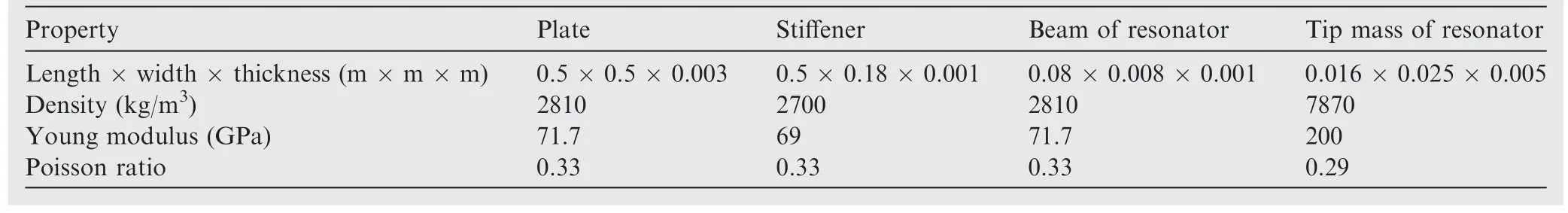
Table 1 Parameters of SPM.
In this section, the experimental validation for the SPM with one-edge clamped (C-F-F-F) is carried out.The geometrical parameters and the material properties of the SPM with the distributed cantilever beam-type resonators are shown in Table 1.The cantilever beam-type resonator consisting of an aluminum beam and a steel block on the tip of one side is clamped symmetrically on the stiffener via two screws and nuts.Fig.6 shows the experimental setup of the SPM.The Real-time semi-physical simulation system (Quarc, QUANCER)generates the excitation signals and drives a MB electromagnetic shaker (JZK-10, Sinocera) to excite the SPM via a high voltage amplifier (YE5872A, Sinocera), and a force sensor is used to measure the force exerted on SPM.The data acquisition system (LMS) is used to identify the mode shapes,and accelerometers are used to measure the acceleration responses of the response points (P1(x, y) = (0.45 m,0.3 m), P2(x, y) = (0.49 m, 0.22 m)).The external excitation is exerted at (xin, yin) = (0.1 m, 0.3 m).The amplitudefrequency curves are then provided by recording the steadystate amplitudes of the response points of the SPM.
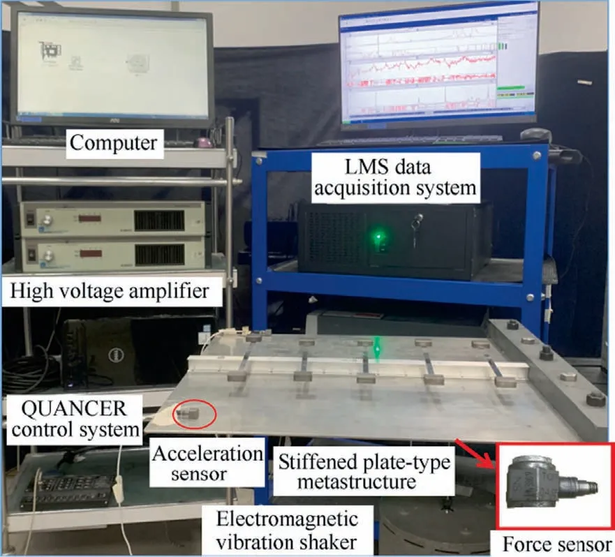
Fig.6 Experimental vibration setup of SPM.
At first, a modal test for the stiffened plate is conducted to obtain accurate estimates of its first four natural frequencies and mode shapes.The experimental and analytical results of the stiffened plate are both presented in Fig.7, which shows the excellent agreements.Then, the cantilever beam-type resonators with NR= 10 are designed to alleviate the vibration response of the first mode of the stiffened plate.Subsequently,the sweep sine tests for the stiffened plate and SPM are performed to obtain the steady-state amplitude of two response points, respectively.The acceleration responses obtained by the experimental tests for the stiffened plate and SPM are shown in Fig.8, which agree well with the analytical results and FE results.Besides, as shown in Figs.8(c) and (d), the two new peaks near the first mode of the stiffened plate,as well as a significant attenuation in the vibration of the response points near the resonant frequencies, can be identified clearly.Therefore,it is experimentally demonstrated that the proposed metastructure has the capability to form the specific bandgap for vibration suppressions.
4.Finite-size SPM design and performance assessment
This section is devoted to elaborate the bandgap behaviors and performance of vibration suppression of SPMs bearing finite numbers of stiffeners and resonators considering different boundary conditions.Two cases of stiffener arrangements,i.e., two-direction or one-direction stiffeners, are presented in Fig.9.The optimal number of resonators for a given SPM with specific boundary condition that can form the LR-type bandgap is obtained.Here, the total mass for the stiffeners and resonators remains unchanged in the following studies.Besides, the cantilever beam-type resonators are evenly distributed in each stiffener (nR=NR/Nst) and they are designed with the same mass mr=μr(mp+mst)/NRand natural frequency ωrfor the limitation of the number of independent variables.
4.1.Finite number of resonators
The bandgap expression of the SPM is exact for the infinite number of uniformly distributed resonators based on the Riemann sum approximation Eq.(24).Yet, it is crucial to explore the evolutions of the bandgap behaviors by changing a reduced number of resonators for a finite-size SPM.Figs.10(a) and (b) give the nephograms of vibration displacement response versus NRfor the SPM (S-S-S-S) reinforced by twodirectional stiffeners (Nxst= Nyst= 2) with μr= 0.3 and μr=0.5,respectively.Here,the transverse bending frequencies of the resonators are tuned to the second mode of the stiffened plate.In both cases,the bandgap of the SPM is represented by a sharp reduction of vibration amplitudes across a wide frequency range, marked by the blue regions from the figures.It is clearly seen that the bandgap converges to a fixed frequency range given by Eq.(29) (limits of which are marked by the horizontal dashed lines), as the number of resonators becomes sufficiently large.These results show that a larger number of resonators do not mean a wider bandgap,and there is an optimal resonator number for the SPM with a given boundary condition and stiffener arrangement.

Fig.7 Comparisons of the first four frequencies and mode shapes obtained by the analytical method and experiments.

Fig.8 Amplitude-frequency curves for (a) P1 and (d) P2 of the stiffened plate; for (c) P1 and (d) P2 of SPM.
Similarly, the case of SPM (S-S-S-S) with one-direction stiffeners(Nxst=4)is also investigated in Fig.11,which indicates that two types of stiffener arrangements can both create a LR-type bandgap.For the case of one-direction stiffener arrangement, there also exists an obvious convergence with the increasing of resonator number.It is noted that the optimal number of resonators will vary for various types of SPMs with different combinations of boundary conditions, due to the changes of mode shapes of the system.Furthermore, it is found that the suppression bandwidth becomes broader with the increasing of the total mass of resonators,which can attain a better vibration control performance for the SPM.It also corroborates the conclusion of bandgap broadening technique by increasing the additional resonator mass29.
4.2.Finite number of stiffeners
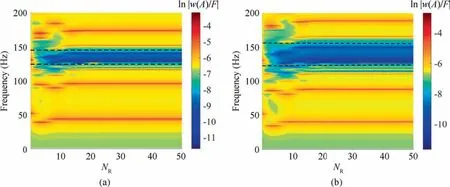
Fig.10 Vibration displacement responses of SPM (S-S-S-S) with two-direction stiffeners varying the number of resonators for (a)μr = 0.3; (b) μr = 0.5; Horizontal dashed lines indicate the predicted LR-type bandgaps using infinite resonator approximation.

Fig.11 Vibration displacement responses of SPM (S-S-S-S) with one-direction stiffeners varying the number of resonators for (a)μr = 0.3; (b) μr = 0.5; Horizontal dashed lines indicate the predicted LR-type bandgaps using infinite resonator approximation.
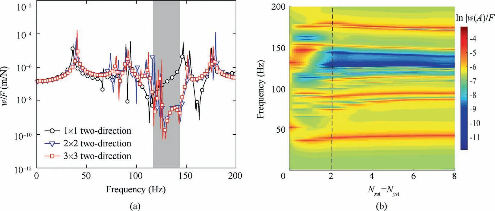
Fig.12 (a)Amplitude-frequency curves of SPM(S-S-S-S)with two-direction stiffeners varying with the number of stiffeners for μr=0.5 with Nxst = Nyst = 1–3; (b) Nephogram of vibration displacement response versus Nxst /Nyst for SPM with two-direction stiffeners for μr = 0.5.
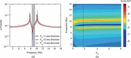
Fig.13 (a) Amplitude-frequency curves of SPM (C-F-F-F) with one-direction stiffeners arrangements varying with the number of stiffeners for μr = 0.7 with Nxst = 1–3; (b) Nephogram of vibration displacement response versus Nxst for the metastructure with onedirection stiffeners for μr = 0.7.
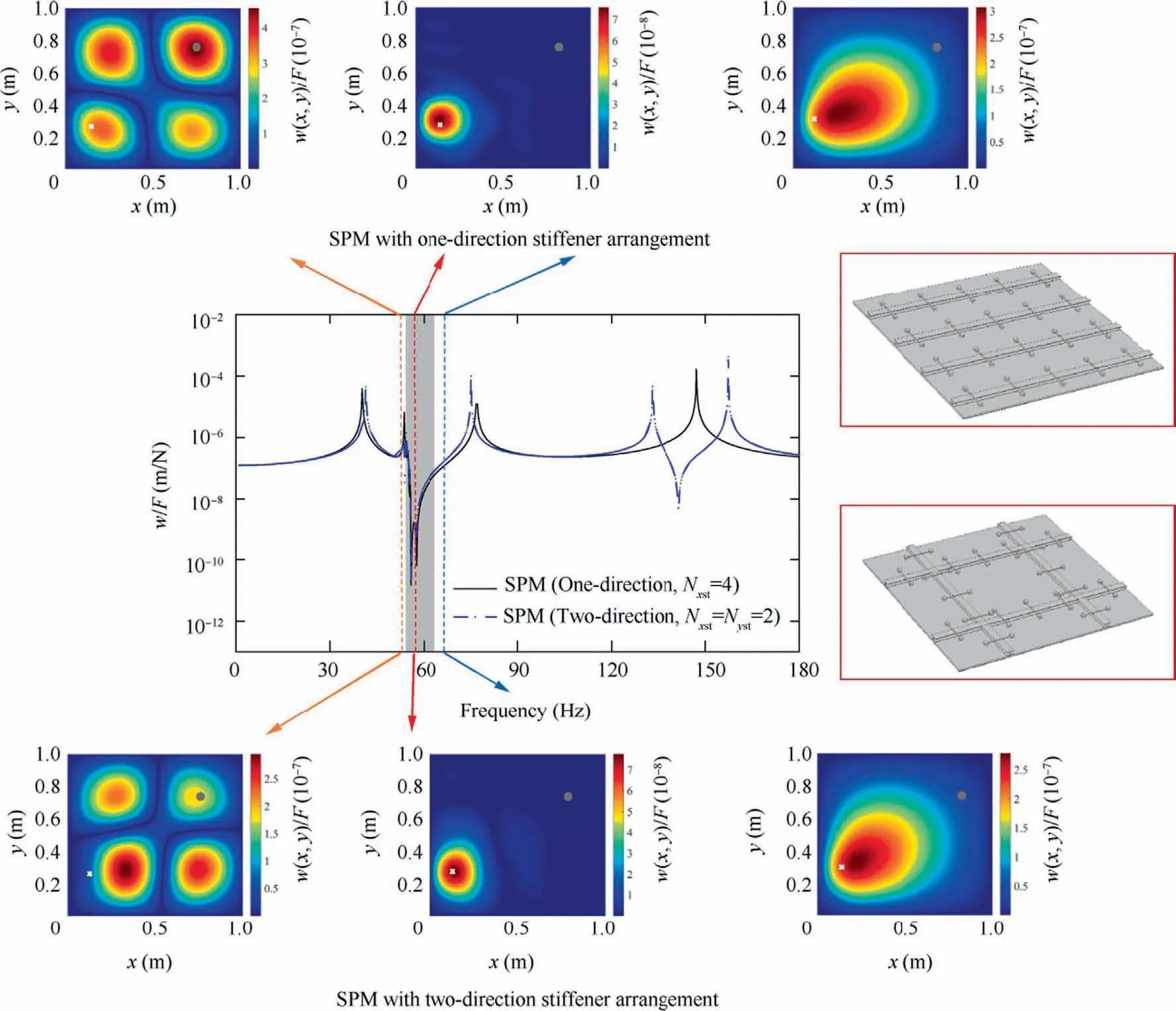
Fig.14 Amplitude-frequency curves of SPMs (S-S-S-S) considering two different stiffener arrangements.The LR-type bandgap predicted by Eq.(29)is shown by the shaded gray region.The inserts show the real part of the transverse displacement of the entire SPMs for frequencies before,inside and after the bandgap(Ω=55 Hz,57 Hz and 65 Hz,respectively).In each inset,the input force location is shown by a white point, and the output PA is shown by a grey circle.The SPM models with two different stiffener arrangements are illustrated in the right side.
Since the Riemann sum approximation has no restrictions on the locations of resonators, the effects of distributed stiffeners and resonators on the bandgap behaviors of the SPM are analyzed in this subsection.The total number of resonators (attached evenly in each stiffener) is set the same as NR= 24,owing to the LR-type bandgap generated by a finite number of resonators.By tuning the number of stiffeners, we can obtain different distributions of stiffeners and resonators.For the SPM (S-S-S-S) reinforced by two-direction stiffeners,Fig.12(a) shows the comparisons of amplitude-frequency behaviors for the SPMs (Nxst= Nyst= 1–3).It can be seen that the vibration response of the second mode in all the cases can be suppressed effectively.However,for the case of Nxst=Nyst=1,it is different from the others,and the bandgap cannot be formed.The nephogram of vibration responses versus the number of stiffeners for the SPM with μr= 0.5 is shown in Fig.12(b).With the increasing of stiffeners number, the bandgap phenomenon can be observed.Interestingly,the stiffeners with Nxst=Nyst=2(marked by a vertical dashed line)can lead to a wider LR-type bandgap.Thus,although the infinite number assumption for the resonators can provide a straightforward technique to evaluate bandgap formation,there exists an ‘optimal’ arrangement of resonators for broadband vibration suppression.
For the case of one-edge clamped, the vibration behaviors of the SPM reinforced by different number of x-direction stiffeners with μr=0.7,and the corresponding nephogram of displacement response versus Nxstare given in Figs.13(a)and(b),respectively.A significant suppression can be achieved in the proximity of the first mode.The result shows that the SPM with Nxst=1 stiffener can create a significant bandgap,which can also determine the optimal number of stiffeners for the case of one-edge clamped(annotated by a vertical dashed line).These types of arrangements of stiffeners and resonators have broken the requirement of periodic unit-cell.For the finite-size structure with specific boundary condition,the existence of the optimal arrangement for stiffeners and resonators indicates that it may be inefficient to install the excessive stiffeners and resonators on the structure.In particular, certain resonators installed on the irrelevant locations will cause the reduction of energy transmission.Therefore, the number and arrangement of resonators and stiffeners should be designed for enhancing energy transfer efficiency and suppression bandwidth of the SPM, considering the plate geometrical parameters, boundary conditions and stiffener arrangements.

Fig.15 Amplitude-frequency curves of SPMs (C-F-F-F) considering two different stiffener arrangements.The LR-type bandgap predicted by Eq.(29)is shown by the shaded gray region.The inserts show the real part of the transverse displacement for the entire SPMs for frequencies before,inside and after the bandgap(Ω=9.0 Hz,10.2 Hz and 11.6 Hz,respectively).In each inset,the input force location is shown by a white point,and the output PA is shown by a grey circle.Models of the SPM with two different stiffener arrangements are illustrated in the right side.
5.SPM design for vibration suppression application
Since the stiffened structures used in the aircraft are hard to satisfy the requirement of the periodic design for stiffeners,we examine the effects of the stiffener arrangement on the bandgap behavior of the SPMs with specific boundary conditions based on the obtained optimal number of the stiffeners.A proper design scheme for the SPM is proposed to achieve a superior performance of vibration suppression.In particular,the reinforced helicopter floor structures are generally exposed to severe periodic load excitation, which may produce significant vibration problem and structural fatigue damage.Thus,the case of the vibration control application of the SPM under the rotor excitation is presented, and the corresponding timedomain response analyses of the response point are conducted.
Taking the cases of SPMs with two types of boundary conditions (S-S-S-S and C-F-F-F) as examples, we evaluate the effects of the stiffener arrangement on the bandgap behaviors and vibration suppression performance of the SPMs based on the obtained optimal numbers of resonators and stiffeners.The geometrical parameters of the stiffeners are set as fst=0.01 m,hst=0.02 m.Fig.14 compares the amplitude-frequency curves of the SPMs (S-S-S-S) reinforced by two-direction stiffeners and one-direction stiffeners.Here, the numbers of stiffeners(two-direction stiffeners Nxst= Nyst= 2 and one-direction stiffeners Nxst=4)and the resonators(each stiffener is evenly attached with NR=5 resonators)are the same.It can be seen that SPMs can both form an obvious LR-type bandgap and mitigate substantially the vibration response of the first mode.Although the arrangements of stiffeners and resonators are totally different, the suppression regions of the bandgaps are overlapped, which are related to the additional mass ratio.According to Eq.(29), the additional mass ratio determines the width of the bandgap.Hence, for the case of S-S-S-S, the arrangements of stiffener and resonator have little influence on the bandgap formation.By breaking through the limitation of spatially periodicity, we can design different types of SPMs according to the requirement of practical engineering structure.However,it should be noted from Fig.14 that the second frequencies for the two kinds of SPMs are apparently distinct,which shows that the stiffener distribution can affect the inherent characteristic of the structure, including the natural frequencies and mode shapes of the host plate.Additionally,the transverse displacements for the entire SPM at the response point PAare presented in the illustrations.The frequencies are chosen before,inside and after the bandgap(Ω=55 Hz,57 Hz and 65 Hz),respectively.It is clearly seen from Fig.14 that the vibration responses of the full SPM are entirely suppressed at the bandgap frequency.Comparing these illustrations,the two types of stiffener arrangements both produce excellent and similar vibration control performance for the present boundary condition (S-S-S-S).
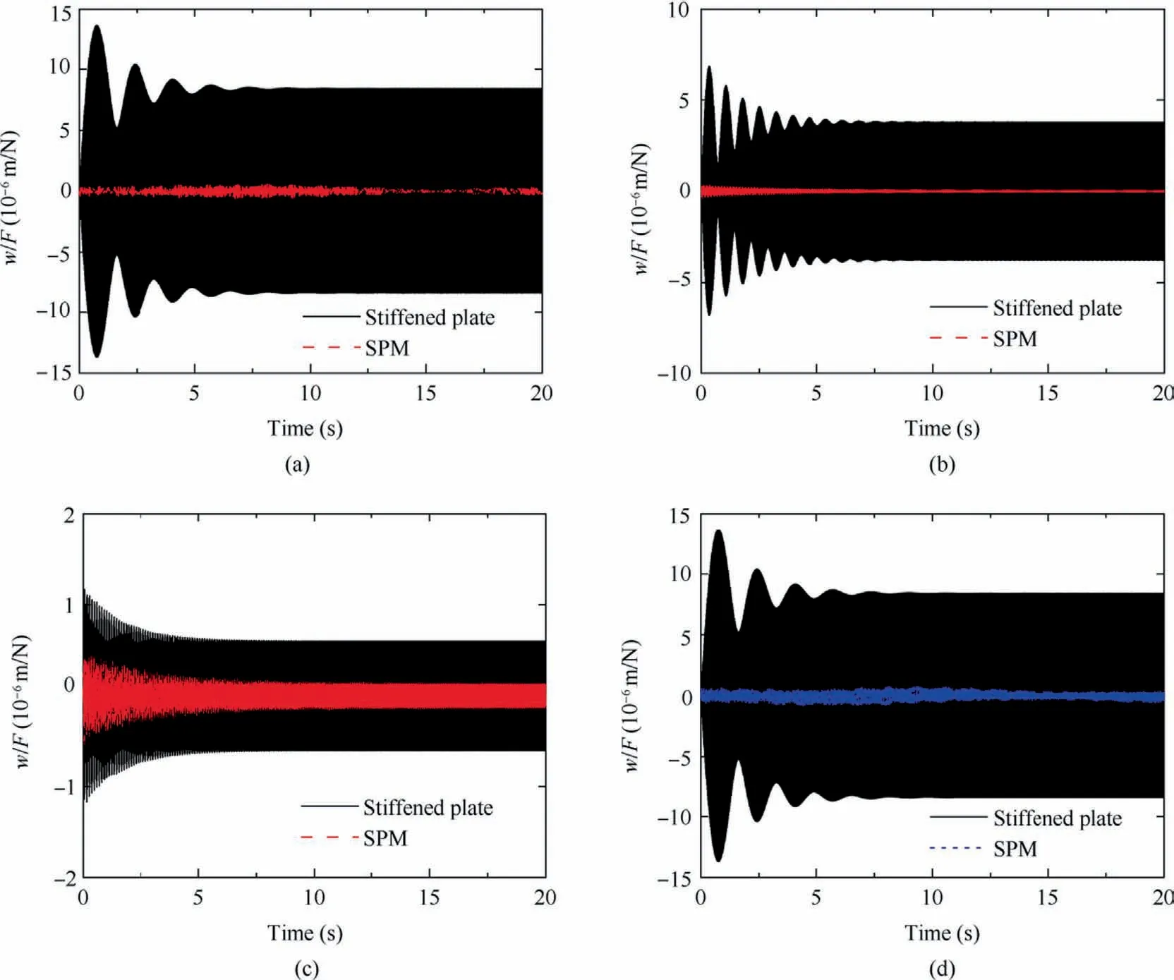
Fig.16 Time-domain response of SPM (S-S-S-S) with two-direction stiffeners arrangements under (a) Ω = 55 Hz; (b) Ω = 57 Hz; (c)Ω = 65 Hz; (d) dual-frequency excitation.
The cases for the SPMs considering two different stiffener arrangements with one-edge clamped are shown in Fig.15.We set Nxst=Nyst=1 for the two-direction stiffeners and Nxst=2 for the one-direction stiffeners.The transverse displacements for the entire SPM are also displayed with frequencies before, inside and after the bandgap (Ω = 9.0 Hz, 10.2 Hz and 11.6 Hz, respectively).These two types of stiffener arrangements still can create an obvious LR-type bandgap,even though they are aperiodic and break the requirement of spatially periodic arrangement based on unit-cell dispersion analysis.It can be seen from the amplitude-frequency curves that the left regions of the bandgap are relatively insensitive to the specific arrangement,characterized by a sharp reduction in vibration amplitude.Nevertheless, there exists a difference in the right regions, which shows that the arrangement of one-direction stiffeners can form a wider bandgap.This is because the energy transmission of the resonators is related to the installation positions, and depends on the vibration mode of the stiffened plate.Meanwhile, the influence of the stiffener arrangement on the natural frequencies and mode shapes of the host stiffened plate should be considered in the design of distribution of the stiffeners and resonators.Such a design can enhance the frequency range at which the resonators transfer and store energy.According to the vibration level of the entire SPM shown in Fig.15, the results of onedirection arrangement are lower than those of two-direction by comparing maximum value of the right color legend of the illustrations.Therefore, the one-direction stiffeners arrangement is suitable for the case of the one-edge clamped.The present work demonstrates that a proper arrangement of stiffeners and resonators for SPMs with various boundary conditions can achieve the enhanced performance of the broadband low-frequency vibration attenuation.
On the basis of the above research, we compare the corresponding time-domain responses of the stiffened plate and SPM.Figs.16(a)-(c) show the time-domain responses of the point PAbefore, inside and after the bandgap (Ω = 55 Hz,57 Hz and 65 Hz) for the stiffened plate and SPM (S-S-S-S)reinforced by two-direction stiffeners, respectively.The results indicate the remarkable vibration suppression.In addition,we conduct the vibration control analysis of the SPM with the rotor excitation in Fig.16(d).A harmonic excitation with double frequencies 55 Hz and 110 Hz is applied to simulate the NΩ and 2NΩ (N is the number of the blade and is the rotational speed of the rotor)force produced by the rotor system.Generally, the components at the two frequencies dominate the vibration responses of the helicopter floor structure.It can be found that there is a significant vibration attenuation up to 96.5%, which demonstrates the applicability of the SPM design in the vibration control of the aerospace structures such as helicopter floor structure.
6.Conclusions
In this study, we design a stiffened plate-type metastructure with periodically distributed cantilever beam-type resonators considering various stiffener arrangements for low-frequency vibration attenuation.Based on the modal analysis method and the assumption that the number of resonators is infinite,the theoretical model of the present SPM is formulated to obtain the bandgap edge frequencies.Besides, the dynamic behaviors of the SPM with arbitrary boundary conditions are obtained by using the Hamilton principle and a Fourier series with auxiliary functions.The validations of the proposed analytical model in predicting the bandgap formations and vibration behaviors are provided by the FE methods and experimental investigations.The comparisons demonstrate that the present model possesses excellent accuracy, versatility and practicality when processing various arrangements of stiffeners and different condition boundaries.
In addition,the effects of the arrangement of stiffeners and cantilever beam-type resonators on bandgap and vibration suppression performance of the SPM are carefully assessed.It is clearly shown that there exist optimal numbers for the used stiffeners and resonators to create the LR-type bandgap for the finite-size SPMs.Besides, for various boundary conditions affected by the vibration modes of the host stiffened plate, different arrangements of stiffeners and resonators can be adopted to improve the performance of vibration suppression of the SPM.The time-domain vibration analysis with the rotor excitation further demonstrates the potential application of the proposed SPM design method.
Our study presents a typical deep-subwavelength bandgap design for the SPM and an effective approach for lowfrequency vibration suppressions of the stiffened plate.The present work may contribute to some new insights and potential application of SPMs in the field of vibration control for aerospace science and engineering.
Declaration of Competing Interest
The authors declare that they have no known competing financial interests or personal relationships that could have appeared to influence the work reported in this paper.
Acknowledgements
This work is supported by the National Natural Science Foundation of China(Nos.12102353,11972296 and 12072276),and the 111 Project,China(No.BP0719007).Tian ZHAO is grateful for the support from Innovation Foundation for Doctor Dissertation of Northwestern Polytechnical University, China(No.CX2022021).
Appendix.Appendix A.The Fourier series and supplementary functions
The generalized coordinate vectors are given by
For the convenience of computations of the above matrices and vectors, H can be rewritten as
where
Appendix B:.Detailed expressions of matrices in Eq.(18)
The detailed expressions in the matrices MPand KPare given as:
The detailed expressions in the matrices Mst, Kstare given as:
where
The components of MR, KS, KCand KRare expressed as:
 CHINESE JOURNAL OF AERONAUTICS2023年10期
- CHINESE JOURNAL OF AERONAUTICS的其它文章
- Experimental investigation of typical surface treatment effect on velocity fluctuations in turbulent flow around an airfoil
- Oscillation quenching and physical explanation on freeplay-based aeroelastic airfoil in transonic viscous flow
- Difference analysis in terahertz wave propagation in thermochemical nonequilibrium plasma sheath under different hypersonic vehicle shapes
- Flight control of a flying wing aircraft based on circulation control using synthetic jet actuators
- A parametric design method of nanosatellite close-range formation for on-orbit target inspection
- Geometrically compatible integrated design method for conformal rotor and nacelle of distributed propulsion tilt-wing UAV