
A parametric design method of nanosatellite close-range formation for on-orbit target inspection
2023-11-10 02:16BohanJIAOQinboSUNHongyuHANZhaohuiDANG
CHINESE JOURNAL OF AERONAUTICS 2023年10期
Bohan JIAO, Qinbo SUN, Hongyu HAN, Zhaohui DANG
School of Astronautics, Northwestern Polytechnical University, Xi’an 710072, China
KEYWORDS
Abstract This paper proposes an efficient design method for nano satellites formation flying near a large space target to perform ultra-close inspection missions.A parametric model for periodic relative motion between two satellites is firstly proposed through a detailed analysis of the relative orbital dynamics.It is proved that the existing periodic solutions of satellite relative motion such as in-plane 2:1 elliptic and circular periodic relative orbits both belong to the ellipsoid family of periodic relative orbits.The motion planes and their locations and orientations of the general periodic relative orbits are then determined as the analytic functions of the initial relative states.The maximal and minimal distances from the relative orbit to the origin are further analytically calculated too.A formation design algorithm is then proposed for optimal observation of feature points of the target considering various requirements of collision avoidance and observable distance by using this parametric model.Numerical examples about target inspection are introduced to quantitively evaluate and verify the models and methods.The simulation results are well consistent with the theoretical predictions, showing that the design proposed can be potentially applied for future practical on-orbit service missions.
1.Introduction
The dynamics and control of the spacecraft relative motion have aroused extensive attention in recent years.1–5Spacecraft rendezvous&docking,6–8close-proximity operations,9–11and spacecraft formation flying12–15are some potential applications that rely on deep understanding of the dynamics mechanism of relative motion.Among various kinds of relative orbits, periodic ones were studied more frequently than others, and have assumed greater significance.Periodic Relative Orbits (PROs)have excellent geometrical characteristics, such as planarity and closedness, which generally assist in generating a variety of formation configurations.16For example,cartwheel formations are used to perform Earth observation missions.16–17In a cartwheel formation, one satellite (named as deputy) flies around another satellite (named as chief) within the orbital plane of the chief.The resulting trajectory of the deputy in this kind of formation forms a 2:1 ellipse with the property that the semi-major axis is twice the size of the semi-minor axis.It was also found that the semi-major axis is consistent with the alongtrack direction, and the semi-minor axis is in its radial direction.A second example is the so-called equilateral triangle formations that are applied for spaceborne gravitational wave detection in the LISA mission,18–19the Tianqin mission20and the Taiji mission,21etc.In an equilateral triangle formation,three satellites are distributed at three slightly different orbits and their relative motions exactly form a circular PRO, which is also called General Circular Orbit (GCO) in Ref.15.It has been demonstrated that the three satellites are evenly positioned at the three nodes of the triangle whose center is correspondingly the geometrical center of the formation.It was also proved that the plane of the triangle makes an angle of 60° with respect to the orbital plane of the chief.Another example is the Projected Circular Orbit (PCO), which is commonly used in ground imaging and ground observation.The projection of the relative orbit on the along-orbit/cross-orbit plane of the chief is a circle.22
It should be noted, however, that whether there exist other kinds of PROs with well-defined geometrical shapes(e.g.,a 2:1 ellipse or a circle),in what way they exist,and if they do exist,how to quantify their shape metrics using a parametric approach, are all the fundamental scientific questions which are tied up with formation flying missions, but have been left unanswered in the past decades.For the aforementioned circular PROs, researchers have used the well-known Clohessy-Whiltshire (CW) equations23to derive the required formation conditions.24It has been demonstrated that CW equations are much more convenient for analysis and derivation of relative orbital configurations in spacecraft formation flying.A very simple but important observation indicates that the mechanism underlying circular PROs is the linear correlation between radial (x) and normal (z) components of relative motions, which can be expressed as ˙z(t)=√---3˙x(t) and z(t)=√---3x(t).15Here,the number√---3is regarded as the correlation coefficient that correlates the normal motion with the radial motion.However, it is not clear whether the linear correlation relationship in Ref.15 can be extended to a more general form, i.e., z(t)=kx(t) and ˙z(t)=k ˙x(t), where k could be any real number,i.e., k ∊ (-∞,∞).The main contribution of this paper is the proof of the aforementioned hypothesis.Besides, we further reveal that the resulting PROs constrained by the general linear correlation always lie in threedimensional ellipsoid families.This means that this kind of PROs is ellipses in shape, and can be perfectly inserted into a specific ellipsoid that is solely determined by the correlation coefficient k.Characteristics of the ellipsoid families including the location and orientation of the motion plane and the maximal and minimal distances of the relative orbits are detailly studied.
PROs can be used for different kinds of formation missions, especially for on-orbit target tracking and inspection.25–27In Ref.26, on-orbit inspections such as relative navigation and inertial properties estimation were applied to intercept tumbling debris objects or defunct satellites.A practical method based on point clouds of the observed target was proposed and tested by NASA’s Astrobee robotic free-flyers.To improve the inspection efficiency of a target spacecraft,Nakka et al.further presented an architecture that uses multiple spacecraft referred to as observers in stable passive relative orbits.27Zhai et al.once designed a similar multiple spacecraft scheme,named as inspectors’formation,with three nano satellites to inspect a target spacecraft in a circular orbit of 600 km altitude height.28The inter-satellite distances from each satellite to the target were assumed as 200 m and 400 m.In addition to using a single spacecraft and a formation containing a few spacecrafts to achieve on-orbit tasks,there are also studies that consider more complex tasks based on a swarm containing more spacecraft.In order to realize the remote inspection of non-cooperative spacecraft in Earth orbit by spacecraft swarm, a comprehensive motion planning method for spacecraft swarm is designed in Ref.29.In Ref.30, a new form of on-orbit operation is proposed based on spacecraft swarm.A‘‘mother S/C” carrying observation equipment releases a swarm of small satellites to approach the target,so as to realize the inspection of damaged spacecraft.The formation design method was based on the analytic solution of CW equations.Zhang et al.proposed a systematic angles-only navigation and control scheme for non-cooperative target tracking and rendezvous missions.31The designed formation with 200 m’inter-satellite distance was generated based on circular PROs.In Ref.32, two CubeSats as inspectors are deployed in different elliptic PROs for close observation of cislunar station.The distance from the CubeSats to the target are set as 30 m to 1250 m.Although there were various types of close-range formation flying missions for target tracking and inspection, the related formation design method was not mature,and was usually confined to the common assumption that the target was considered as a mass point.However, in the ultra-short distance inspection missions, such as the external monitoring of space station, verification of spacecraft configuration, and assessment of spacecraft anomalies, etc., the target should be considered as a three-dimensional structure.32In such a frame,constraints coming from sensors are important,and the formation design needs to consider the requirements such as light conditions, range, and field of view, etc33.Hence, the dynamical and geometrical characteristics of the arbitrary elliptic PROs for formation flying should be studied more carefully,which are the primary contribution of this paper.Based on the new discoveries on the so called arbitrary elliptic PROs,a formation design method considering multiple constraints is further proposed and tested by numerical simulations,which is the second contribution of this paper.
The remainder of this paper is organized as follows.Section 2 introduces the fundamental dynamics of relative motion.In addition, two existing solutions for the 2:1 elliptic and the circular PROs are summarized.Section 3 presents the new discovery of the general three-dimensional ellipsoid family of PROs.Besides, the initial dynamical conditions,the location and orientation of motion plane,and the maximal and minimal distances of relative motion are all derived analytically.A formation design algorithm is designed for noncooperative target inspection by nano satellite formation flying using the models and formulas proposed in Section 4.Section 5 performs numerical simulations to evaluate and testify the validity of the proposed methods.Finally, the conclusions are summarized in Section 6.
2.Relative motion dynamics
In this section we provide the fundamental dynamics of the relative motion between two satellites: one is named the chief,and the other one is called the deputy.To this end, the wellknown CW equations23are adopted here under the assumption that the chief’s orbit is circular.In addition, we assume that the chief’s orbit is approximately circular,and the motion scale of the deputy relative to the chief is much smaller than the absolute motion scale of the chief in the inertial frame.Therefore, the linearization errors resulting from the usage of CW equations can be negligible in the short-term missions with the typical durations such as one or multiple orbital periods.Then the conditions of PROs are established, and some existing PROs,e.g.,the 2:1 elliptic and circular PROs,are summarized for comparison in the next section.
2.1.Coordinate system
There are two types of coordinate systems used for describing the orbital motions: the Earth Centered Inertial (ECI) frame and the Local Vertical Local Horizontal (LVLH) frame, as shown in Fig.1.The definitions of these two coordinate systems here are consistent with the ones in Refs.1,13.The ECI frame is defined as follows: the unit vector X is located in the equatorial plane and is directed from the Earth’s center of mass to the equinox, Z is normal to the fundamental equatorial plane, and Y completes the right-hand system.The LVLH frame is centered at the chief’s center of mass.The unit vector x is directed from the Earth radially outward, z is perpendicular to the orbital plane and is consistent with the normal direction, and y completes the Cartesian coordinate system.
2.2.Clohessy-Whiltshire equations
The equations for motion of the deputy with respect to the chief expressed in the LVLH frame are15,23
where the terms with a subscript 0 are the initial values of the relative position and velocity.Reorganize Eq.(2) to yield the following expressions:15
where the normalized time τ=nt and

Fig.1 ECI frame and LVLH frame.
2.3.Periodic relative orbits
The stable CW solutions, corresponding to the PROs, require that p=0 or equally ˙y0=-2nx0, and can be written in the magnitude-phase form as
It is known that Eq.(5) constitutes a parametric representation of an elliptic cylinder.If B=0, the relative motion is a 2:1 ellipse lying in xOy plane as follows:
The semi-minor and semi-major axes of the ellipse are A and 2A, respectively.The center of the motion is located at(0,q ).If φ=ψ, Eq.(5) will become a parametric representation of a three-dimensional ellipse, generated by a section of the three-dimensional cylinder.This ellipse is centered on the y-axis at (0, q, 0).If φ=ψ and B=√---3A, the relative motion will be a kind of periodic relative orbits whose closed trajectories are circles.The circular PROs are commonly referred to as the GCO15and satisfy the following equation of motion:
3.Elliptic PROs with arbitrary eccentricities
In Section 2, two special PROs are summarized, i.e., the 2:1 elliptic and circular PROs.In this section, we devote to performing a complete parametric characterization of the family of PROs with φ = ψ.It can be seen that the 2:1 elliptic and circular PROs both belong to the family that we named as the three-dimensional ellipsoid family.The PROs in this family are ellipses with different eccentricities and tilts.
3.1.Existence conditions
The three-dimensional ellipsoid family of PROs requires that the two phases are identical, i.e., φ = ψ in Eq.(5), which equally requires that the following initial states are satisfied:
For a nontrivial case,i.e.,x0≠0,it is only true under the following conditions:
where k ∊ (-∞,∞) is any real number, and is named as correlation coefficient in this paper.Besides, it is also found that the motion amplitudes B and A are linearly dependent when Eq.(8) holds, i.e.,
Substituting Eqs.(9)and(10)into Eq.(5)and making some manipulations lead to
Note that the parameters k,q and ρ are all constants determined only by the initial states of relative motion.According to Eq.(11),it can be concluded that the relative motion always lies on a specific quadratic surface.This means that the PROs with the initial conditions shown in Eq.(9)must lie in the ellipsoid with the specific correlation coefficient k.
3.2.Motion plane
It is known that all PROs derived from CW equations can be placed in a specific two-dimensional plane called motion plane.But it should be noted that with the increase of differential orbital elements,the relative orbit will get twisted.34The equation for the motion plane of PRO is defined as
where ni(i=1,2,3,4) are all the constants determined by the initial states as follows:
It can be easily examined that Eq.(13)with the coefficients defined in Eq.(14) strictly holds at any instant of time when PROs evolve with time in the form as shown in Eq.(5).This indicates that PROs are always located in the motion plane that is actually constrained by the initial states.Besides, the motion plane lies at a distance
from the origin.It is clear that the distance will be zero if x˙0=or n4=0.The normal vector of the motion plane is n= [n1,n2,n3]T.Hence, the equivalent direction angles of the motion plane can be expressed by
where α1=∠NOM and β1=∠MOQ are shown in Fig.2.
Here the motion plane intercepts the xOz plane in the line QP.The other two angles α and β are the complementary angles of α1and β1, respectively, and then α=+α1and β=+β1.According to trigonometric identities, there are tan α=tan α1and tan β=tan β1.It can be seen from Fig.2 that the angle α is the intersection angle between the motion plane and the xOz plane.The angle β characterizes the direction of the intersection line in the xOz plane.The length ON is the distance of the origin from the motion plane, named as D.Hence, the triad π(α,β,D) can be used to represent the location and orientation of the motion plane, in which α and β represent the directions and D is used to quantify the distance.
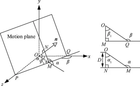
Fig.2 Location and orientation of motion plane.
What interests us most in this ellipsoid family of PROs includes the location and orientation of the resulting motion plane.According to the definitions in Eqs.(15)–(16), we can compute the two direction angels and the distance of the motion plane as follows:
which indicates that the pose triad of the motion plane where the ellipsoid family evolves can be represented by π(90°,arctan k,0).It can be easily checked that when k=0,the pose triad turns to, which represents a projected 2:1 elliptic PRO.When k=±√---3, the pose triad equals π(90°,±60°,0) , which is a circular PRO.It can be easily proved that for any PRO in the ellipsoid family, the motion plane is always perpendicular with xOz plane, which indicates that α=90°holds identically.The intersection angle between the motion plane and the xOy plane is β=arctan k.Besides,the motion plane of the relative orbit in the ellipsoid family also passes through the origin.The center of the ellipsoid family, however, is not the origin but C(0,q,0).The generation mechanism of the ellipsoid family and the resulting projected trajectories of the relative orbit are shown in Fig.3.According to Figs.3(a) and (b), the PRO is generated by cutting the spheroid with the motion plane that is determined by the initial states.It should be noted that the motion plane always passes through the origin.
3.3.Semi-axes and eccentricity
For simplicity, Eq.(11) can be transformed into the standard form as follows:
According to Eq.(18),it is known that the semi-axes of the ellipsoid are of lengths
Since the lengths of the two axes of this ellipsoid are the same, i.e., c1=c3, the corresponding figure is called a spheroid.Two special cases should be addressed here.If k=±√---3,there is c1=c2=c3=2A and the quadratic surface turns to a sphere, which corresponds to the case of circular PROs.If k=0, Eq.(11) will be degraded into Eq.(6), which corresponds to the case of 2:1 elliptic PROs.These two cases(k=±√---3and k=0) demonstrate that the ellipsoid family of PROs or k-family of PROs is a more general family of PROs.The semi-major and semi-minor axes can be computed by

Fig.3 Ellipsoid family of PROs and their motion planes.
Then the ratio between the semi-major and semi-minor axes can be parametrized by k as follows:

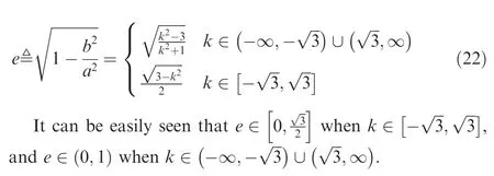
The eccentricity of the ellipse can be computed by
3.4.Maximal and minimal distances
In the design of relative orbits, metric quantification is as important as geometry determination.Here,metric quantification means how to compute the size (e.g., the maximal and minimal distances) of the relative orbits (see Fig.5).It should be noted that the‘‘distance”(d)here means the length from the origin to a point at a PRO.This is different with the definition of ‘‘distance” (D) of the motion plane because D is measured by the minimal length from the origin to the points at the motion plane.In the case of the 2:1 elliptic PROs,we have provided some formulas (see Eq.(13)) to determine the maximal and minimal distances from a satellite to the origin.In the case of the general ellipsoid family, we use the universal method to measure the extreme distances.
To this end, we firstly present the expression for the distance from a point to the origin at a PRO that evolves in an ellipsoid family as follows:

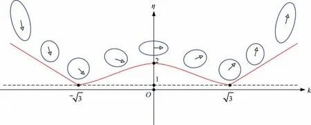
Fig.4 Evolution law of ratio η with respect to correlation coefficient k.

Fig.5 Maximal and minimal distances of PRO.

which corresponds to the family of circular PROs with a center C(0,q,0).When q=0 holds, the circular PRO encloses the origin, and the distance of the origin from any point of the PRO is a constant, i.e., 2A.When q≠0, which corresponds to the general case of circular PROs, the distance varies.The maximal and minimal distances are computed by evaluating the values of distance function at terminal points, i.e.,ymax=2A+q and ymin=-2A+q, which results in
As for the general case of ellipsoid family of PROs, i.e.,k≠±√---3, the squared distance is a quadratic equation.The distance extremum in the general case can be found by evaluating the values of d at the critical points and the terminal points of the quadratic equation.
It is known that the only extreme value point of the quadratic equation in this case is
which varies with the parameter k as shown in Fig.6,and can be summarized as

Fig.6 Evolution of extreme value point with respect to parameter k with q = 1.
The extremum of distance should be determined from three possible values: d(- 2A+q), d(2A+q), and d( ys) where
It can be seen that eight possible scenarios of the extremum for the squared distance function d2, which is a quadratic curve, are shown in Fig.7.Note that the parameter A is the amplitude of the relative motion and should be more than zero in all cases.When k2-3>0,the squared distance is a convex function,and the resulting parabola curve has an open mouth upward, e.g., Cases 1 – 4; otherwise, it is concave and the mouth is downward, e.g., Cases 5 – 8.
(1) Case 1
If Case 1 exists, then 2A+q ≤ysshould be firstly required with the premise of k2<3, which is equal to

Fig.7 Eight cases of extremum distribution for squared distance function.
On the other hand, d(2A+q)≤d( - 2A+q) is true only under the condition of q ≤0.Hence, Case 1 truly exists and the extremums of distance are
(2) Case 2
Firstly, d(2A+q)≤d(- 2A+q) is true if q ≤0 with the premise of k2<3.By imposing -2A+q ≤ys≤2A+q, we can easily conclude that the following condition should be satisfied:
Then,the maximal and minimal distances can be expressed as

Then, the maximal and minimal distances could be computed as follows:
(4) Case 4

The maximal and minimal distances are
(5) Case 5
If Case 5 exists,then 2A+q ≤ysshould be firstly required with the premise of k2>3, which equals
On the other hand, d(2A+q)≥d(- 2A+q) is true only under the condition of q ≥0.Hence, Case 5 truly exists and the extremums of distance are
(6) Case 6

Hence, the extremums of distance are
It is also easily examined that dmaxis real under the condition of k2>3.
(7) Case 7

Hence, the extremums of distance are
It is also easily examined that dmaxis real under the condition of k2>3.
(8) Case 8

Hence, the extremums of distance are
To summarize the dynamical mechanism of the new kind of PROs, we plot the distribution of ellipsoid family of PROs with different q-k pairs in Fig.8.At the left half plane, i.e.,q<0,Cases 1,2,7,and 8 are located.Cases 3,4,5 and 6,however, are positioned at the q-k right half plane.A PRO at the left half of the q-k plane has a center that is located at the negative along-track axis,in which we call the motion trajectory as left shift.A PRO at the q-k right half plane, however, has a positive bias at the along-track axis, in which we call the motion trajectory as right shift.There are two dashed lines at the k-q plane, i.e., k=√---3and k=-√---3, which represent the circular PRO family.It is clear that the maximal and minimal distance of circular PRO are the same.The horizontal axis q specifies a special family,i.e., the 2:1 elliptic PROs family.The vertical axis k determines the PROs family centered at the origin.More interestingly, the origin itself presents the 2:1 elliptic PRO centered at the origin.
4.Design method for on-orbit inspection
4.1.Problem description
We consider to apply the aforementioned models of PROs in the three-dimensional ellipsoid for the formation design of on-orbit service.It is assumed that one or multiple nano satellites fly around a target spacecraft to perform a close-range inspection (see Fig.9).The relative orbit should be designed to satisfy distance constraints and zenith pass constraint.The distance constraints are set to ensure safety and observability,for example,
where dsafeis the minimal distance for collision avoidance between the inspector and the target,and dobserveis the maximal distance for achieving the observation condition.The distances from the points of a candidate PRO to the origin should strictly satisfy the constraints shown in Eq.(45).
The zenith pass constraint is applied to optimize the observation angle since the camera of the inspector is always orientated to the origin.The view field of the camera is usually limited especially for a nano satellite.Therefore, the observable area of the target from the camera of the inspector is limited too.When the number of interested feature points is only one,there will be many satisfied PROs to be selected.When the number of interested feature points is more than 2,however,it may be hard to find a strictly satisfied PRO.It is assumed that the interested feature points are distributed almost in a same plane, named as the feature plane.In this case, how to determine a best PRO whose motion plane is close to the feature plane as much as possible is a problem worth studying.
4.2.Constraints and requirements
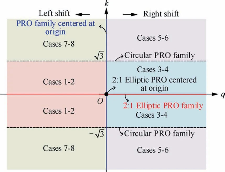
Fig.8 Distribution of PRO distance extremum in q-k parametric plane.

Fig.9 Close-range inspection of target by nano satellite formation in a PRO.
The best PRO is defined as that its motion plane can overlap with the feature plane to the maximum extent, that is, from a mathematical point of view, the angle between the normal vectors of the motion plane and the feature plane should be minimized.To find the best PRO, the angle θ, i.e., the angle between the two direction vectors nFand nM, should as small as possible.Here, the unit vectors nFand nMare the normal vectors perpendicular to the feature plane and the motion plane, respectively (see Fig.10).
It is noted that the feature points are the observed points at the feature plane, and the PRO lies at the motion plane.The feature plane is determined by the origin and all feature points through regression fit.It is assumed that the feature plane is represented by
where nF= [nF1,nF2,-1]T, and nF1, nF2and nF4are determined by solving the following equation:
where xi, yi, and zi(i = 1,2,...,N) are the relative position components of the feature points, and N is the number of the feature points.The normal vector of the motion plane is nM= [nM1,nM2,nM3]T, and nM1, nM2and nM3are determined by solving the following equation:
It is clear that the intersection angle between the feature plane and the motion plane, i.e., θ, can be expressed as

Fig.10 Relationship between feature plane and motion plane.
where nF3=-1.Hence, the best PRO is found by minimizing θ as follows:
If define a function G(k ) as follows:
Then the angle θ will be minimized or maximized when the derivative of G(k ) with respect to k is equal to zero, which results in
By substituting Eq.(52) into Eq.(50), we will find that k=nF1is the final solution for the minimized θ whose value is correspondingly
It is noticed from Eq.(53) that=0 cannot be achieved in most cases since≥0.When nF2=0, however,the feature plane and the motion plane will be coincident with each other.Once the correlation coefficient k is determined,the ratio between the maximal and minimal distances will be fixed too.It should be noted here that q = 0 is set as a premise to ensure that the center of the PRO is located at the origin.In case of q=0,the maximal and minimal distances can be computed as follows:
where A is the amplitude of the relative motion.Considering the constraint of distance shown in Eq.(50) and the extreme distances expressions shown in Eq.(54), it is required that
4.3.Design algorithm
According to the analysis above,a formation design algorithm is proposed for target tracking and inspection considering various requirements for collision avoidance and observable distance as follows:
Step 1.Input the orbital angular velocity n of the target,the collision avoidance distance dsafe, the furthest observable distance dobserve, and the expected observing feature points

Fig.11 Numerical verification of ellipsoid family of PROs.

Table 1 Parameters and corresponding maximal and minimal distances computed.

Step 7.Output the generated PRO by integrating the relative dynamics at the initial states computed above.

Fig.12 Numerical verification of maximal and minimal distances.
5.Numerical examples and analysis
In this section, the model and methods are evaluated and verified by numerical simulations.There are three main aspects that should be addressed.Firstly, the theory of PROs in the ellipsoid family are tested by examining whether the relative orbit trajectories lie at the surface of the theoretically predicted ellipsoid.Secondly, the formulas for computing the maximal and minimal distances in all eight cases are validated by comparing the results of theoretical prediction and numerical computation.Thirdly, the formation design method for on-orbit inspection mission is examined by some typical examples.

Fig.12 (continued)
5.1.Numerical verification of ellipsoid family of PROs
It is assumed that A = 10 km, q = 10 km, and φ = 0°.The correlation coefficient k is valued from-8 to 8 with an interval 2.Then, the resulting PROs corresponding to each set of parameters are generated by using Eq.(5).The correspondent ellipsoid in each case is also calculated by using Eq.(19).The PROs and related ellipsoids are plotted in the same figure, as shown in Fig.11.It can be seen that each PRO is perfectly inserted to the surface of the related ellipsoid.This indicates that the new discovery about the ellipsoid family of PROs is correct.Besides, the triad pose π( α,β,D)that is used to represent the location and orientation of the motion plane is also calculated from Eqs.(7)–(9).The results are summarized here:β(-8) = 7.125°, β(-6) = 9.462°, β(-4) = 14.036°, β(-2) = 26.565°, β(0) = 90.0°, β(2) = 153.435°, β(4) = 165.964°, β(6) = 170.538°, and β(8) = 172.875°.For all the cases, α = 90°, and D = 0.These results are well consistent with the numerical simulation of the related PRO trajectory.
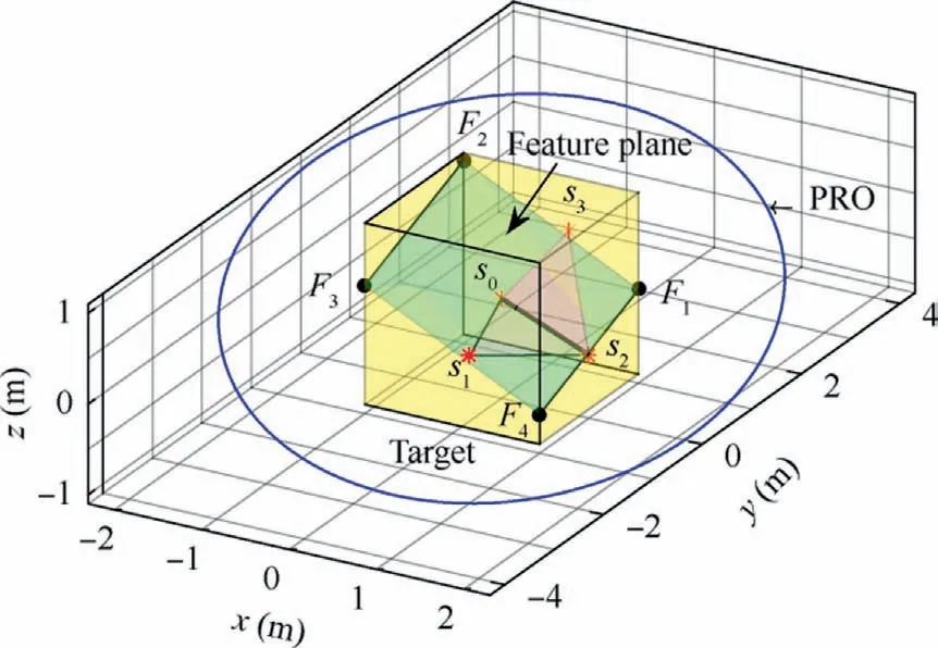
Fig.13 Design results of satisfied PRO in three-dimensional space.
5.2.Numerical verification of maximal and minimal distances
According to the theory in this paper, there are eight cases needed to be distinguished to select the proper formulas to compute the maximal and minimal distances of a PRO in the ellipsoid family from the origin.To verify this theory, we set the corresponding parameters for the eight different cases,i.e., k, q and A, as shown in Table 1.In all these cases, we assume that p = 0 for periodicity.Based on these conditions,the maximal and minimal distances are theoretically computed by using the formulas in Section 3.4, and are finally shown in Table 1.Then,the PRO trajectories with those parameters are further computed by using Eq.(5).The maximal and minimal distances from the points in a PRO to the origin are also numerically searched by evaluating the distance function.The computed trajectories are shown in Fig.12.The maximal and minimal distances are represented by blue dashed and green dotted lines, respectively.It is noted that the maximal or minimal distances possibly have two critical points.It is found that the theoretically predicted results are well consistent with the numerical results.This indicates that the methods here are basically correct.
5.3.Numerical verification of formation design method
It is assumed that a target satellite flies in a circular orbit with an altitude of 500 km, which leads to a mean orbital angular velocity n=0.0011.A nano satellite of 2 kg is required to perform a close-range inspection of the target.The collision avoidance distance is set as dsafe= 2 m, and the upper limit of the observable distance is set as dobserve= 5 m.The target satellite is a cube with an envelope of 1 m × 1 m × 1 m.The center of the target is at the origin with a coordinate of s0= [0, 0, 0]T.The feature points represent some key devices on the surface of the target.

Fig.14 Design results of satisfied PRO in xOz and xOy planes.
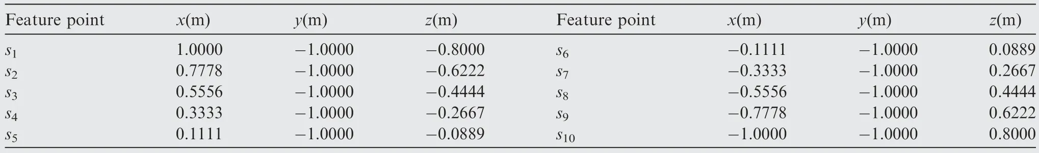
Table 2 Coordinates of coplanar feature points.

Fig.15 Design results of satisfied PRO when feature plane and motion plane coincide.

Table 3 Coordinates of the feature points distributed on two surfaces.

Fig.16 Distribution of twenty feature points.

Fig.17 Designed PRO and computed extreme distances.
5.3.1.Non-coplanar feature points
In the first case, we assume that there are three different feature points that are not distributed in the same plane.The coordinates of the feature points are set as s1= [0.2, -1,-0.2]T,s2=[1,0,-0.4]T,and s3=[0.2,1,0.4]T,with the unit being meter.According to the values assumed here, the components of the normal vector of the feature plane is computed by Eq.(52) as nF1= - 0.4915, nF2= 0.3, nF3= - 1, and nF4= 0.122.Hence, the correlation coefficient k= -0.4915.The minimal intersection angle θmin=15.07°.The bounds of the amplitude are computed as Amin=1.7949 m and Amax= 2.5 m, and a satisfied amplitude A = 2.1474 m.The initial states of relative motion with φ = 0 and q = 0 are then computed as x0= 2.1474 m, y0= 0 m,z0= -1.0555 m, vx0= 0 m/s, vy0= -0.0048 m/s, and vz0= 0 m/s.

Fig.18 Projections of feature points and the designed PRO.
Then, the computed PRO is propagated by using the relative motion equations, and the resulting trajectory is shown in Figs.13 and 14.The feature points are represented by the markers of red stars.The two planes generated by s0-s1-s2and s0-s2-s3are plotted in grey.It is clear that the four points of s0,s1,s2,and s3cannot be placed in a same plane.Therefore,the feature plane is actually the closest plane which has the minimal distance to all feature points.The feature plane in this case is shown by the green rectangle which intersects with the four edges of the target by four points such as F0, F1, F2, and F3,as shown in Fig.13.The two-dimensional projection of the relative orbit and the related surfaces are further shown in Fig.14.
It is seen that the projection of the PRO in the xOz plane is a line which passes through the feature points, but not all the feature points are exactly located at this line, which is consistent with the prediction.Moreover,it is also seen that the projection of the feature plane is not a line in the xOz plane,which indicates that the feature plane and the motion plane are not coincident.The computation based on Eq.(53) shows that the intersection angle between these two planes is actually 15.0687°.The projection of the PRO in the xOy plane shows that the minimal distance between the target and the PRO satisfies the collision avoidance requirement (dsafe= 2 m).The maximal distance between the target and the PRO also satisfies the observable condition (dobserve= 5 m).
5.3.2.Coplanar feature points
In the second case, we assume that there are ten different feature points that are located in the same plane.The coordinates of the feature points are set as in Table 2.According to the values assumed here,the components of the normal vector of the feature plane is computed by Eq.(52)as nF1= -0.8,nF2=0,nF3= - 1, and nF4= 0.Hence, the correlation coefficient k = - 0.8.The minimal intersection angle θmin= 0°, which indicates that the motion plane and the feature plane coincide.The bounds of the amplitude are computed as Amin=1.5617 m and Amax= 2.5 m, and a satisfied amplitude A = 2.0309 m.The initial states of relative motion with φ = 0 and q = 0 are then computed as x0= 2.0309 m, y0= 0 m,z0= - 1.6247 m, vx0= 0 m/s, vy0= - 0.0045 m/s, and vz0=0 m/s.Then,the computed PRO is propagated by using the relative motion equations, and the resulting trajectory is shown in Fig.15.The feature points are represented by the markers of red stars.It is seen from Fig.15(a)that the feature points are all in a line,and constitute a same plane with the origin.From Fig.15(b),we can see that the PRO and the feature plane coincide,and the projections lie in a same line.It is clear that the nano satellite can observe those feature points in a proper orientation (i.e., zenith pass) in this case.
5.3.3.Large size formation with multiple feature points
In the third case, we consider a large size formation for space target inspection.Different from that in Cases 1 and 2,the collision avoidance distance is increased to dsafe= 10 m, and the upper limit of the observable distance is set as doberve=50 m.The feature points are distributed randomly at two adjacent surfaces of the target with the coordinates as shown in Table 3 and Fig.16.Then, the normal vector of the feature plane is computed as nF1= - 0.4751, nF2= - 0.011, nF3= - 1,and nF4= - 0.0327.Hence, the correlation coefficient k = - 0.4751, and the minimal intersection angle θmin= 0.5703°.The bounds of the amplitude are computed as Amin= 25 m and Amax= 9.0324 m, and a satisfied amplitude A = 17.0162 m.The maximal and minimal distances from the PRO to the origin are dmax= 34.03 m and dmin= 18.83 m, respectively, as shown in Fig.17.The initial states of the relative motion with φ = 0 and q = 0 are then computed as x0= 17.0162 m, y0= 0 m, z0= - 8.0845 m,vx0= 0 m/s, vy0= - 0.0377 m/s, and vz0= 0 m/s.The projection of the propagated PRO and the distribution of the feature points in the xOz and xOy planes are shown Fig.18.It can be seen that the PRO closely passes through the feature points in a best way.These results demonstrate the validity of the design method for inspection formation with constraints.
6.Conclusions
The arbitrary elliptic periodic relative orbits are general ellipses with different eccentricities and tilts that can be uniquely characterized by the correlation coefficient.This kind of relative orbits is an extension to the general circular orbit,and the latter has been reported in other references.The main characteristics, such as the location and orientation of the motion plane, and the maximal and minimal distances, are analytically derived and detailly analyzed.It has been found that the extreme distances have rather complex distribution law, which has been summarized as eight different scenarios.The general elliptic orbits can be used for close-range target inspection by nano satellite formation.The formation design method considering safety and observability is then proposed based on the models and methods developed in this paper.The numerical examples well demonstrate the validity of the models and methods proposed.It is suggested that the other family of periodic relative orbits could be parametrized in a similar form in future.Other on-orbit service missions, such as on-orbit assembly, could be a consideration for the future study on applications of the models and methods proposed.
Declaration of Competing Interest
The authors declare that they have no known competing financial interests or personal relationships that could have appeared to influence the work reported in this paper.
Acknowledgements
This work was supported by the National Natural Science Foundation of China (No.12172288) and the National Key R&D Program of China (Nos.2021YFC2202601,2021YFC2202603).
 CHINESE JOURNAL OF AERONAUTICS2023年10期
- CHINESE JOURNAL OF AERONAUTICS的其它文章
- Experimental investigation of typical surface treatment effect on velocity fluctuations in turbulent flow around an airfoil
- Oscillation quenching and physical explanation on freeplay-based aeroelastic airfoil in transonic viscous flow
- Difference analysis in terahertz wave propagation in thermochemical nonequilibrium plasma sheath under different hypersonic vehicle shapes
- Flight control of a flying wing aircraft based on circulation control using synthetic jet actuators
- Bandgap formation and low-frequency structural vibration suppression for stiffened plate-type metastructure with general boundary conditions
- Geometrically compatible integrated design method for conformal rotor and nacelle of distributed propulsion tilt-wing UAV