
Experimental investigation on weak shock wave mitigation characteristics of flexible polyurethane foam and polyurea
2024-02-29 08:22ShiyuJiChengWngWenlongXuDongFngfngQi
Defence Technology 2024年1期
Shiyu Ji , Cheng Wng ,*, Wenlong Xu , Dong M , Fngfng Qi
a State Key Laboratory of Explosion Science and Technology, Beijing Institute of Technology, Beijing,100081, China
b Institute for Advanced Technology, Shandong University, Jinan, 250061, China
Keywords: Free-field explosion Weak shock wave mitigation Polyurea Polyurethane foam Multi-layered composites
ABSTRACT In recent years, explosion shock wave has been considered as a signature injury of the current military conflicts.Although strong shock wave is lethal to the human body, weak shock wave can cause many more lasting consequences.To investigate the protection ability and characteristics of flexible materials and structures under weak shock wave loading, the blast wave produced by TNT explosive is loaded on the polyurethane foam with the density of 200.0 kg/m3(F-200) and 400.0 kg/m3(F-400), polyurea with the density of 1100.0 kg/m3(P-1100) and structures composed of the two materials, which are intended for individual protection.Experimental results indicate that the shock wave is attenuated to weak pressure disturbance after interacting with the flexible materials which are not damaged.The shock wave protective capability of single-layer materials is dependent on their thickness, density and microscopic characteristics.The overpressure, maximum pressure rise rate and impulse of transmitted wave decrease exponentially with increase in sample thickness.For the same thickness, F-400 provides better protective capability than F-200 while P-1100 shows the best protective capability among the three materials.In this study, as the materials are not destroyed, F-200 with a thickness more than 10.0 mm,F-400 with a thickness more than 4.0 mm,and P-1100 with a thickness more than 1.0 mm can attenuate the overpressure amplitude more than 90.0%.Further, multi-layer flexible composites are designed.Different layer layouts of designed structures and layer thickness of the single-layer materials can affect the protective performance.Within the research range, the structure in which polyurea is placed on the impact side shows the optimal shock wave protective performance,and the thicknesses of polyurea and polyurethane foam are 1.0 mm and 4.0 mm respectively.The overpressure attenuation rate reached maximum value of 93.3%and impulse attenuation capacity of this structure are better than those of single-layer polyurea and polyurethane foam with higher areal density.
1.Introduction
According to statistics,explosive is the main factor of individual casualties in current military conflicts.Among military service members,blast injuries are most often related to their exposure to blast shock wave [1-3].Generally speaking, the overpressure of shock wave can cause death when it exceeds 1.0 MPa.However,weak shock wave below 300.0 kPa may not lead to immediate death but can cause bodily injuries such as tympanic membrane rupture and traumatic brain injury, leading to costly therapy expenses and life-long physiological effects [4-6].Therefore, protecting the human body from shock wave should not only pay attention to strong shock wave,but also focus on weak shock wave which can cause long-term pain.
For the past few years,many researches have been implemented to evaluate and improve the blast shock wave protective performance of various materials and structures [7-11].Polyurea and polymer foam have been widely used because of their excellent protecting effect and popular price [12-15].Most of the studies focused on the strong shock wave loading on the structures,which combined polyurea and polymer foam with other materials to explore the damage mode and the anti-explosion performance.Some scholars have considered the use of polyurea to enhance the blast protection of metallic structures.Amini et al.[16-18] assess the shock resistance of monolithic steel plates and steel-polyurea bilayer plates under the shock loading with a peak pressure of 80.0 MPa, which found the polyurea coating can substantially improve the blast resistance of steel plates.They explored the significance of the relative position of polyurea coating with respect to the loading side by observing the deformation and the failure modes and considered that blast resistance is improved when polyurea is sprayed onto the back face.Ackland et al.[19] further investigated the whether the application of polyurea-coated plates would be advantageous to incorporate into blast resistant design under the condition of considering the same areal density.Hou et al.[20]has more comprehensively assessed evaluated the effect of structural configuration on air blast resistance of polyureacoated composite steel plates, which four types plates with equivalent areal density were subjected to different blast loading.The structure of SP(the polyurea coating is placed on the rear side)and SPS (the polyurea coating is sandwiched by two steel face sheets)showed the better protective ability in this study.Based on the above reports, Li et al.[21] elucidate the influence of spraying area,thickness, interface condition, on the overall structural resistance of polyurea-coated steel plates under air blast loading.Polyurea was also frequently applied to concrete structure and has been proven to be effective in preventing fragments from breaking off the surface of the structure.For example, Liu et al.[22]studied the effects of polyurea coating on anti-explosion performance of reinforced concrete arches through explosion experiments with shock wave overpressure exceeding 1.0 MPa.Gu et al.[23]explored the full-field explosion responses of polyurea which were measured by the three-dimensional digital image correlation(DIC)technique and studied the reinforcement ability of polyurea for the fiber-reinforced cement board through field gas explosion tests.Some studies have explored the blast resistance of polyurethane foams under the strong pressure loading.Mazek et al.[24]considered the rigid polyurethane foam as a mitigation system to enhance sandwich steel structure against blast impact.They predicted the performance of integral structures with and without rigid polyurethane foam layers under blast effect using 3-D nonlinear finite element analysis.Andami et al.[25] further investigated the influence of thickness and density of the rigid polyurethane foam layer on the response behavior of sandwich panels under blast loads of approximately 5.0 MPa by numerical studies.
In recent years,as the blast injuries is concerned progressively,a few scholars begin to explore the protective performance of polyurea and polymer foam under shock wave below 1.0 MPa.Grujicic et al.[26] applied finite element simulation to investigate the shockwave generation, propagation, dispersion and transmission/reflection within polyurea and the adjoining material layers under the shock wave loading below 600.0 kPa.Sugiyama et al.[27]applied finite element simulation and molecular dynamics simulation methods to observe the differences of shock wave mitigation capability of the conventional foam and polyurea,combining with the analysis on their microstructure and mechanical response.Schimizze et al.[28] performed shock wave protection tests on expanded foam materials using shock tube to produce overpressure about 352.0 kPa.The results were consistently showed that most materials could attenuate the peak overpressure, and the density and acoustic impedance mismatch were shown to be the primary importance on the pressure attenuate effect.Gelfand et al.[29,30]generated weak shock waves through the shock tube to load the polyurethane foam inside the shock tube.They analyzed experimental data on the parameters of shock waves refracted at gas-foam and foam-gas interfaces and proposed pseudo-gas model.In addition, they found that the foam below the critical thickness can amplify the blast wave overpressure by experimental verification.Skews et al.[31-33] further studied the reflected waves that were produced from porous compressible foam attached to a rigid wall when impacted by a weak shock wave and verified the accuracy of the model which proposed by Gelfand.Meanwhile, they studied the mechanical process of the interaction between the shock wave and the foam material and revealed the dynamic characteristics of the reflection, transmission and propagation of the shock wave in the material.
Although there are many researches on the shock wave mitigation performance of polyurea and polymer foam, most of them focus on the strong shock wave load.However, there is a lack of research on the protective performance of the two materials under the actual weak blast shock wave below 300.0 kPa.Therefore, in this paper, weak shock wave generated by TNT explosive in free field environment was used to impact on the single-layer flexible materials with different density and thickness parameters and multi-layer composites.As the direct or primary blast effects are associated with changes in environmental pressure due to the occurrence of the air blast, and mammals are sensitive to the incident, reflected and overpressure, the rate of rise to peak overpressure after arrival of the blast wave (That is the pressure rising rate.)and the duration of the blast wave[34].So,in this paper the protective performance of the materials was evaluated by quantitatively analyzing the deformation mode, peak overpressure,maximum pressure rising rate and impulse.Based on the trend of shock wave attenuation of single layer, the multi-layer composites were designed,and the effect of layer thickness as well as layout on the shock mitigation performance was evaluated under weak shock wave.It is expected that the present work can provide guidelines for the application of flexible materials and structures in the weak shock protection system.
The outline of this paper is organized as follows: Samples preparation and characteristics of samples are introduced in Section 2, Experimental method and evaluation indicators of shock wave protective performance are presented in Section 3, Results and discussion are presented in Section 4,and finally,Conclusion is drawn in Section 5.
2.Material preparation
2.1.Single-layer polymer
In this paper, polyurethane foam (labeled F) and polyurea(labeled P) are chosen as the tested materials, and both materials are made as rectangular plates with a length of 260.0 mm and a width of 310.0 mm.The thicknesses of polyurethane foam are 1.0 mm, 2.0 mm, 3.0 mm, 4.0 mm, 5.0 mm, 8.0 mm, 10.0 mm,15.0 mm and 20.0 mm respectively, and their densities are 200.0 kg/m3and 400.0 kg/m3.The thicknesses of polyurea are 0.5 mm, 1.0 mm, 2.0 mm, 3.0 mm, 4.0 mm and 5.0 mm, and the density is 1100.0 kg/m3.The properties of the materials are listed in Table 1, and each sample is named according to the format as "label-density-thickness".
Polyurethane foam with different thicknesses are purchased from Zhongheng Co., LTD, Dongguan, China, as shown in Fig.1.These samples are chosen for their excellent mechanical properties and viscoelasticity, as well as their affordability and accessibility.The scanning electron microscope (SEM) result in the enlarged version of Fig.1 shows that most of the cell structures ofpolyurethane foam are closed, and equipped with thick cell wall.Component A reacted with component B according to 3:7 wt ratio to form polyurea(Fig.2).Two types of raw materials are used in this study: component A is WANNATE MDI-100L (Wanhua Chemical Group Co.,LTD,Yantai,China)and the component B is Versalink P-1000 (Zhang Jiagang Yarui Chemical CO., LTD, Dongguan, China).The polyurea prepared using this method takes these advantages of long cure time and arbitrary plasticity.The atomic force microscope(AFM)result of polyurea is shown in the enlarged view of Fig.2.The 2D phase image of polyurea displays a typical micro-segregated structure, where thread-like hard segment domains are distributed in the continuous soft matrix.The 3D phase image provides more direct visual evidence of two distinct phases, which the lighter and darker areas correspond to the hard segment domains and soft segment, respectively.
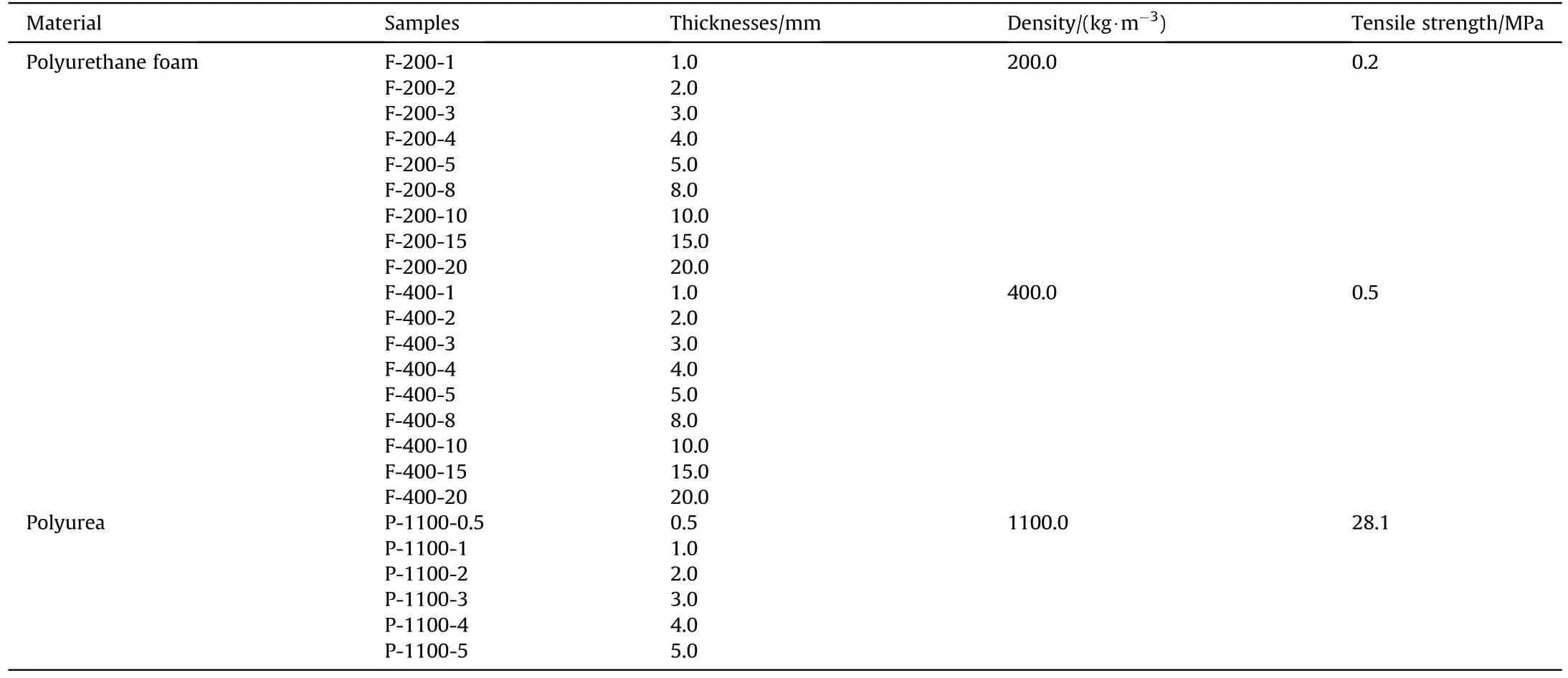
Table 1Types and parameters of single-layer polymer.
2.2.Multi-layered composites
The multi-layered composites are designed by combining the single-layer polyurea and polyurethane foam with the density of 400 kg/m3to explore the effect of layout and layer thickness on the protective performance.The multi-layered composites are classified into three groups according to the total thicknesses which include 2.0 mm, 3.0 mm and 5.0 mm.The layer thickness of polyurea remains unchanged(1.0 mm),and only the thicknesses of the polyurethane foam are changed (1.0 mm, 2.0 mm and 4.0 mm).Depending on the direction of blast loading, three types of structures are fabricated, i.e., P-F, F-P and P-F-P, as shown in Fig.3.The names P-F and F-P indicate that the polyurea is placed on the impact side and rear side of the structure.The polyurea layer is placed on both sides of the foam layer which is named P-F-P.The specific parameters are shown in Table 2.
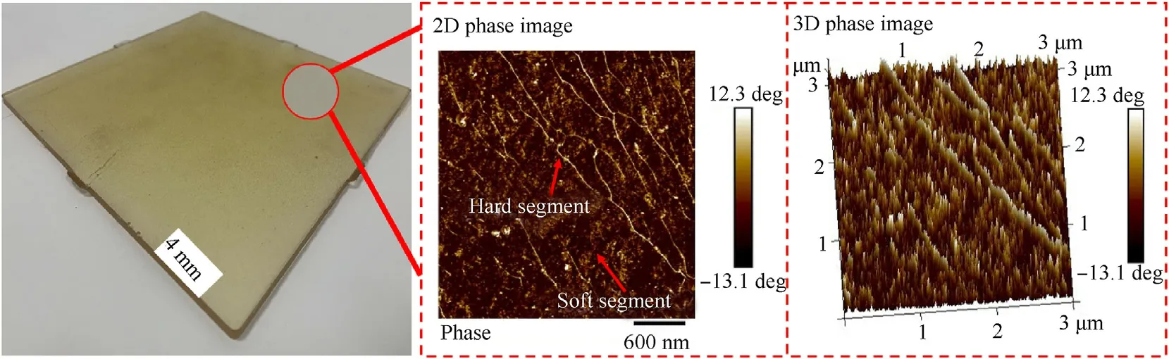
Fig.2.Macroscopic appearance of polyurea with the thickness of 4.0 mm, and its micro-segregated structure is shown in enlarged version.

Fig.3.Three designed structures of multi-layered composites.
3.Experimental methodology
3.1.Experimental setup
The experimental setups are illustrated in Fig.4(a).TNT explosive is used to produce shock wave loading, and the mass of explosive charge is 100.0 g.The ground condition is natural soil,and the explosive is suspended at a height of 1.5 m.The TNT explosive located at the center of the circle, and three equally spaced target plates are arranged in a circle with a radius of 1.2 m.The height of the target plate center is consistent with the height of the explosive.The size of each target plate is set to 0.6 m× 0.6 m,and the effective test area of each material is 0.23 m × 0.28 m.An anti-diffraction wave shielding box is installed on the back of the target plates,and the air pressure sensor is placed in the shielding box to exclude the interference of the diffractive wave.
Five air pressure sensors produced by Kistler company are arranged on circles centered on the explosive, and the model is 6233A0025(0-0.17 MPa).A data acquisition instrument of TraNET 408S with 16 channels is used to record the messages from air.As shown in Figs.4(b),1#,2#and 3#sensors are used to measure the transmitted wave overpressure behind the materials, and the distance from explosive center is 1.45 m.The 4# sensor is used to measure the incident shock wave overpressure, and located at 1.2 m from the explosive center.The 5#sensor is used to measure the free field shock wave overpressure, which has the same distance with the 1#, 2# and 3# sensors.
3.2.Evaluation indicators of shock wave mitigation performance
In this paper, the anti-explosion performance of materials is evaluated by three indicators, which include peak overpressure(the overpressure attenuation rate is also analyzed based on the peak overpressure), maximum pressure rise rate and impulse of shock wave.Peak overpressure is the maximum value of shock wave.Maximum pressure rise rate is defined as the maximum slope of the pressure vs.time signal.Impulse is the integral value under the pressure-time experimental curve [35,36].The attenuation rate of the peak overpressure mentioned above could be estimated according to the following equation
where φ is the attenuation rate of the peak overpressure (%),Piis the overpressure measured by the 5#sensor,Ptis the overpressure measured by the 1#, 2# and 3# sensors.
3.3.Stability verification of experimental results
In order to verify the stability of the experiment, the pressuretime curves of the 4# sensor in three repeated experiments are placed in Fig.5 for comparison.The 4# sensor is 1.2 m away from the explosive center, and it is used to measure the incident shock wave.As shown in Fig.5, in three repeated experiments, the peak overpressures measured by 4# sensor are 97.5 kPa, 97.1 kPa and 97.3 kPa, with a relative error of 0.2%, which indicate that the experimental system is stable.
4.Experimental results and discussion
4.1.Blast mitigation of single-layer polymer
4.1.1.Damagemodesofpolyurethanefoamandpressure-timecurve oftransmittedwave
When the shock wave loaded on the polyurethane foam with the density of 200.0 kg/m3, samples with thicknesses of 5.0 mm and below are damaged intensely along the edge of the constraint under this blast loading condition, as shown in Fig.6(a)-6(e).As the blast shock wave loaded on the impact side of the polyurethane foam, the polyurethane foam obtain the initial kinetic energy.Because the boundary of foam plates are fully clamped the plates occur bending deformation, and the mid-point deformation increases with impulse in this mode[37].In this phase,compressive stress wave is transmitted from the impact side to rear side, the foam core undergoes the compression and is changed into dense.While transverse shear reaction forces initiate from the clamped edges and propagate towards the middle of the structure.The two modes of failure may occur which include transverse shear fracture at the clamped boundary edges and tensile fracture at the center of the plates [38-40].When the pressure pulse amplitude is high enough, large inelastic deformation occurs.At higher impulse,thinning at the boundary eventually leads to partial or complete tearing, at which point the material reaches its ultimate strength[41].During this process, a part of the shock wave energy is dissipated through the polyurethane foam matrix itself, reflecting and refracting between the pores, while another part of the energy is expended by the deformation and destruction of the material[42].For samples with thicknesses equal or larger than 8.0 mm,localizedplastic deformation occurs at the center, and no failure appeared because of their higher ultimate strength, as depicted in Fig.6(f)and 6(g).At that time, the energy dissipation patterns of shock wave are mainly attribute to the damping of the matrix, reflection of shock wave by pore structure and the deformation of material.When the thickness of sample reaches 20.0 mm,the material only experiences elastic deformation under the shock wave loading(see Fig.6(h)).

Table 2Specific parameters of multi-layered composites.

Fig.4.Experimental setup: (a) Main view of testing ground; (b) Schematic diagram of top view.

Fig.5.The pressure-time curve of 4# sensor in three repeated experiments.
The transmitted pressure-time curve of these samples are shown in Fig.7 and the pressure-time curve of 5# sensor is listed for comparison.The pressure of 5# sensor is 68.7 kPa.The peak overpressure is attenuated below 51.1 kPa by samples with different thicknesses.What’s more,the transmitted overpressure of the samples has longer duration and smoother waveform.As shown in Fig.7(a), the undamaged samples F-200-1, F-200-2, F-200-3, F-200-4 and F-200-5 still include a relatively steep rising section and a falling section in the transmitted wave,however,the transmitted wave of the samples with the thickness equal or larger than 8.0 mm show a smooth rising section and falling section(Fig.7(b)).These results indicate that the undamaged materials can essentially transform the shock wave into a weak pressure disturbance and the characteristic with ultrashort rise time of typical shockwave action disappear [43].

Fig.6.Deformation and failure of polyurethane foam with the density of 200.0 kg/m3: (a) T = 1.0 mm; (b) T = 2.0 mm; (c) T = 3.0 mm; (d) T = 4.0 mm; (e) T = 5.0 mm; (f)T = 8.0 mm; (g) T = 15.0 mm; (h) T = 20.0 mm.
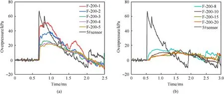
Fig.7.Transmitted pressure-time curve of polyurethane foam with the density of 200.0 kg/m3: (a) The samples with the thicknesses of 1.0 mm, 2.0 mm, 3.0 mm, 4.0 mm and 5.0 mm; (b) The samples with the thicknesses of 8.0 mm,10.0 mm,15.0 mm and 20.0 mm.
Fig.8 shows the deformation and failure of polyurethane foam with the density of 400.0 kg/m3.Obviously,the level of failure in F-400 is better than F-200 at the same thickness,which may be due to the strength difference of the materials.As shown in Fig.8(a)-8(c),the foam with the thickness of 1.0 mm is completely torn along the edge of the constraint.A tearing fractured area generates in the samples with the thickness of 2.0 mm and 3.0 mm, with radial cracks emerge in the fractured region.As shown in Fig.8(d)-8(f),the samples of F-400-4, F-400-5 and F-400-8 are strong enough and can remain relatively intact after impacted by the shockwave.These samples only exhibit plastic deformation, which show a slight bulge on the surface of samples.The samples with thickness of 10.0 mm and above, only elastic deformation occurs, with a restoration of the samples after the shock wave passed through them, as seen in Fig.8(g) and 8(h).
Fig.9 illustrates the transmitted wave of damaged materials(the thickness of 3.0 mm and below) still maintain the characters of shock wave which has the steep rising section,but the transmitted wave of undamaged materials (the thickness equal or larger than 4.0 mm) become smooth.The waveform of transmitted pressure follow the similar trend with F-200,that is the shape of waveform is related to the completeness of the materials.
4.1.2.Damagemodesofpolyureaandpressure-timecurveof transmittedwave
The deformation and failure of polyurea samples with different thicknesses are shown in Fig.10.The sample with a thickness of 0.5 mm (P-1100-0.5) has obvious tearing failure along the constrained boundary due to the large plastic deformation under the blast loading(see Fig.10(a)).Although there is no observed crack on the sample of P-1100-1(see Fig.10(b)),the surface of the sample is softened to form plastic deformation.When the material thicknesses reach or exceed 2.0 mm, no visible signs of failure and deformation are discovered after all the samples are carefully examined (see Fig.10(c)-10(f)).As depicted in Fig.11, the transmitted wave of the undamaged polyurea include a smooth rising section and a smooth falling section,indicating that the undamaged polyurea materials can also convert the shock wave into a weak pressure disturbance.

Fig.8.Deformation and failure of polyurethane foam with the density of 400.0 kg/m3: (a) T = 1.0 mm; (b) T = 2.0 mm; (c) T = 3.0 mm; (d) T = 4.0 mm; (e) T = 5.0 mm; (f)T = 8.0 mm; (g) T = 10.0 mm; (h) T = 15.0 mm.
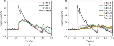
Fig.9.Transmitted pressure-time curve of polyurethane foam with the density of 400.0 kg/m3: (a) The samples with the thicknesses of 1.0 mm, 2.0 mm and 3.0 mm; (b) The samples with the thicknesses of 4.0 mm, 5.0 mm, 8.0 mm,10.0 mm,15.0 mm and 20.0 mm.
4.1.3.Shockwavemitigationperformanceofsingle-layerpolymer
Fig.12 shows the shock wave overpressure mitigation of singlelayer materials with varying thicknesses.Among the polyurethane foam with the density of 200.0 kg/m3,F-200-1 exhibits the highest transmitted overpressure of 51.1 kPa and overpressure attenuation rate of 26.8%.Meanwhile, F-200-20 shows the lowest transmitted overpressure of 5.0 kPa and overpressure attenuation rate of 92.8%.Regarding the polyurethane foam with the density of 400.0 kg/m3,F-400-1 has the highest transmitted overpressure of 28.2 kPa and overpressure attenuation rate of 59.4%, while F-400-20 has the lowest transmitted overpressure of 2.8 kPa and overpressure attenuation rate of 95.9%.As for the polyurea, P-1100-0.5 and P-1100-5 show the highest and lowest transmitted overpressure of 16.2 kPa and 2.1 kPa respectively, with overpressure attenuation rates are 76.4% and 96.9%.In general, as shown in Fig.12(a), the overpressures of the three materials show an exponential decreasing trend with the increase of thickness.It is consistent with the widely accepted shock wave attenuation model in homogeneous material[15].The attenuation of overpressure with thickness in the material indicates exponential decay according to relation which can be expressed as
wherexis the distance from the impact interface,α is the attenuation coefficient of the material,P0is initial pressure amplitude.
Except for the F-200 with thickness below 3.0 mm, the overpressure attenuation rate of all the tested samples exceed 50.0%(see Fig.12(b)).
Fig.10.Deformation and failure of polyurea with different thicknesses: (a)T = 0.5 mm; (b) T = 1.0 mm; (c) T = 2.0 mm; (d) T = 3.0 mm; (e) T = 4.0 mm; (f)T = 5.0 mm.
As the materials are not destroyed,F-200 with a thickness more than 10.0 mm, F-400 with a thickness more than 4.0 mm, and P-1100 with a thickness more than 1.0 mm can attenuate the overpressure amplitude more than 90.0%.F-200 and P-1100 with same thickness respectively show the worst and best overpressure attenuation efficiency among the three types of materials.When the thickness is 1.0 mm, the overpressure attenuation rate of P-1100-1 is increased by 57.3% compared with that of F-200-1, and when the thickness is 5.0 mm, it is increased by 26.4%.Table 3 presents the values of overpressure and overpressure attenuation rate of three materials.
Fig.12.Overpressure indicators of transmitted wave: (a) Overpressure of single-layer materials with different thicknesses; (b)Overpressure attenuation rate of single-layer materials with different thicknesses.
Fig.13 exhibits the maximum pressure rise rate of shock wave depending on different samples.The value of 5# sensor has the maximum value of 7471.5 kPa/ms.Compared with the damaged materials,the maximum pressure rise rate decrease suddenly when the samples are not damaged.This is because the transmitted wave of the torn samples mostly derived from the explosive source.But the transmitted wave of the undamaged materials has been transformed to weak pressure disturbance with smooth waveform by the materials, which resulting in a much lower maximum pressure rise rate than that of the torn materials.Moreover, with the increases of thickness,the maximum pressure rising rate of the three types samples tend to be consistent and it also can be seen that the maximum pressure rising rate of P-1100 is the lowest.Table 4 presents the values of maximum pressure rise rate of three materials.
The impulse values of the three samples are illustrated in Fig.14.The attenuation of impulse with thickness is consistent with that of pressure,which impulse values decrease with increase in thickness.For the polyurethane foam with the density of 200.0 kg/m3, the impulse value decreases from 37.7 to 13.0 kPa ms when the thickness changes from 1.0 to 20.0 mm.For the polyurethane foam with the density of 400.0 kg/m3,when the thickness changes from 1.0 to 20.0 mm,the impulse value decreases from 21.3 to 10.7 kPa ms.For the polyurea, the impulse value decrease from 14.3 to 11.4 kPa ms with the thickness increasing from 0.5 to 5.0 mm.Notably, the impulse attenuation performance of polyurea remains optimal among the three materials.Table 5 presents the values of impulse of three materials, the impulse of 5# sensor is 27.4 kPa ms, which is smaller than the value of F-200-1 and F-200-2.This is mainly due to the duration of the normal phase of the transmitted wave become longer for these two materials, but the overpressure values decrease insufficiently(see Table 3).
Fig.12.Overpressure indicators of transmitted wave: (a) Overpressure of single-layer materials with different thicknesses; (b) Overpressure attenuation rate of single-layer materials with different thicknesses.
Table 3Specific parameters of transmitted overpressure.
Overall, the shock wave protection capability of single-layer materials is related to their thickness, density and microscopic characteristics,as shown by the combined results of overpressure,maximum pressure rising rate and impulse.For the same material,the values of three evaluation indicators all decrease exponentially with increase in thickness, and the trend of overpressure value is most pronounced.For the same thickness,the protective capability of polyurethane foam with the density of 400.0 kg/m3is better than polyurethane foam with 200.0 kg/m3density, while polyurea shows the best protective capability among the three evaluation indicators.The superior shock wave mitigation behavior of polyurea may be related to its micro-phase segregated microstructure consisting of the so-called hard domains and a soft matrix.Previous reports have shown that atomic lateral motions and hydrogenbond breaking in the micro-phase segregated polyurea are main contributor to substantial energy absorption and dissipation [26].
4.2.Blast mitigation of multi-layered composites
When the shock wave propagates in the same medium, the shock energy will attenuate due to the damping property of the material itself.When the shock wave propagates from one medium to another with a different wave impedance, there will occur reflection and transmission at the interface [44].That is, the introduction of impedance-mismatch interface may be conducive to the improvement of the protection performance of materials with the same thickness.Therefore, the multi-layered structure which are composed of two types samples are designed to explore their shock wave protection capability, based on the requirements of lightweight of human body protective material.According to the test results of the single-layer materials, polyurea with the best protection performance and the polyurethane foam with the density of 400.0 kg/m3are chosen.
4.2.1.Damagemodesofmulti-layeredcompositesandpressuretimecurveoftransmittedwave
Under the weak blast loading, the integrity of multi-layered composites is maintained and no obvious break is observed.Fig.15 shows part of typical samples.There are no deformation and fracture occurred in P-F-(5)with the total thickness is 5.0 mm and the sample of P-F-(3) with 3.0 mm thickness occurs concave deformation.However, when the total thickness is reduced to 2.0 mm (P-F-(2)), debonding occurs between the foam layer and polyurea layer due to the impedance mismatch.At the interface between the foam and polyurea, the reflected tensile wave generates and induce spalling and even fragmentation of the material layer when the intensity of shockwaves is large enough [19].Decreasing the thickness of the foam layer within multi-layer structures will reduce the energy mitigation of shock wave and increase the intensity of reflected tensile wave at the interface,resulting in debonding.The sample of P-F-P-(2) shows the more serious debonding compared with P-F-(2) under the same total thickness.Transmitted overpressure of three groups of samples are shown in Fig.16.As shown in Fig.16(a)and 16(b), the transmitted wave of the samples with the total thickness of 2.0 mm and 3.0 mm include a steep rising section and a smooth falling section.But thesamples the total thickness of 5.0 mm exhibit the relatively smooth rising section as shown in Fig.16(c).

Table 4Specific parameters of maximum pressure rise rate.

Fig.14.Impulse indicator of the three materials.
4.2.2.Shockwavemitigationperformanceofmulti-layered composites
As is shown in Fig.17(a), the transmitted overpressure of three groups of multi-layered composites all decrease below 14.0 kPa,and the transmitted overpressure decrease with the total thicknesses of composites increase.When the total thickness is 3.0 mm,the structure of P-F-(3) and F-P-(3) show the lowest and highest transmitted overpressure of 9.2 kPa and 10.6 kPa respectively.The overpressure attenuation rate reach 86.6% and 84.5% (see Fig.17(b)), respectively.The samples with the total thickness of 5.0 mm show the same trend,which the overpressure attenuation rate of P-F-(5) and F-P-(5) reach 93.3% (the transmitted overpressure is 4.6 kPa) and 90.0% (the transmitted overpressure is 6.9 kPa).It’s indicated that the structures with polyurea at the front face exhibit the better pressure mitigation capability,which may be due to the wave impedance of polyurea is higher than that of polyurethane foam.Under the thicknesses of 3.0 mm and 5.0 mm,the overpressure attenuation rate of P-F-P is between P-F and F-P.It is confirmed that the increasing medium layers in the structure with the same thickness may not promote the overpressure resistance, unless the structure is reasonably arranged combining the theory of impedance matching.When the total thickness is 2.0 mm,the transmitted overpressure of P-F-(2),F-P-(2) and P-F-P-(2) is 11.2 kPa, 12.2 kPa and 13.3 kPa.The overpressure attenuation rate of P-F is still the highest (83.7%) but P-F-P shows the lowest (80.7%).
Table 5Specific parameters of impulse.
Fig.15.Deformation and failure of typical multi-layer samples: (a) P-F-(5); (b) P-F-(3); (c) P-F-(2); (d) P-F-P-(2).
As is shown in Fig.17(c), the maximum pressure rising rate of P-F is lowest in the samples with the total thickness of 2.0 mm and 5.0 mm.The maximum pressure rising rate don’t show good positive correlation with the increase of material thickness.The P-F shows the best impulse attenuation capability of the three group samples(see Fig.17(d)),and the impulse value still decrease with the increase of material thickness.However, the impulse values of F-P and P-F-P change irregularly with the thickness variation.The relevant data are shown in Table 6.
Combined with the three types of indicators, P-F-(5) has the optimal blast mitigation within the studied multi-layer composites.Compared with the F-400-8 with areal density of 3.2 kg/m2,F-200-15 with areal density of 3.0 kg/m2and P-1100-3 with areal density of 3.3 kg/m2,P-F-(5)with areal density of 2.7 kg/m2has the higher overpressure attenuation rate and lower impulse(the overpressure attenuation rate of P-F-(5), F-400-8, F-200-15 and P-1100-3 is 93.3%, 92.2%, 91.2% and 93.2%.the impulse of these samples is 9.9 kPa·ms, 13.6 kPa·ms, 14.7 kPa·ms and 13.2 kPa·ms, respectively).But the attenuation performance of maximum pressure rising rate of P-F-(5) does not show an obvious advantage contrasting with these three single-layer materials.Overall,the multilayer design has the potential to further enhance the protection capability.
5.Conclusions
In this paper,the weak shock wave generated by TNT explosive in an open free field environment is used to impact on the singlelayered polyurea and polyurethane foam.The blast-wave mitigation performance is analyzed according to overpressure,maximum pressure rising rate and impulse and combining with the deformation and failure of materials.Based on the single-layered materials with the better protection performance, the multi-layered composites are designed.The layout and thickness of the composites are further optimized.The main conclusions are as follows.
(1).For single-layered materials,F-400 with the thickness below 4.0 mm, F-200 with the thickness below 8.0 mm and the P-1100 with the thickness below 1.0 mm are damaged and the undamaged samples generated deformation in different degrees under the weak shock wave loading.After the shock wave interact with the undamaged samples,the shock wave is attenuated to be weak pressure disturbance with smooth rising and falling section.
Fig.16.Transmitted overpressure of multi-layered composites: (a) The samples with total thickness of 2.0 mm; (b) The samples with total thickness of 3.0 mm; (c) The samples with total thickness of 5.0 mm.
(2).The shock wave protection capability of single-layered materials is related to the thickness, density and microscopic properties of the material.The experimental results show that the overpressure, maximum pressure rising rate and impulse of transmitted wave decrease as exponential rule with increase in thickness for the same material.Under the same thickness, the protection capability of polyurethane foam with 400.0 kg/m3(F-400) density is better than polyurethane foam with 200.0 kg/m3density (F-200) while polyurea (P-1100) with show the best protection capability.In this study, when the materials are not destroyed, F-200 with a thickness more than 10.0 mm,F-400 with a thickness more than 4.0 mm, and P-1100 with a thickness more than 1.0 mm can attenuate the overpressure amplitude more than 90.0%.
Table 6Specific parameters of three evaluation indicators.
(3).The structures with polyurea on the front face shows the optimal shock wave protection capability of the three types of structures,and the type of P1-F4 has the best shock wave protection capability while maintains the integrity of the composite in this study.The overpressure attenuation rate reached maximum value of 93.3% and impulse attenuation capacity of P1-F4 is better than that of single-layer polyurea and polyurethane foam with the higher areal density.These results are important and meaningful for the structural designing of human body protection materials used to resistant weak shock wave.
Declaration of competing interest
The authors declare that they have no known competing financial interests or personal relationships that could have appeared to influence the work reported in this paper.
Acknowledgments
The research is supported by the National Natural Science Foundation of China (Grant Nos.12221002,12102233).

- Defence Technology的其它文章
- The interaction between a shaped charge jet and a single moving plate
- Machine learning for predicting the outcome of terminal ballistics events
- Fabrication and characterization of multi-scale coated boron powders with improved combustion performance: A brief review
- Experimental research on the launching system of auxiliary charge with filter cartridge structure
- Dependence of impact regime boundaries on the initial temperatures of projectiles and targets
- Experimental and numerical study of hypervelocity impact damage on composite overwrapped pressure vessels