
Al/Hf ratio-dependent mechanisms of microstructure and mechanical property of nearly fully dense Al-Hf reactive material
2024-02-29 08:22JunbaoLiWeibingLiXiaomingWang
Defence Technology 2024年1期
Junbao Li, Weibing Li, Xiaoming Wang
ZNDY of Ministerial Key Laboratory, Nanjing University of Science and Technology, Nanjing 210094, China
Keywords: Reactive material Particle size Split Hopkinson pressure bar test Stress-strain relationship Impact failure BP neural network
ABSTRACT This study proposed three types of Al-Hf reactive materials with particle size ratios (α), which were almost completely dense(porosity of <5.40%)owing to their preparation using hot-pressing technology.Microstructure characteristics and phase composition were analyzed, and the influence of particle size ratios on dynamic mechanical behavior and damage mechanism were investigated.The prepared sample with α=0.1 exhibited continuous wrapping of the Hf phase by the Al phase.Hf-Hf contact (continuous Hf phase) within the sample gradually increased with increasing α, and a small amount of fine Hf appeared for the sample with α = 1.The reactive materials exhibited clear strain-rate sensitivity, with flow stress σ0.05 and failure strain εf increasing approximately linearly with increasing strain rate ˙ε.It is found that the plastic deformation of the material increased with increasing strain rate.As α increased from 0.1 to 1,the flow stress gradually increased.Impact failure of the material was dominated by ductile fracture with a large Al phase plastic deformation band for lower α,while brittle fracture with crushed Hf particles occurred at higher α.Finally,a constitutive model based on BP neural network was proposed to describe the stress-strain relationships of the materials, with an average relative error of 2.22%.
1.Introduction
Reactive materials are a category of functional material that can exhibit structural strength and release energy through chemical reactions under sufficient mechanical, electrical, or laser stimulation.Reactive materials are generally made from metal-polymer[1-3], metal-metal oxide [4], and metal-metal [5-8] composites at the micron or nanoscale, using processing techniques such as cold-pressing-sintering,hot isostatic pressing(HIP),and explosion sintering,which can serve both as structural elements as well as a source of chemical energy released upon initiation [9].Common military applications of reactive materials include kinetic energy penetrators [10,11], reaction fragments [12], and warhead shells[13,14].
Previous studies on the enhancing effect of reactive materials showed that,compared with traditional metal liner shaped charge,a relative larger hole diameter accompanying with fragmentation effects of penetrating steel plates can be produced by reactive liner shaped charge [15,16].Zheng et al.[17] researched the explosioninduced formation and thermochemical response of PTFE/Al granular jet using mesoscale simulation method, and found that the inner wall of the reactive liner has a much higher reaction extent, due to a more significant temperature rise.To improve the penetration depths of reactive jets, a novel formulation system of PTFE/Al/Cu/Pb for reactive liner is proposed and studied by Guo[18].It was found that the proposed reactive jets penetrating steel targets could produce a deeper penetration depth and target rupture effect compared with the traditional PTFE/Al reactive jet.
Density and strength are two important factors in the design of reactive materials to meet the application requirements for structural components.The Naval Surface Warfare Center of the United States demonstrated the effectiveness of high-density reactive materials (HDRM) in improving the explosive power and damage efficiency of warheads in 2011 [19], which attracted attention to metal-metal-type reactive materials with densities up to 10 g/cm3and promoted the use of metals with high molecular mass and reactivity, such as Ta and Hf, in preparing HDRM [20].
Metal-metal reactive materials are difficult to prepare using traditional cold-pressing-hot-sintering processes.HIP and explosive sintering are effective methods for obtaining HDRM.Grudza et al.[21] prepared Al-Hf reactive materials with a compressive strength of 522 MPa and tensile strength of 397 MPa using HIP.Almost completely dense (density >98.0%) Al-Ni-Ta reactive materials were obtained by Zhou et al.[22] using explosive sintering.To avoid the high cost of HIP and unpredictable process outcomes of explosive sintering,Stamatis et al.[23]prepared Al-MoO3reactive materials with porosity less than 10.0% and excellent reaction performance using a hot-pressing method.
In general, the component properties and microstructures of reactive materials have a significant effect on their mechanical properties [24,25].For Al-M (M: Ni, Fe, Ta, W)-type formulations,the material is damaged in two main ways: interfacial spalling between the strengthening phase and the matrix phase, and local shear fracture of the matrix phase.The composition of the continuous phase and interfacial spalling between the continuous and dispersed phases are important factors that determine the mechanical strength and failure mode of reactive materials[11].For multiphase mixtures,components with higher content and smaller particle size tend to form continuous phases, while components with lower content and larger particle size exist in the dispersed state.To investigate the correlation between particle size and mechanical properties (strength toughness and deformation mechanism), Hu et al.compared the microstructures of two Al-Ni reactive materials with particle size ratios of 1 μm/25 μm and 20 μm/25 μm,and found that smaller Ni particles caused formation of a Ni continuous phase, while the material with larger Ni particles exhibited an Al continuous phase[26].In a study of the effect of W particle size on the mechanical behavior of polytetrafluoroethylene-Al-W reactive materials [27], deformation and fracture behavior of the material under dynamic loading were altered by microscopic force chains between small W particles.
The Al/Ni reactive materials were prepared by explosive consolidation in Ref.[28],and two kinds of samples,Ni continuous phase and Al continuous phase were obtained by designing the particle size.It showed that the sample with Ni continuous phase had higher quasi-static compressive strength of 325 MPa and fracture strain of 21.3%.Zhou et al.[29] also fabricated the fully dense Ni/Al reactive material by using explosive consolidation,which showed a high quasi-static compressive strength of 300 MPa and a ductility of 14.5%after heat-treatment.Response behavior of the PTFE/Al/W granular composite under different strain rates were investigated using quasi-static tests, the Hopkinson bar tests and the impact experiments[30].It was revealed that,only mechanical response was observed when the strain rate is less than 3.6 × 10³s-1, while the chemical reaction was found when the strain rate is higher than 4 × 10⁴s-1.
The component characteristics of reactive materials are important factors that affect the mechanical strength and failure modes.Using microstructure as a bridge to establish the intrinsic relationship between component characteristics and macroscopic mechanical properties is of great significance for the design and engineering application of high-performance reactive materials.This study investigated the effect of microstructure on the mechanical behavior and impact failure of Al-Hf reactive materials.Samples with three types of microstructure were prepared using hot pressing by changing the Al particle size.Microstructure characteristics, phase composition, and interfacial diffusion of the consolidated samples were analyzed using scanning electron microscopy (SEM), X-ray diffraction (XRD), and energy-dispersive spectroscopy (EDS).Split Hopkinson pressure bar (SHPB) experiments were carried out at strain rates of 900-3700 s-1.The effects of strain rate and particle size ratio on mechanical properties and damage modes are discussed.
2.Materials and methods
2.1.Material preparation
Almost completely compacted Al-Hf reactive material was prepared using a hot-pressing process.The molar ratio of Al and Hf powders was 56:44, and mixtures with three Al-Hf particle size ratios α were designed: Al: Hf = 1 μm: 10 μm, 6 μm: 10 μm, and 10 μm: 10 μm, which can be calculated using
wheredAl,dHfare the particle size of Al and Hf, respectively.
The Al and Hf powders(purity >99.9%)were provided by China Ordnance Industry 52nd Institute.The particle size distributions of the aluminum powders were observed using a MS2000MU laser particle size analyzer, as shown in Fig.1.The particle size distributions were relatively narrow, with median particle sizes of 1.46 μm, 6.15 μm, and 10.10 μm.For the 6 μm powder, more than 80.0%of particles were distributed between 4.23 μm and 10.60 μm.
The specific preparation process is shown in Fig.2.Al powders with different particle sizes, as observed by SEM (FEI Quanta 250FEG), exhibited spherical and uniform dispersion (Figs.2(a)-2(c)), while Hf powders presented an amorphous morphology(Fig.2(d)), with a particle size distribution between 1 μm and 50 μm.The scanning electron microscope has a secondary electrons(SE) image higher than 1.0 nm, and a backscattered electron (BSE)image higher than 2.5 nm at 30 kV under high vacuum mode.Some agglomeration occurred in the smaller Al powder, which can be explained by an increased van der Waals force between molecules caused by the larger specific surface area [31].The raw powders were weighed in a molar ratio of 56:44,mixed,and stirred on a ball mill (Fig.2(e)).The evenly stirred mixture(Fig.2(f)) was placed in an oven to dry for 24 h.The mixture was then poured into a designed mold according to the required mass, and the temperature history curves (Fig.2(g)) were set to prepare three Al-Hf samples (Fig.2(h)) using hot pressing.Samples with the required size for subsequent experiments were obtained by wire cutting (Fig.2(i)).
Fig.1.Particle size distributions of (a) 1 μm, (b) 6 μm, and (c) 10 μm aluminum powders.
Fig.2.Flow chart of sample preparation.
Strengths of the samples were measured using a universal testing machine, and the microstructure was analyzed by SEM.Phases were determined by XRD, and element distributions at a microscopic level were analyzed by EDS.Mechanical and physical properties of the materials are provided in Table 1.The porosity ranged from 3.17% to 5.40%, and the strength increased with increasing α.
2.2.Experimental methods
The Hopkinson bar technique is the main experimental method for studying the dynamic mechanical properties of materials under medium and high strain rate loading.Dynamic experiments were conducted on an SHPB apparatus, as shown in Fig.3, which consisted of a bullet,an incident bar,a transmission bar made of highstrength steel, and absorption devices.The bullet had a length of 200 mm and the lengths of the incident and transmission bars were 2000 mm.The bar diameter should be calculated such that thestress in the incident bar is less than 30%of the bar yield strength,which is [32].

Table 1Material properties.
whererbis the bar diameter,rsis the specimen diameter,σTis the specimen yield strength,σs,bis the bar yield strength.According to the calculation results, a diameter of 14.5 mm for the bar was selected.
Fig.3.Device layout of split Hopkinson pressure bar test.
During the test, both ends of the sample were coated with lubricating grease to reduce friction.Strain gauges attached to the incident and transmission bars recorded the history of the strain signal.A Wheatstone bridge connected to a strain gauge was used to transform the strain signal of the bars into a voltage signal,which was amplified by an ultra-dynamic resistance strain system and input into a data acquisition device, from which a voltage-time curve was output.The impact velocity of bullets was recorded using a laser velocimeter.The pearl cotton was used as energy absorbing device to avoid the damage of transmitted bar.A plastic box with open holes and Neoprene pasted around it was adopted as the soft recovery device for samples.
Experiments were carried out at designed strain rates of 900 s-1,1600 s-1, 2400 s-1, and 3700 s-1; each test condition was conducted twice.Based on the assumptions of one-dimensionality and uniformity, the stress-strain relationship was determined by Eqs.(3)-(5) [33].
where εr(t) and εt(t) are the reflected and transmitted strains,respectively.E,SB,andc0are Young's modulus,cross-sectional area,and longitudinal wave velocity of the bars, respectively;SSandLSare the cross-sectional area and length of the sample,respectively.
2.3.Microstructural characteristics
Fig.4 shows SEM backscattered electron images indicating the cross-sectional microstructure of the consolidated compacts(α = 0.1, 0.6, and 1).The darker phase is aluminum, owing to its lower atomic number, while the bright phase is hafnium.Distributions of the two phases were relatively uniform, and without obvious pores and cracks.Differences in microstructure characteristics of the samples were observed,which can be explained by the morphologies of the initial powders: for the α = 0.1 sample, less contact between Hf-Hf existed in the initial powders,leading to a morphology in which the Hf particles were surrounded by an Al continuous phase; for samples with larger Al particles, the Hf-Hf contact increased and these particles bound together during hot pressing,resulting in the appearance of a continuous Hf phase and a portion of small crushed Hf particles.
The formation mechanisms of the microstructures of these Al-Hf reactive materials with three particle size ratios are described in Fig.5.For the mixture with 1 μm Al, fluidity of the powder was low owing to large van der Waals forces between smaller particles; thus, Al particles uniformly aggregated around Hf, and densification of the mixture was achieved by filling the pores by plastic deformation of Al, ultimately forming an Al continuous phase.For the mixture with larger Al particles,fluidity of the powder was significantly improved and the dispersion of Al and Hf particles was more uniform.During the compression,some Al particles were unable to effectively fill the gaps between the Hf particles and were extruded, leading to the appearance of a Hf continuous phase.
Fig.5.Schematic diagram of the formation of microstructure for the three samples: (a) α = 0.1; (b) α = 0.6; (c) α = 1.
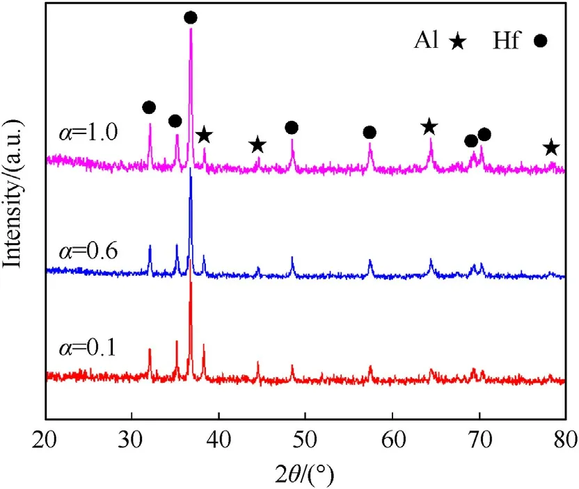
Fig.6.X-ray diffraction results of the three samples.
To ensure the reactivity of Al-Hf reactive materials in specific environments,it is necessary to prevent formation of intermetallic compounds during high-temperature and -pressure processing.XRD analysis was conducted for the three samples formed by hot pressing, as shown in Fig.6.Only peaks for Al and Hf phases occurred, indicating that no Al-Hf intermetallic were generated during preparation.
As shown in the microscopic images (Fig, 4), the Al-Hf contact interface was clear; therefore, element line scanning was performed on the interface using EDS(randomly select two zones),as shown in Fig.7,where the horizontal axis represents the scanning distance and the vertical axis represents the element intensity.A transition layer with a thickness of micrometers formed during the compaction.As the Al particle size increased, the thickness of the transition layer increased from approximately 1.7 μm-3 μm,which may be due to the greater number of interfaces and lower diffusion rates for samples with smaller Al particles.
3.Stress-strain relationships
3.1.Gauge trace analysis
The typical test curves shown in Fig.8 indicate that constant strain-rate loading was achieved during dynamic loading.The stress-time, strain rate-strain, and stress-strain relationships of replicate tests under the same designed strain rate are very close,revealing good repeatability of the results.
3.2.Effect of strain rate
Stress-strain relationships for the three samples at different strain rates are presented in Fig.9.These can be divided into elastic and plastic response stages.The stress pulse initially increased linearly and reflected a plastic deformation response after reaching the yield strength, then rapidly decreased when the material was damaged.The samples exhibited a certain strain rate effect,and the stresses under designed strain rates of 900-3700 s-1differed.At a strain value of 0.02 for the α=1 sample,the stress at a strain rate of 891 s-1was 436 MPa, which increased to 608 MPa at 3789 s-1,which was an increase of 39.5%and much greater than the value of 225 MPa measured under quasi-static loads.This is because the material bore most of the external load through the interaction of the Al and Hf phases under quasi-static loading, while Hf-Hf contact exhibited a strengthening effect by obstructing dislocation movement under dynamic loads: strengthening was more pronounced at higher strain rates.Other significant features of Fig.9 are that the samples exhibited strain-softening characteristics during the plastic stage and the failure strain increased with increasing strain rate.
To evaluate the mechanical properties at different strain rates,the flow stress σ0.05(stress at a strain of 0.05) and failure strain(strain when there is a rapid decline in the curve)were determined as presented in Table 2 and Fig.10.The values of σ0.05and failure strain increased linearly with increasing strain rate.Notably, the failure strains of the three samples were very similar, indicating that the material failure was barely influenced by its inherent microstructure.The flow stress-strain rate and failure strain-strain rate relationships were further fitted by a linear equation of the formy=a+bx:the fitting coefficients are listed in Table 3.
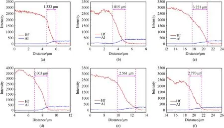
Fig.7.Linear scanning energy-dispersive spectroscopy images of the three samples:(a)α=0.1,zone 1;(b)α=0.6,zone 1;(c)α=1,zone 1;(d)α=0.1,zone 2;(e)α=0.6,zone 2;(f) α = 1, zone 2.

Fig.8.Typical curves measured for α = 1 sample: (a) Original signal; (b) Stress history curve; (c) Strain-rate history curve; (d) Stress-strain relationship.

Fig.9.Measured stress-strain curves under different strain rates: (a) α = 0.1; (b) α = 0.6; (c) α = 1.
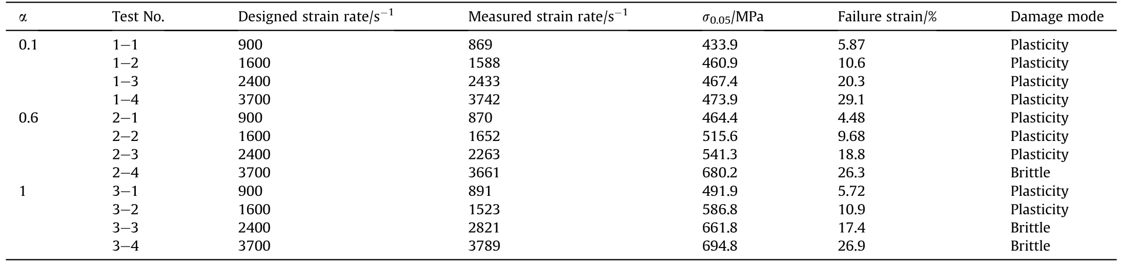
Table 2Results for split Hopkinson pressure bar tests.

Fig.10.(a) σ0.05 and (b) failure strain under different strain rates.
3.3.Effect of Al particle size
In addition to strain rate, the particle size ratio between components is a significant factor affecting the mechanical properties of Al-Hf reactive materials.Comparison of the stress-strain curves for the three samples,shown in Fig.11,indicates that the flow stress σ0.05increased and failure strain decreased with increasing particle size of Al, and the softening phenomenon became more obvious.
Mechanical properties of Al-Hf reactive materials are believed to be related to the microstructure and phase binding (Hf-Hf,Hf-Al).For the α=0.1 sample,Hf particles were well encapsulated by the Al continuous phase, resulting in a lower value of σ0.05because the overall mechanical properties of multiphase compacts depend on the continuous phase[11].For the α=1 sample,which exhibited some Hf continuous phase, the Hf particles could not be fully encapsulated by the Al phase owing to increased Hf-Hf contact, and Hf may withstand the main external impact load,which further explains the higher compressive strength of this sample.In contrast, the inherent brittleness of Hf and weak bonding force between Hf-Hf particles also resulted in the overall low plasticity of the α = 1 sample.

Table 3Fitting coefficients related to σ0.05 and failure strain.

Fig.11.Stress-strain relationships for the three samples under designed strain rates of (a) 900 and (b) 3700 s-1.
It should be noted that, the powders with relatively small particle sizes tend to clustered due in part to the large increases of the surface area, which enhance the effect of the van der Waals attraction forces.The uniformity of the compact may be reduced when it is fully compacted, resulting in insufficient resistance to external loading during deformation.On the other hand, it is believed that the systems with lower Gibbs free energy exhibit better stability at a certain temperature and pressure.For sample with smaller particles (large surface Gibbs free energy),deformation is more likely to occur under the same compressive load.
From the perspective of material deformation process as expressed in Fig.12, the distribution of Hf particles in the matrix phase for α = 0.1 sample was more uniform, therefore the coordinated deformation ability and ductility of the material was enhanced.For α = 1 sample, the dislocation accumulation will increase due to the lack of the additional slip between phases to release stress, which explained the improvement in material strength.

Fig.12.Schematic diagram of fracture process of α = 0.1 and α = 1 samples.
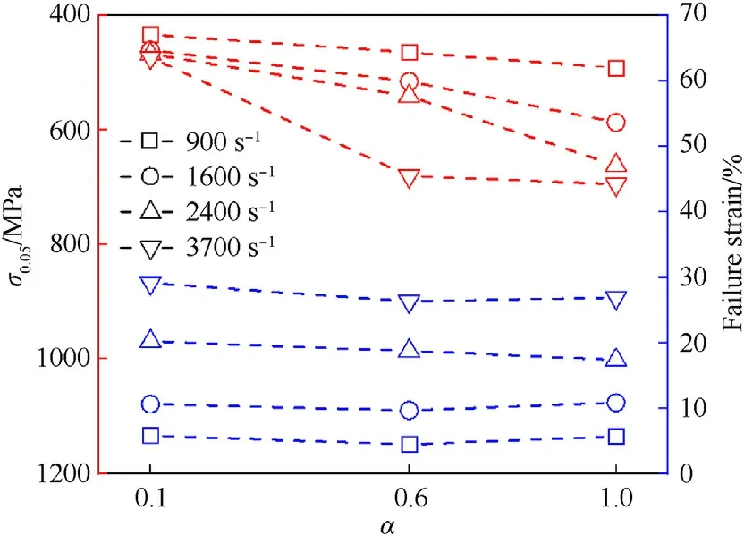
Fig.13.Values of σ0.05 and failure strain of the three samples.
Fig.13 shows that the values of σ0.05gradually decreased with increasing Al particle size, while the failure strain for the three samples hardly changed.As observed in the microstructure in Fig.4,more Hf-Hf contacts existed in samples with larger particle sizes of Al,which caused Hf to withstand the main external load at high strain rates,thereby significantly improving the value of σ0.05.Failure of materials is an accumulative process.The phase distribution gradually tends to a consistent condition as the strain increases to a high value;therefore,the failure strains for the samples were very similar.
4.Failure morphology and damage mechanism
Recoveries of the three samples at the design strain rates of 900 s-1and 3700 s-1are presented in Fig.14.The α = 0.1 sample remained intact after impact owing to its good toughness,while the samples with α values of 0.6 and 1 exhibited a certain collapse and cracks propagated along the surface at high strain rates, reflecting brittle fracture characteristics.The latter phenomenon may be due to weak interfacial bonding between Hf and larger Al particles.Failure modes of each sample are given in Table 2.
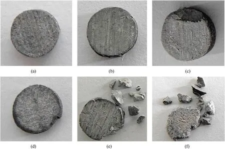
Fig.14.Recoveries of the three samples under designed strain rates of 900 and 3700 s-1: (a)α = 0.1, ˙εD = 900 s-1; (b)α = 0.6, ˙εD = 900 s-1; (c)α = 1, ˙εD = 900 s-1; (d)α = 0.1,˙εD = 3700 s-1; (e) α = 0.6, ˙εD = 3700 s-1; (f) α = 1, ˙εD = 3700 s-1.
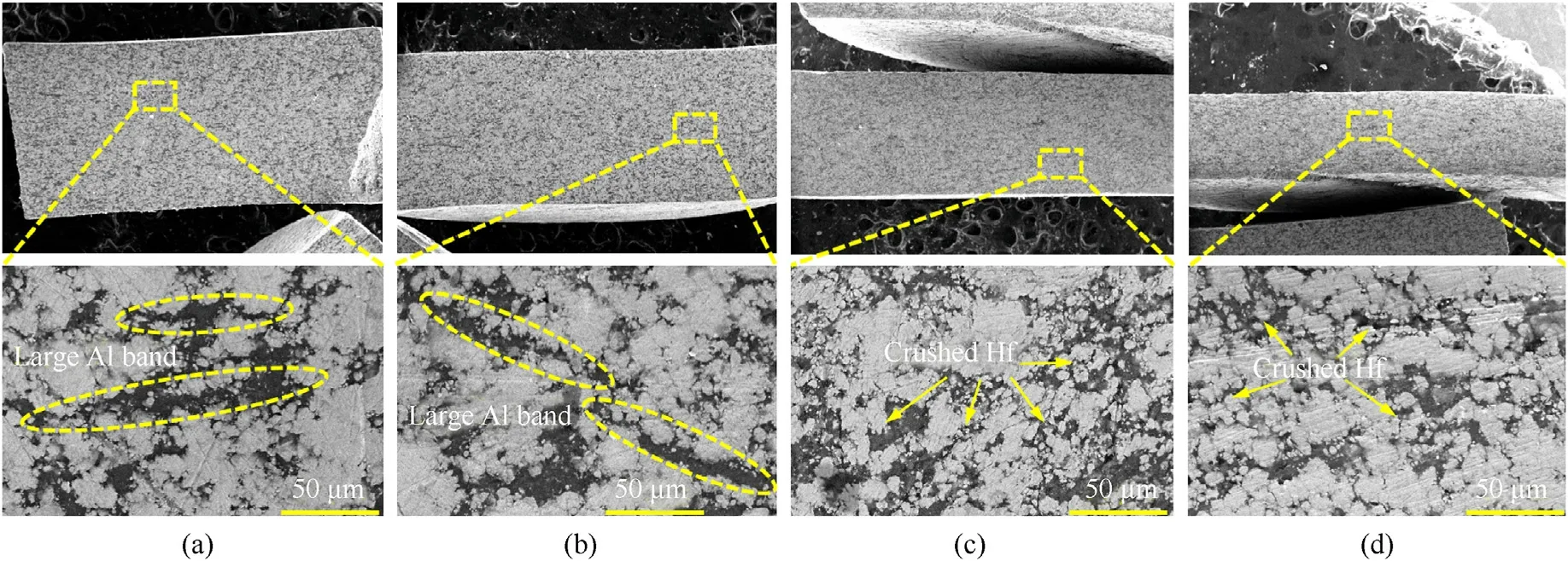
Fig.15.Microstructure of α = 1 recovered sample at different strain rates: (a) ˙ε = 891 s-1; (b) ˙ε = 1523 s-1; (c) ˙ε = 2821 s-1; (d) ˙ε = 3789 s-1.
Fig.15 shows the cross-section microstructure of the recovered α=1 sample after wire cutting.It is clear that plastic deformation increased with increasing strain rate.Many large continuous deformation bands of Al and Hf aggregation were observed at strain rates of 891 s-1and 1523 s-1,while numerous crushed Hf particles appeared at higher strain rates,which can be explained by the fact that the Hf phase mainly bore external loads through interaction under higher impact velocity.Microscopic comparison of the α=0.1 and α=1 samples in Fig.16 shows that the Al deformation bands for the material with smaller Al particles were small in area and large in number, which is related to isolated Hf particles uniformly surrounded by the Al continuous phase.This excellent coordinated deformation ability avoided the occurrence of Al deformation bands even at higher compressive strains.
Fig.17 presents the damage morphology of the recovered samples.It is clear that the dimples and Hf particles on the fracture surface were visible.The α = 1 sample exhibited larger crack with obvious propagation paths, while the sample with 1 μm Al presented more dispersed small cracks.
5.BP neural network constitutive relationships
To better describe the stress-strain relationships of Al-Hf reactive material with different particle size ratios, the Back Propagation (BP) [34] was introduced based on the experimental data.To improve training accuracy and shorten training time, a dual hidden layer network structure as shown in Fig.18 was adopted,which includes input layer,dual hidden layer,and output layer.The number of input layer (strain, strain rate, and particle size ratio)nodes is 3,the number of output layer(flow stress)nodes is 1.The number of nodes in the first hidden layer was determine as 40 using optimal formula[35],and the trial and error method[36]was used to determine the number of nodes in the second hidden layer as 30.
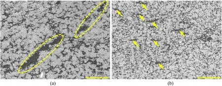
Fig.16.Comparison of cross-section microstructures of (a) α = 0.1 and (b) α = 1 recovered samples.

Fig.17.Comparison of fracture morphology of α = 0.1 and α = 1 recovered samples.

Fig.18.Schematic diagram of BP neural network.
As is presented in Fig.19, the specific training steps were as follows:
(a) Assigning network weights and initial threshold values.
(b) Calculating the inputs and outputs of each layer.
(c) Calculating the square error between the expected output and actual output.
(d) Determining the weight correction between nodeiand nodej.
(e) Repeating steps (b) to (d), and continuously correct the weight and threshold until the Mean squared error was less than 1 × 10⁻¹⁰.

Fig.19.Flow chart of calculating flow stress of Al-Hf reactive material by BP algorithm.
Based on the untrained data of samples(designed strain rates of 900 s-1-3600 s-1, particle size ratios of 0.1-1), the constitutive relationships were established using BP neural network, with a relative error as follow:
whereCis the actual value,Tis the predicted value,Nis the number of data points.
Calculation results showed that, the mean square error of the model decreased with the increase of iteration number during the training.The neural network achieved the optimal validation set performance when iterating to 423 steps.In addition, the error curve decreased smoothly during the iteration, indicating stable convergence of the training process.
Fig.20 shows the comparison between the experimental and predicted values of flow stress of the three reactive materials.It can be seen that the trend of the predicted flow stresses were basically consistent with the experimental values.The comparison results presented in Fig.21 showed that 96.8% of the BP predicted points were within a deviation of 10.0%,and the average relative error was 2.22%,revealing the model can reasonably predict the stress-strain history of Al-Hf reactive materials.

Fig.20.Comparisions between experimental and BP predicted values of flow stress at different strain rates: (a) ˙εD = 900 s-1; (b) ˙εD = 3700 s-1.
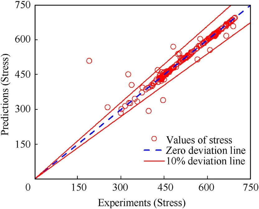
Fig.21.Comparisions between experimental and BP predicted values of flow stress for Al-Hf reactive materials.
6.Conclusions
Three almost fully dense Al-Hf reactive materials with particle size ratios of 1:10, 6:10, and 10:10 were prepared using hotpressing technology.The influence of particle size on dynamic mechanical behavior and failure mode was analyzed based on the microstructure,phase composition,and phase diffusion within the material.A constitutive model based on BP neural network was then established to describe the stress-strain relationships of the materials.The main conclusions are as follows:
(1) Microstructures of the materials were significantly affected by Al-Hf particle size ratio.Al existed as a continuous phase that uniformly enveloped isolated Hf particles for the α=0.1 sample.As α increased to 1, Al continuous phases were gradually replaced by Hf continuous phases and finely fragmented Hf appeared owing to an increase in Hf-Hf contacts.
(2) The material exhibited an apparent strain rate effect: flow stress σ0.05and failure strain increased linearly with increasing strain rate.The relationship between failure strain and strain rate was fitted as εf= 0.0007-1.289 ˙ε.
(3) The Al-Hf particle size ratio had a significant effect on the mechanical properties of the material.Flow stress improved and failure strain decreased with increasing Al particle size,which is because the Hf phase bore the main external load for samples with larger Al particles, resulting in higher compressive strength and lower plasticity.
(4) Microscopic observation of recovered samples showed that many Al deformation bands with a large area were generated within the material for lower strain rate and α.The material changed from brittle failure to more ductile failure with increasing strain rate and α, which is related to the increase of Hf-Hf contacts and the presence of crushed Al particles.
(5) The constitutive model of Al-Hf reactive material were established based on BP neural network, with an average relative error of 2.22%,and the data points with a prediction value deviation of less than 10.0% reach 96.8%, which can meet the needs of current engineering applications.
Declaration of competing interest
The authors declare that they have no known competing financial interests or personal relationships that could have appeared to influence the work reported in this paper.
Acknowledgments
The work presented in this paper has been funded by the National Natural Science Foundation of China (Grant No.12302437);China Postdoctoral Science Foundation (Grant No.2021M701710)

- Defence Technology的其它文章
- The interaction between a shaped charge jet and a single moving plate
- Machine learning for predicting the outcome of terminal ballistics events
- Fabrication and characterization of multi-scale coated boron powders with improved combustion performance: A brief review
- Experimental research on the launching system of auxiliary charge with filter cartridge structure
- Dependence of impact regime boundaries on the initial temperatures of projectiles and targets
- Experimental and numerical study of hypervelocity impact damage on composite overwrapped pressure vessels