
Experimental and numerical analyses of the effect of fibre content on the close-in blast performance of a UHPFRC beam
2024-02-29 08:22JunboYnQiyueZhngYnLiuYinglingXuZhenqingShiFnBiFengleiHung
Defence Technology 2024年1期
Junbo Yn , Qiyue Zhng , Yn Liu ,b,**, Yingling Xu , Zhenqing Shi , Fn Bi ,Fenglei Hung
a State Key Laboratory of Explosion Science and Technology, Beijing Institute of Technology, Beijing 100081, China
b Beijing Institute of Technology Chongqing Innovation Center, Chongqing 401120, China
Keywords: Blast performance Close-in blast Fiber content Mesoscale approach UHPFRC beams
ABSTRACT Limited research has been conducted on the influences of fiber content on close-in blasting characteristics for ultrahigh-performance fiber-reinforced concrete (UHPFRC) beams.This paper aims to address this knowledge gap through experimental and mesoscale numerical methods.Experiments were conducted on ten UHPFRC beams built with varying steel fiber volumetric fractions subjected to close-in explosive conditions.Additionally, this study considered other parameters, such as the longitudinal reinforcement type and ratio.In the case of UHPFRC beams featuring normal-strength longitudinal reinforcement of diameters Φ12,Φ16,and Φ20,a reduction in maximum displacement by magnitudes of 19.6%, 19.5%, and 17.4% was observed, respectively, as the volumetric fractions of fiber increased from 1.0% to 2.5%.In addition, increasing the longitudinal reinforcement ratio and using high-strength steel longitudinal reinforcement both significantly reduced the deformation characteristics and increase the blasting resistances of UHPFRC beams.However, the effects on the local crushing and spalling damage were not significant.A mesoscale finite element model,which considers the impacts of fiber parameters on UHPFRC beam behaviors, was also established and well correlated with the test findings.Nevertheless, parametric analyses were further conducted to examine the impacts of the steel fiber content and length and the hybrid effects of various types of microfibers and steel fibers on the blasting performance of UHPFRC beams.
1.Introduction
The frequency of explosive-induced occurrences, arising from both intentional detonations and inadvertent explosions, has demonstrated a noteworthy escalation on a global scale.Consequently, there emerges a pressing imperative to identify novel materials that can effectively enhance the blast resilience of reinforced concrete (RC) infrastructures when subjected to severe detonations [1-5].Ultrahigh-performance fiber-reinforced concrete (UHPFRC) typically comprises substantial quantities of Portland cement, silica fume (SF), and fine aggregates.The material is further reinforced with fibers and contains high concentrations of superplasticizer to achieve satisfactory fluidity while maintaining a significantly reduced water-to-binder ratio [6].The exceptional performance characteristics of UHPFRC, including its capacity for strain hardening, ultrahigh compressive strength of 150 MPa, and tensile strength of 10 MPa, render it a promising material for the construction of critical infrastructure that suffers explosive loads.UHPFRC has more flexural strength and toughness than normalstrength concrete (NSC) due to the stress transfer along the matrix to the fibers,the ability of fibers to bridge cracked exteriors,and the resistance of the concrete to crack initiation and spalling damage[7-10].The fiber content[11-15],shape[11,12,16-18]and type [19-22] have been demonstrated to affect the mechanical properties of UHPFRC.The assessment of the impact of fibers on blast characteristics is crucial in enhancing the resilience of UHPFRC structures against severe explosions.
The effectiveness of UHPFRC structures undergoing blasting loads was the focus of many studies.Li et al.investigated the dynamic properties of UHPFRC slabs under close-range blasting loads[7] and contact explosions [23] using computational and experimental methods.Their findings demonstrated that UHPFRC slabs exhibited blast loading behaviors superior to those of NSC slabs.Additionally,UHPFRC columns were subjected to explosion testing[24].The accompanying test findings demonstrated that UHPFRC columns had exceptional blast resistance properties,with minimal midspan deflection and concrete damage.Moreover,after blasting,UHPFRC columns were subjected to static axial loading tests.A high-strength concrete(HSC)column maintained 40%of its loading capacity following a blast of 8 kg of trinitrotoluene (TNT) at a similar standoff distance,whereas over 70%of the UHPFRC loading capacity was maintained following a burst of 35 kg of TNT at a 1.5 m standoff distance.Zhang et al.[25] empirically examined the blast efficiencies of concrete-filled double-skin steel tube (CFDST) columns.CFDSTs filled with UHPFRC could resist steel buckling and concrete crushing better than that filled with NSC, leading to a generalized global flexural reaction instead of localized structural failure.Wu et al.[26], Xu [27] and Su [28] experimentally and mathematically evaluated the near-field blasting efficiencies of ultrahigh-performance cementitious composite-filled steel tubes(UHPCC-FSTs).This finding demonstrated that local damage and global deformation characteristics were caused by close-range explosions, validating the advantage of UHPCC-FSTs relative to explosions in the adjacent field.Three techniques were used to examine the dynamic reactions of all the samples collected: velocity loading, equivalent single degree of freedom,and numerical simulations based on the arbitrary Lagrangian-Eulerian (ALE) elements method.The velocity approach included correlating experimental data and considering accuracy and computing performance.Yan et al.[29] analyzed the blast resistance of UHPFRC beams constructed from glass fiber-reinforced polymer(GFRP)bars.Relative to UHPFRC beams made with regular strength rebar,the longitudinal tensile rebar of GFRP increased the blasting endurance levels of UHPFRC beams.As the longitudinal reinforcement yield strength increased, the maximal displacements for comparable blast loading decreased.The GFRP-reinforced UHPFRC beams displayed self-centering performance,allowing these beams to return to their original location and thus producing a substantial rebound deflection and very small residual displacement.
In addition, the prediction of blast responses in UHPFRC structures became increasingly dependent on numerical methods.Su et al.[9] calibrated the Karagozian and Case concrete(KCC) model depicting the strength surface, equation of state (EOS), damage evolution, and strain rate effect characteristics of UHPFRC specimens.By utilizing this model, improved numerical simulations could accurately describe the dynamic responses of one-way simply supported reinforcements under medium-range explosions.Yang et al.[30]formed a new constitutive model for UHPFRC during blast loading.A new tensile damage model considering fiber bridging mechanisms was integrated into the Kong-Fang model.A comparison with experimental data revealed the enhanced behavior of this modified material model that was used to study UHPFRC under explosion loads.Additionally, mesoscale modeling was adopted in many numerical studies to consider the effects of fibers in UHPFRC.In this numerical model,UHPFRC was considered a composite material by Lee et al.[30],since this material could be divided into several components: mortar, polyethylene and steel fibers.The mesoscale model can accurately predict the blast and impact experimental results.A mesoscale numerical model for UHPFRC was developed by Zhang et al.[31], considering the random distribution, volumetric ratio, and bonding and sliding implications of fibers.This anticipated numerical model could better estimate the dynamic responses of UHPFRC structures than the macroscale homogenous approach under aircraft impact.Ellis et al.[31] applied a hierarchical multiscale modeling approach for simulating the blast behavior of UHPFRC through two scales: the multiple fiber length scale(MFLS)and structural length scale(SLS).The UHPFRC matrix fracture and subsequent fiber pull-out performance characteristics were simulated using the smallest length scale:MFLS.To investigate the overall scenario,the behavior of the UHPFRC panel was simulated using data from the MFLS,which was the coarsest length scale.The multiscale model was proven to enable the design of UHPFRC textiles that are greatly beneficial for blast load resistance.
The investigation of the influence of concrete strength on the blast performance of concrete structures has been a subject of extensive inquiry over a considerable period of time [1].For NSC and HSC [32], the impacts of concrete strength on their blasting behaviors are extensive.For UHPFRC,the influence of the concrete strength can be investigated by varying the fiber ratios.Some studies focused on its static fracture [33] and flexural behavior[12,34].In contrast, few scholars examined the mechanisms by which concrete strength impacts the dynamic behaviors of UHPFRC structures under blast loads.Aoude et al.[35] tested the far-field blast behaviors of UHPFRC columns using shock tubes.According to the experimental findings, the fiber contents and properties could affect the performance characteristics and failure mechanisms of UHPFRC columns under blast loads.By increasing the fiber concentration from 2% to 4%, the deformation could be reduced,and the number of blast loads that be sustainable before failure could be increased.Nevertheless, no additional enhancements in blast performance be observed when the fiber content exceeded 4%.However, this investigation exclusively concentrated on blast loading in far-field conditions.Subsequent exploration is imperative to assess the impact of concrete strength in scenarios involving near-field explosions.
The above literature survey reveals that despite these substantial investigations on the blast performance of UHPFRC structures,limited experimental studies have focused specifically on the impact of fiber content on the dynamic response of UHPFRC beams subjected to close-range explosions.The effectiveness of fibers must be supported by additional blast-related experimental and numerical evidence.Concerning the proposed experimental method, the responses of dynamic UHPFRC beams built using different fiber contents under near-field blast loads are investigated.Other crucial factors, including the longitudinal steel type and longitudinal reinforcement ratio (RR), are studied experimentally.To further study the damage mechanisms of the test beams,a comprehensive 3D mesoscale model for UHPFRC beams is established in LS-DYNA and validated using data from field blast tests.Parametric studies are performed to study the impacts of the fiber content and steel fiber length,as well as the hybrid effects of steel fibers and various types of microfibers, on the blast performance characteristics of UHPFRC beams at various scaled distances.
2.Blast test program
2.1.Specimen description
UHPFRC beams were subjected to close-in blast loading.The specimens were designed based on GB50010-2010 [36].To compare the damage modes of RC beams exposed to far-field blasting, the sample dimensions were set to those covered in Ref.[37].The length,height,and width of each sample evaluated in this test were 2440 mm, 250 mm, and 150 mm, respectively, as shown in Fig.1.All the beams were built with stirrups spaced at a 100-mm distance with a 6-mm diameter at the shear span.In all cases,2 Φ6 mm bars were inserted into the compressional parts of these beams at the shear span to assist construction.
In this research, the impacts of fiber content, longitudinal RR and type were considered.A summary of the blast load scheme and specimen design specifications is shown in Table 1, including the fiber volume fraction, reinforcement type, and longitudinal rebar diameter.The specimens were constructed from either normalstrength steel (NSS) or high-strength steel (HSS).The NSS series included UHPFRC beams constructed with 2-12 mm,2-16 mm,or 2-20 mm NSS bars,resulting in several longitudinal RRs equivalent to 0.86%, 1.0%, and 2.4%, respectively.The HSS sequence included beams constructed from HSS with a diameter of 2-16 mm and a RR of 1.0%.For the UHPFRC beams reinforced with Φ12 and Φ16 NSS,the fiber volume percentages were 1.0%and 2.5%.Similarly,for the UHPFRC beams reinforced with Φ20 NSS, three fiber volume percentages were 1.0%, 2.5%, and 2.7%.Last, the effect on the blast performance of the UHPFRC beams reinforced with Φ16 HSS was investigated with an examination of two specific fiber volume percentages,namely, 2.1% and 2.5%.
2.2.Material properties
In this experiment, the UHPFRC compressive strengths for the fiber volume percentages of 1.0%, 2.1%, 2.5%, and 2.7% were 105 MPa,121 MPa,135 MPa, and 140 MPa, respectively, following 28 days of conventional curing [38].This result was quantified according to GB/T 50081-2002 [39].Reinforcement yield strength parameters were determined by tensile testing.The mean yield strengths of NSS with 6,12,16, and 20 mm diameters were established as 535,463,413,and 412 MPa,respectively.The actual yield strength for the 16-mm diameter HSS was 617 MPa.Fig.2(a)depicts the stress‒strain relationships for the reinforcement utilized throughout this experiment.The overall properties, such as yield stresses and strains, ultimate stresses and strains, and rupture strains, of each reinforcement type are shown in Table 2.All steel fibers were straight and had round cross-sections(Fig.2(b)).Table 3 shows a list of the manufacturer-supplied characteristics of the steel fibers.
2.3.Blast test assembly
The setup for the explosion test is depicted in Fig.3.UHPFRC beams were experimentally tested under a blast explosion induced by a 2,4,6-trinitrotoluene (TNT) explosive.All supports were equipped with pins and steel rollers, establishing a simply supported boundary for the beams.The effective span of the beams measured 2232 mm.Using the displacement sensor, midspan displacements of UHPFRC beams were quantified and recorded.To mitigate the wraparound effect of the blast wave,two 10-mm-thicksteel plates were affixed to either side of the specimens.This measure serves to avert potential damage to the underlying testing apparatus, curtail notable pressure relief occurrences, and avoid substantial declines in the overall specific impulse [38,40].
Table 1Experimental beams.
Table 2Rebar material characteristics.

Table 3Fiber properties.
3.Test results
The basic test outcomes of the beams are shown in Table 3.The outcomes include the following aspects: blasting parameters(scaled distanceZ, charge massMand standoff distancehm),displacement reactions (maximum and residual midspan deflections of δmaxand δres, respectively), and localized damage(crushing length and height ofCLandCH, respectively, and length and height of spalling ofSLofSH, respectively; see Fig.4).Zis obtained using formulaZ=hm/M1/3.The following Table 4 shows detailed data regarding the possible impacts of the fiber contents,longitudinal reinforcement types, and longitudinal RRs on the deformation and failure modes.
3.1.Impact of fiber content
The blasting responses of UHPFRC beams reinforced with different fiber contents were examined at a scaled distance of 0.20 m/kg1/3.In Fig.5, the deformation characteristics of the UHPFRC-Φ12 NSS, UHPFRC-Φ16 NSS, UHPFRC-Φ20 NSS, and UHPFRC-Φ16 HSS beams were compared.Generally,increasing the fiber content considerably decreases the midspan displacement.For example, the maximum and residual displacements of beam UHPFRC-16 NSS decrease from 79.13 mm to 55.00 mm-63.70 mm and 39.65 mm, respectively, as the fiber volume percentage increases from 1.0% to 2.5%.This finding is consistent with UHPFRCNSS beams with varied longitudinal RRs.For UHPFRC-Φ16 HSS beams, increasing the fiber volume percentage from 2.1% to 2.5%decreases the maximum and residual displacements by 32.51%and 82.09%, respectively.These results illustrate that increasing the fiber content has important benefits for improving the bending resistance levels of UHPFRC beams.This can be attributed to the increase in flexural stiffness and load-carrying capacity of the beams resulting from the higher concentration of steel fibers, as supported by previous research studies [41,42].
Fig.3.Blast test assembly; (a) Test setup; (b)Schematic diagram of the test system.

Fig.4.Schematic diagram of crushing and spalling damage.
As presented in Figs.6-8,crushing on the compressive side and cracks at the midspan appear in all specimens reinforced with fiber no matter the volume percentage.However,under a 2-kg explosion force,there is a lack of clarity regarding the impact of fiber content on the localized damage properties of beams made of UHPFRC.The length and height of the crushing zone are 310 mm and 148 mm,respectively, for the UHPFRC-12 NSS1.0% beam shown in Fig.6.Large cracks form adjacent to the tensile area.Increasing the fiber volume percentage to 2.5%reduces the part of the UHPFRC-Φ12 NSS beam that undergoes compressive damage.However, the beam suffers severe spalling damage.For UHPFRC-Φ16 NSS beams reinforced with different fiber contents, the length and height of the local damage areas are similar.For UHPFRC-Φ20 NSS beams,increasing the fiber volume percentage from 1.0%to 2.5%increases the crushing zone length by 62%.As the fiber volume percentage increases to 2.7%,the crushing zone length diminishes to 280 mm.This reduction amounts to a 25%decrease in comparison to UHPFRC beams containing 2.5% fiber by volume.However, the damage mode on the tensile side shifts from crack damage to spalling damage.The potential reason for the damage shifting is the uneven fiber distribution in the UHPFRC with a large fiber content(2.7 vol%),forming weak areas.Numerous studies[11,43-45] have shown that UHPFRC flowability decreases as the fiber content increases,agglomerating steel fibers and deteriorating the mechanical characteristics [43].Consequently, special attention must be paid during the manufacturing process of UHPFRC to ensure thorough mixing to facilitate the uniform distribution of fibers within the concrete matrix, particularly when dealing with a high fiber content.
For the UHPFRC-HSS beam, the crushing zone length increases from 125 to 300 mm as the fiber volume percentage increases from 2.1% to 2.5%, as shown in Fig.9.The blast triggers substantialexterior concrete spalling at an area near the tensile side for the UHPFRC-Φ16 HSS-2.1%beam.In comparison,cracks only appear at the tensile side for the UHPFRC-Φ16 HSS-2.5% beam.Examination of the results for the local damage level does not reveal regular results for the effect of fiber content.Further numerical research is needed to extend the results.
Table 4Experimental results.
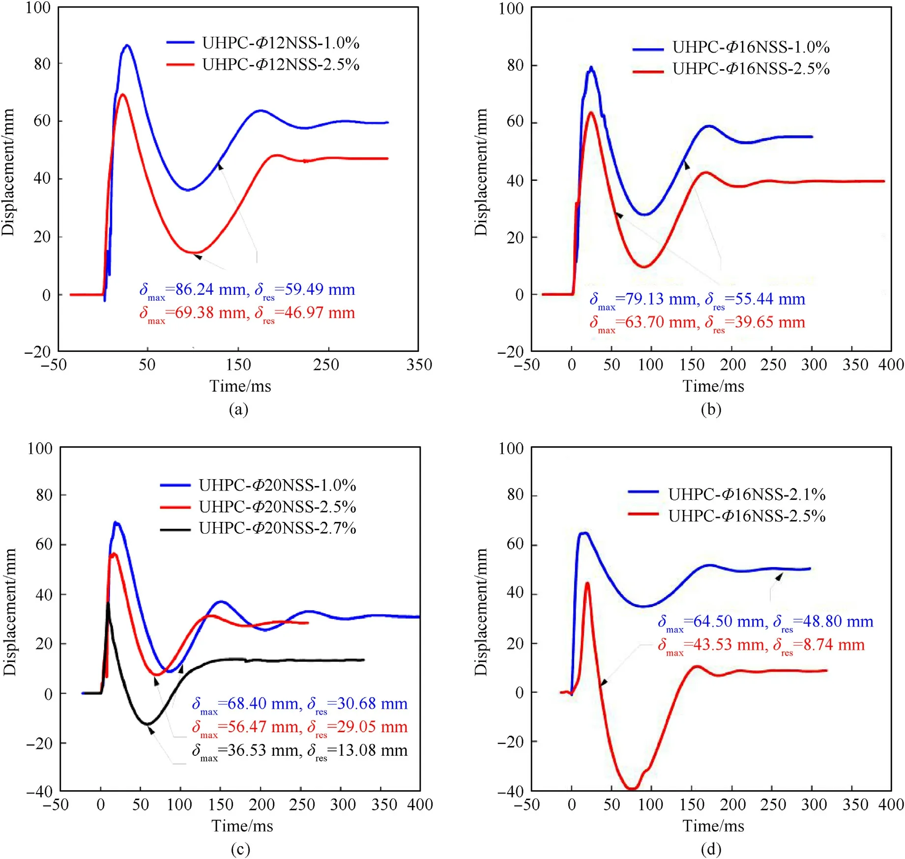
Fig.5.Assessment of beam deflections with various fiber contents: (a) UHPFRC-Φ12 NSS; (b) UHPFRC-Φ16 NSS; (c) UHPFRC-Φ20 NSS; (d) UHPFRC-Φ16 HSS.
3.2.Impact of high-strength longitudinal rebar on the UHPFRC blasting performance
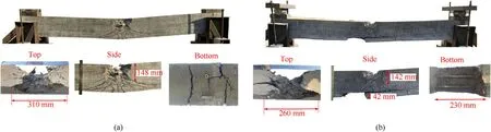
Fig.6.Damage modes of UHPFRC-Φ12 NSS beams with varying fiber contents: (a) UHPFRC-Φ12 NSS-1.0%; (b) UHPFRC-Φ12 NSS-2.5%.

Fig.7.Damage modes of UHPFRC-Φ16 NSS beams with varying fiber contents: (a) UHPFRC-Φ16 NSS-1.0%; (b) UHPFRC-Φ16 NSS-2.5%.
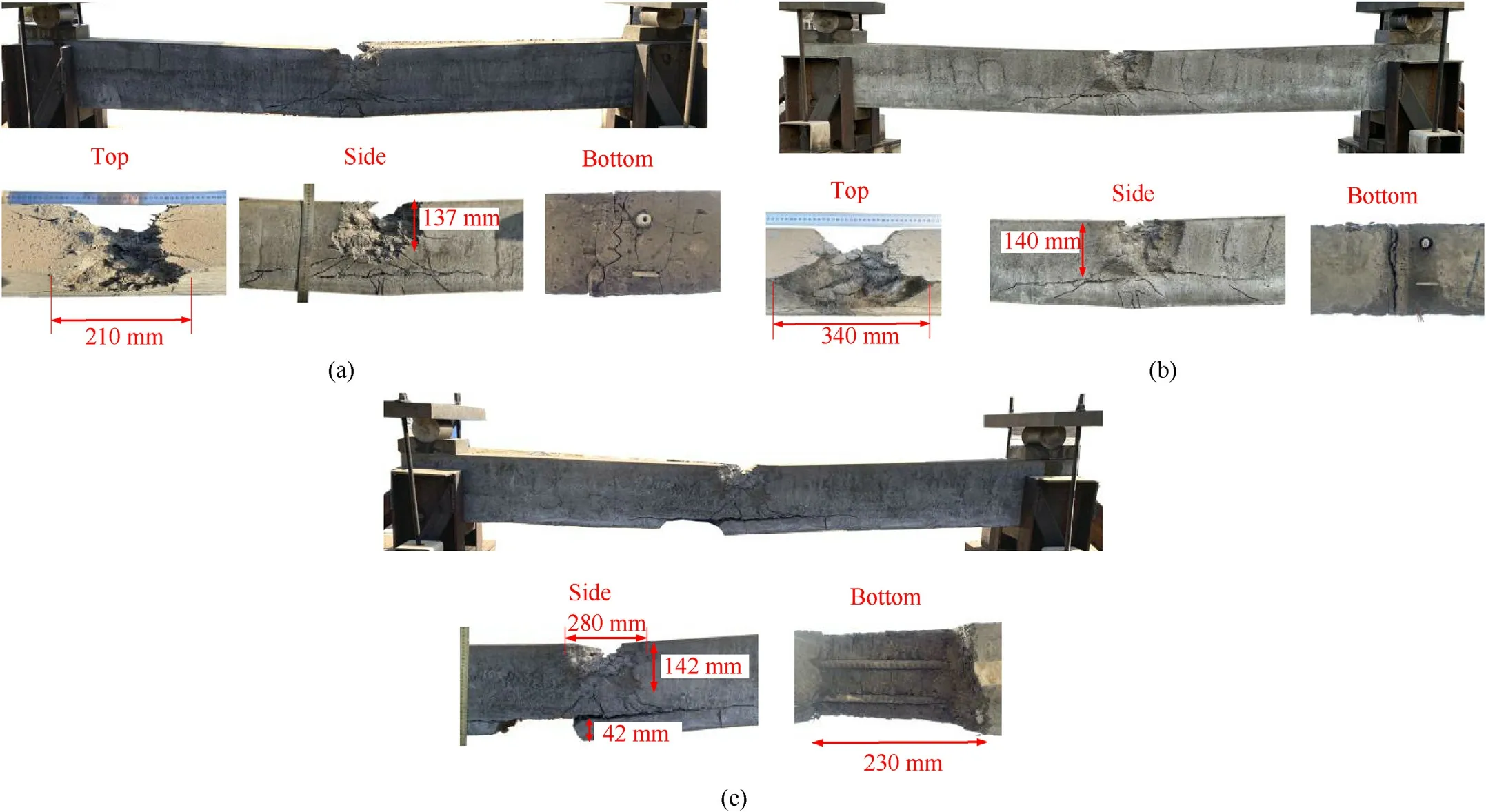
Fig.8.Damage modes of UHPFRC-Φ20 NSS beams with varying fiber contents: (a) UHPFRC-Φ20 NSS-1.0 %; (b) UHPFRC-Φ20 NSS-2.5 %; (c) UHPFRC-Φ20 NSS-2.7 %.
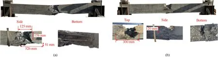
Fig.9.Damage modes of UHPFRC-Φ16 HSS beams reinforced with varying fiber contents: (a) UHPFRC-Φ16 HSS-2.1 %; (b) UHPFRC-Φ16 HSS-2.5 %.

Fig.10.Assessment of beam deflections with NSS and HSS.
The blasting behaviors of UHPFRC beams with NSS and HSS longitudinal reinforcements are explored by assessing the deformation responses(see Fig.10)and damage modes(see Fig.11).The results illustrate that HSS decreases the deformation of UHPFRC beams relative to NSS.From Fig.10, for Z=0.198 m/kg1/3, the explosion leads to maximum and residual displacements of δmax=63.70 mm and δres=39.65 mm for the UHPFRC-Φ16 NSS-2.5%beam.In contrast,the UHPFRC-Φ16 HSS-2.5%beam exhibits a drop of approximately 31.66% in maximum displacement(δmax=43.53 mm) and 77.96 % in residual displacement(δres= 8.74 mm).In addition, when subjected to larger blasting loads (Z=0.184 m/kg1/3), the UHPFRC-Φ16 HSS-1.0% beam experiences smaller maximum and residual displacements of δmax= 54.19 mm and δres= 1.90 mm, respectively, relative to the UHPFRC-Φ16 NSS-1.0 % beam.Reinforcement with HSS boosts the resistance levels of UHPFRC beams to flexural deformation relative to reinforcement with NSS.
Fig.11 shows a comparison of the damage modes of the UHPFRC beams reinforced with NSS and HSS.All three specimens show compressive side crushing and midspan fractures.WhenZ=0.198 m/kg1/3,the reinforcement type has little influence on the UHPFRC beam failure mode.The lengths of the crushing zone are 300 mm for the UHPFRC-Φ16 NSS-2.5%and UHPFRC-Φ16 HSS-2.5%beams.The UHPFRC-Φ16 NSS-2.5% beam experiences more cracks in the tensile zone than the UHPFRC-Φ16 HSS-2.5 % beam.
3.3.Impact of longitudinal RR
The blast performance characteristics of UHPFRC beams were evaluated using three different longitudinal RRs generated by altering the reinforcement diameters from 12 mm to 16 mm and 20 mm.The beam deflection comparisons for the studied cases are depicted in Fig.12.When Z=0.198 m/kg1/3, UHPFRC-Φ16 NSS-1.0%exhibits drops in the maximum displacements by 8.24% and residual displacements by 6.81% relative to UHPFRC-Φ12 NSS-1.0%.Changing from Φ16 to Φ20 bars decreases the maximum displacement by 15.69% under the same blast force.This result holds valid for both 1.0 vol% and 2.5 vol% steel fiber-reinforced UHPFRC beams.The findings indicate that elevating the longitudinal RR has a beneficial impact on the blasting characteristics of UHPFRC beams.
As shown in Figs.13 and 14, under the same close-in blasting load, increasing the longitudinal RR does not reveal a clear improvement in the ability of the UHPFRC beam to resist local damage, such as crushing, cracking, and spalling.For UHPFRC beams with 1.0 vol% of fiber (see Fig.13), all three UHPFRC beams with Φ12, Φ16 and Φ20 exhibit similar damage modes of concentrated crushing with multiple crack formations along the flexural area.The length of the crushing zone of an UHPFRC beam increases with an increase in the longitudinal reinforcement diameter.In addition, the UHPFRC-Φ12 NSS-2.5% beam experiences severe spalling of the rear surface concrete,whereas the remaining beams exhibit only damage in the form of cracks.
To conclude, these outcomes illustrate that increasing the fiber content, increasing the longitudinal RR, and using HSS instead of NSS have important benefits for boosting the resistance levels of UHPFRC beams to flexural deformation from blast loading.However, none of these parameters exhibit significant effects on damage modes, such as crushing, spalling and cracks, at the studied scaled distances.
4.Numerical analysis
4.1.Numerical model

Fig.11.Comparing the damage modes of the UHPFRC beam reinforced with NSS and HSS: (a) UHPFRC-Φ16 NSS-2.5%; (b) UHPFRC-Φ16 HSS-2.5% under a 2 kg TNT blast load; (c)UHPFRC-Φ16 HSS-2.5% under a 2.5 kg TNT blast load.

Fig.12.Assessment of beam deflections with different longitudinal RRs: (a) UHPFRC beam with 1.0% fiber by volume; (b) UHPFRC beam with 2.5% fiber by volume.
By applying finite element (FE) analysis with LS-DYNA, the failure modes and blasting behaviors of the beams were further examined.Fig.15 presents the 3D numerical model.To precisely evaluate the influences of fiber parameters, UHPFRC was analyzed using mesoscale simulations of a composite of two materials:mortar and steel fibers.Liang and Wu[46],Lee et al.[47]and Zhang et al.[48] demonstrated this mesoscale model for accurately simulating the UHPFRC dynamic response exposed to impacts and blast loads.Solid elements (mesh size of 5 mm × 5 mm × 5 mm)were used to model the mortar.Discretely dispersed fibers were achieved by utilizing a MATLAB script to embed 3-node beam components with equal and random distributions into the UHPFRC matrix.Volumetric ratios of 1.0%, 2.1%, 2.5%, and 2.7% were considered in accordance with the existing straight fiber shape.Each fiber was represented by a beam section with a 6.5-mm mesh size.Beam elements (mesh size of 5 mm) were used to model the bars.This mesh size was chosen to strike a balance between the accuracy of the numerical model predictions and the computational cost.A numerical converging analysis demonstrates that further reducing the element size does not affect the associated findings.Additionally,it was observed that adopting a smaller mesh may compromise computational efficiency.This mesh size also corresponds to Refs.[29,49].In addition, the solid element(*SECTION_SOLID) was employed to model the simply supported boundary conditions of the RC beam in the experiment.The modeling of the interface between the RC column and the rigid plate was carried out through the utilization of the "AUTOMATIC_SURFACE_TO_SURFACE" keyword.
To represent air, solid components with mesh sizes of 15 mm were employed.Refs.[50-52] adopted similar mesh sizes for air.*INITIAL_VOLUME_FRACTION_GEOMETRY keyword [53] was utilized for modeling cylindrically shaped explosives, which allows the determination of original volume fractions for multiple materials in multimaterial arbitrary Lagrange-Euler elements.All air domain surfaces were equipped with the*BOUNDARY_NON_REFLECTING keyword to avoid false reflections of the pressure waves.In this study,the ALE method[54]using the*CONSTRAINED_LAGRANGE_IN_SOLID keyword was chosen to couple the Eulerian parts (air and explosive) and Lagrangian parts(UHPFRC beam and support).

Fig.13.Damage mode of the UHPFRC beam with 1.0 vol% of fiber using different longitudinal RRs: (a) Φ12; (b) Φ16; (c) Φ20.

Fig.14.Damage mode of the UHPFRC beam with 2.5 vol% of fiber using different longitudinal RRs: (a) Φ12; (b) Φ16; (c) Φ20.
4.2.Material models
4.2.1.AirandTNT
Both materials were identified by*ALE MULTI MATERIAL GROUP[52] in the numerical model.The exploding detonation properties for TNT were controlled using the keyword *MAT_HIGH EXPLOSIVE_BURN.The Jones-Wilkins-Lee (JWL) equation establishes the pressure from the initial energy per initial volume(E)and the relative volume (V) in the EOS of TNT as follows:
Fig.15.FE model: (a) UHPFRC beam and support models; (b) UHPFRC model; (c) ALE model.

Table 5Air properties.

Table 6TNT properties(*MAT_HIGH_EXPLOSIVE_BURN).
whereA,B,R1andR2are explosive-related variables.The*MAT_NULL keyword represents air.The parameters utilized for air and TNT are detailed in Ref.[54].The parameters utilized for air and TNT are also given in Tables 5 and 6, respectively Refs.[54,55].
4.2.2.Mortar
The*MAT_WINFRITH_CONCRETE keyword[48]has been shown to properly replicate the dynamic behavior for UHPFRC mortar during blast loading [29,47].This concrete model is useful in circumstances with limited empirical data, and it is simple to input parameters, including tensile strength, compressive strength, and fracture energy.The values for the compressive strength, tensile strength,and fracture energy of the mortar,which are essential for constructing the mesoscale model, were obtained from Refs.[47,48].Furthermore, this model incorporates the consideration of the strain rate effect as per the guidelines outlined by the CEB[56].To determine the concrete strength,the initial value was multiplied by an enhancement factor that accounts for the influence of the strain rate.The following equations were employed for calculating the enhancement factors for tensile (ET) and compressive (EC) strength:
here,fcuis the concrete cube strength in MPa.
The Young's modulus rate enhancementEEis calculated as an average of tensile and compressive rate enhancements:
If any of the aforementioned rate enhancement factors are found to be less than one, they are adjusted to a value of one,indicating the absence of any rate enhancement.The material parameters of the mortar are summarized in Table 7.To prevent mesh misrepresentation and graphically represent the local damage of UHPFRC, an erosion algorithm (*MAT_ADD_EROSION) was incorporated into this model, permitting the erosion of concrete once a maximum principal strain of 0.04 is attained, as described in Ref.[48].
4.2.3.Rebarsandsteelfibers
By utilizing the *MAT_LINEAR_PIECEWISE_PLASTICITY(*MAT#24) keyword, the stress‒strain responses of the NSS and HSS are predicted.The stress‒strain relationships shown in Fig.2 are utilized to establish the model parameters, and the Malvar and Crawford[57]model is chosen to account for strain rate effects.Table 8 shows the reinforcement models used in the numerical study.Additionally, steel fibers are simulated with the*MAT_PLASTIC_KINEMATIC key card.The Poisson's ratio, Young's modulus, and failure strain are determined using the single fiber pull-out test referred to in Ref.[58] and given in Table 9.
4.3.Bond slip model
Lee et al.[47] and Fang and Zhang [59] applied the keyword*CONTACT_1D in LS-DYNA to model the bonding and slipping effects of fibers and the matrix of a UHPFRC beam subjected to blast and impact loading.Furthermore,the interaction between the steel longitudinal reinforcement and concrete is considered[60-62].For the keyword*CONTACT_1D in LS-DYNA,it is hypothesized that the bond is elastic‒plastic and that the maximum shear stress is τmax.The present model incorporates fictitious springs to enable the nodes within the rebar beam element to slide along the concrete solid element, as depicted in Fig.16.

Table 7Material properties of the UHPFRC mortar.

Table 8Characteristics of the rebar.

Table 9Material properties of the steel fibers.

Fig.16.Contact 1D model: (a) Illustration of the hypothetical spring connecting the master and slave nodes; (b) Illustration of a bond-slip interrelationship.

Table 10Contact parameters between the steel fibers and mortar.
In this contact type,the interface bond can be defined as follows, whereGsis the bond shear modulus (MPa),umaxis the maximum elastic slip (mm),hdmgis the damage curve exponent andDis the damage parameter.The properties of bond slip obtained from Refs.[29,47,63,64] were applied for steel fibers and longitudinal reinforcement, respectively, and these properties are presented in Table 10.Su et al.[63] investigated the impact of the one-dimensional bond-slip behavior of the fiber-mortar interface of UHPFRC through fiber pull-out tests.Furthermore, a numerical model incorporating a Contact-1D model was developed,and its accuracy was confirmed through results obtained from impact [63] and blast [47] experiments.Yoo [64] conducted empirical investigations of the bond behavior of steel reinforcement in UHPFRC, encompassing parameters such as slip capacity,bond strength,and failure mode.Based on extensive experimental data,an enhanced model for predicting the bond strength between steel reinforcement and ultrahigh-performance concrete was proposed, as outlined below:
here, τmaxrepresents the bond strength, whiledenotes the compressive strength of the samples [65].
4.4.Validation of the FE model
The homogenous UHPFRC is modeled using the*MAT_WINFRITH_CONCRETE material model (MAT#084) to compare the mesoscale and macroscale approaches.The material properties of the homogenous UHPFRC are referred to in Refs.[14,29].Fig.17 shows the typical posttest failure modes of the UHPFRC-Φ16 NSS-1.0%and UHPFRC-Φ16 HSS-2.5%beams from the experimental and numerical results.The explosion causes severe lateral bending and concrete crushing on the top face of each UHPFRC beam.The results demonstrate that a mesoscale numerical approach can better simulate this damage mode than a macroscale numerical approach.
Fig.18 illustrates the differences between typical numerical and experimental displacement‒time histories for the UHPFRC-Φ12 NSS-1.0% and UHPFRC-Φ16 NSS-2.5% beams.Overall, the results show that the mesoscale approach can better predict the deformation characteristics of UHPFRC beams subjected to close-in blast loading.The disparity in deflection values can potentially be attributed to the fact that the numerical model restricted the rotation of the top iron block of the support,as opposed to the field test depicted in Fig.3,where the top steel blocks were affixed to a base using a reinforcement that allowed for slight rotation, subsequently influencing the damage mode.Furthermore, in the experimental setup,the boundaries were bolted,leading to a preload that could impact the deflection of the beam.Therefore, it is recommended to incorporate a more accurate boundary condition in future research to attain enhanced precision.
Table 11 displays the overall comparison between the mesoscale numerical and experimental maximum displacements (δnumand δexp).The average inaccuracy for all beams and explosion scenarios is 6.22%.In general, the computational predictions for UHPFRC beams subjected to close-in explosions are consistent with the experimental findings.This correlation implies that the numerical method can accurately compute the maximum midspan deflections of UHPFRC beams under blast loading circumstances.
4.5.Parametric investigation
To further explore the effects of fiber reinforcements on the close-in explosion characteristics of UHPFRC beams, parametric assessments of the steel fiber content, steel fiber length and fiber material type were performed based on the above verified numerical approach.The dynamic responses of the UHPFRC beams were evaluated at a 0.25 m standoff distance,starting with 1 kg of equivalent TNT that is increased by an increment of 0.5 kg until beam failure.
4.6.Effect of steel fiber content
The blast performance levels of UHPFRC beams with five fiber contents (1.0 vol%, 2.0 vol%, 2.5 vol%, 3.0 vol% and 3.5 vol%) were further investigated.The findings of the analysis were described by contrasting maximum midspan deflections.The results of the midspan displacement ratio, which is the ratio of the largest midspan displacement to the midpoint of the beam length, were compared.Generally, the numerical results of the analysis are in agreement with the test results,as depicted in Fig.19.The increase in fiber content decreases the midspan displacement of the beam.For example,when the charge mass is 3 kg,the UHPFRC beam with 1.0% fiber content is totally fractured.The maximum midspan displacements for UHPFRC beams with 2.1 vol%,2.5 vol%,3.0 vol%and 3.5 vol% of fiber are 113.0 mm, 97.5 mm, 81.1 mm and 76.1 mm,respectively.In addition, as the fiber volume percentage increases from 1.0% to 2.1%-2.5%, the UHPFRC beam can resist a larger blast load.The largest blast loads that UHPFRC beams with 1 vol%,2.1 vol% and 2.5 vol% of steel fiber can resist are 2 kg, 3 kg, and 3.5 kg,respectively.However, further increases in the fiber volume percentage from 3.0% to 3.5% do not increase the failure blast load.Therefore, 3.0 vol% of fiber is sufficient to improve the blast resistance of the UHPFRC beam.

Fig.17.Comparison of failure modes: (a) UHPFRC-Φ16 NSS-1.0% at a 0.20-m/kg1/3 scaled distance; (b) UHPFRC-Φ16 HSS-2.5% at a 0.18-m/kg1/3 scaled distance.
Fig.20 shows further comparisons of the damage modes of UHPFRC beams at 60 ms with 1.0, 2.5, and 3.5 vol% of steel fibers subjected to a 3-kg TNT explosion.Clearly, increasing the fiber content can reduce local beam damage.The 3-kg TNT explosion causes bending and localized crushing damage to the UHPFRC beams with 3.5 vol% steel fibers.As the fiber volume percentage decreases to 2.5%and 1.0%,the damage area increases.In addition,the beam with 1.0 vol% steel fiber exhibits shear damage at the support.Therefore,increasing the volume percentage of steel fibers enhances the local damage control of the investigated UHPFRC beam.This improvement is attributed to the corresponding advancements in compressive strength and tensile strength with the augmentation of fiber content, as substantiated by Refs.[42,66],respectively.
4.7.Effect of steel fiber length
Wu et al.[17],Huang et al.[16]and Abbas et al.[67]investigated the impacts of steel fiber length on the mechanical characteristics of ultrahigh-performance concrete.These studies examine fiber length differences spanning from 6 to 16 mm.The results show that the steel fiber size significantly affects the dynamic compressive[17] and flexural [67] properties.However, limited studies have focused on the effects of fiber length on the blast performance levels of UHPFRC beams.To examine the impacts of the steel fiber length on the dynamic behaviors of UHPFRC beams, four fiber lengths of 6 mm [17], 8 mm [67], 13 mm and 16 mm [67] were considered.In the parameter analysis, the fiber diameter was maintained at 0.2 mm,and the fiber volume fraction was 2.5%for all beams.
Fig.18.Sample comparison results of the mesoscale and macroscale approaches: (a) UHPFRC-Φ12 NSS-1.0 %; (b) UHPFRC-Φ16 NSS-2.5 %.

Table 11Comparison of maximum numerical and experimental maximum midspan displacements.
Fig.19.Influences of the fiber content on the deformation characteristics of the UHPFRC beams: (a) Displacement-charge mass relationship; (b) Displacement ratio-scaled distance history.
The maximum midspan displacement and midspan displacement ratio values of the UHPFRC beams with different steel fiber lengths at various scaled distances are shown in Fig.21.In general,UHPFRC beams with 6-mm-long fibers exhibit the smallest deformation relative to beams with longer fibers.For instance, under a 3-kg blast load,the midspan displacement decreases from 97.5 mm to 85.6 mm, 83.6 mm, and 80.4 mm when the steel fiber length changes from 13 mm to 8 mm,16 mm,and 6 mm,respectively.This decrease in midspan displacement because of varying fiber length holds true for all scaled distances.In addition, the UHPFRC beams with fiber lengths of 6 mm and 8 mm can withstand a maximum blast load of 4 kg,whereas steel fiber lengths of 13 mm and 16 mm decrease the blast load to failure.As explained in Ref.[17], the relatively short fibers,i.e.,6 mm and 8 mm,inhibit the initiation of microcracks.The 16-mm-long fibers can sustain the load of larger cracks.Therefore, the relatively short (6 mm and 8 mm) and long(16 mm) fiber lengths enhance the anti-blast performance of the UHPFRC beam over that with 13-mm-long fibers.
Fig.20.Influences of steel fiber content on the damage modes of UHPFRC beams under a 3-kg TNT blast load: (a) 1.0 vol% at 60 ms; (b) 2.5 vol% at 60 ms; (c) 3.5 vol% at 60 ms.

Fig.21.Influence of the steel fiber length on the deformation characteristics of the UHPFRC beams: (a) Displacement-charge mass relationship; (b) Displacement ratio-scaled distance history.
Fig.22 depicts a comparison of the typical damage patterns of UHPFRC beams with various fiber lengths.The results indicate that beams with shorter fibers sustain less localized damage.The crushing lengths for the beams with relatively long fiber lengths of 13 mm and 16 mm are 327 mm and 289 mm, respectively.The crushing lengths decrease to 278 mm and 251 mm when the fiber length decreases to 6 mm and 8 mm,respectively.Fig.23 shows the energy absorption characteristics of the UHPFRC beams.Fig.23(a)shows that most of the explosion energy is absorbed by the motor and fibers.Under a 2-kg blast load, the energies absorbed by the mortar, fiber and reinforcement account for 83.98%, 12.04% and 0.04% of the total energy, respectively.As shown in Fig.23(b), the 13-mm and 16-mm fibers absorb more energy than the 6-mm and 8-mm fibers,and the corresponding damage is greater.Therefore,a beam with shorter fibers has superior anti-explosion performance and requires more explosion energy for destruction.In summary,the results illustrate that 6-mm steel fiber has important benefits for improving the blast resistance levels of UHPFRC beams.
4.8.Hybrid effects of steel fiber and various types of microfiber

Fig.22.Influence of steel fiber length on the damage modes of UHPFRC beams under a 2-kg TNT blast load:(a)6-mm fiber length;(b)8-mm fiber length;(c)12-mm fiber length;(d) 16-mm fiber length.
In addition to steel fiber,other types of fibers,such as glass fiber(GF), basalt fiber (BF) and polypropylene fiber (PPF), are widely used in UHPFRC.The effect of the fiber type has been demonstrated to affect the ductility enhancement in UHPFRC [20].Kang [19]experimentally found that including BFs can decrease the compressive strength and tensile strain capacity and improve the cracking strength and ultimate tensile strength.In addition, the UHPFRC with a combination of steel and polyethylene fibers shows a relatively high cracking strength, ultimate tensile strength, and tensile strain capacity.However, studies on the effects of the fiber type on the blast performance characteristics of UHPFRC beams are limited.Henceforth, a comprehensive analysis was conducted on four distinct categories of fibers,namely,steel fiber,BF,PPF,and GF.These fibers were modeled by the *MAT_PLASTIC_KINEMATIC keyword.The material properties were based on Ref.[20]and given in Table 12.
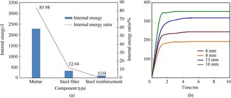
Fig.23.Energy absorption characteristics of the UHPFRC beams under a 2 kg TNT blast load:(a)Energy absorption characteristics of different components of a UHPFRC beam with 13-mm-long fibers; (b) Comparison of the internal energies of beams with different fiber lengths.

Table 12Material properties of the different fibers [20].
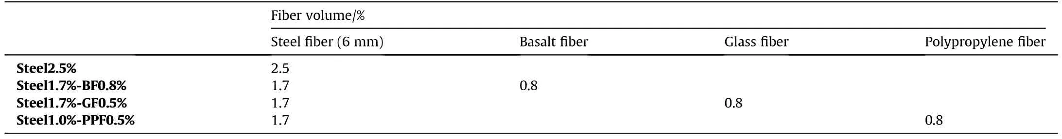
Table 13Hybrid fiber contents.
The contents of the fibers utilized to examine the effect of a hybrid combination of steel fiber and various types of microfiber on the blast performance characteristics of UHPFRC beams are presented in Table 13.In all four mixtures,the amount of fiber remains constant,at 2.5%by volume.The steel 2.5% beam(2.5 vol% of steel fiber) is a control mixture, in which steel fiber with a length of 6 mm is added to the UHPFRC mortar.Steel1.7%-BF0.8%,Steel1.7%-GF0.8 %, and Steel1.7%-PPF0.8 % beams are hybrid fiber UHPFRC beams with BF, PPF, and GF at 32% volume replacements,respectively.
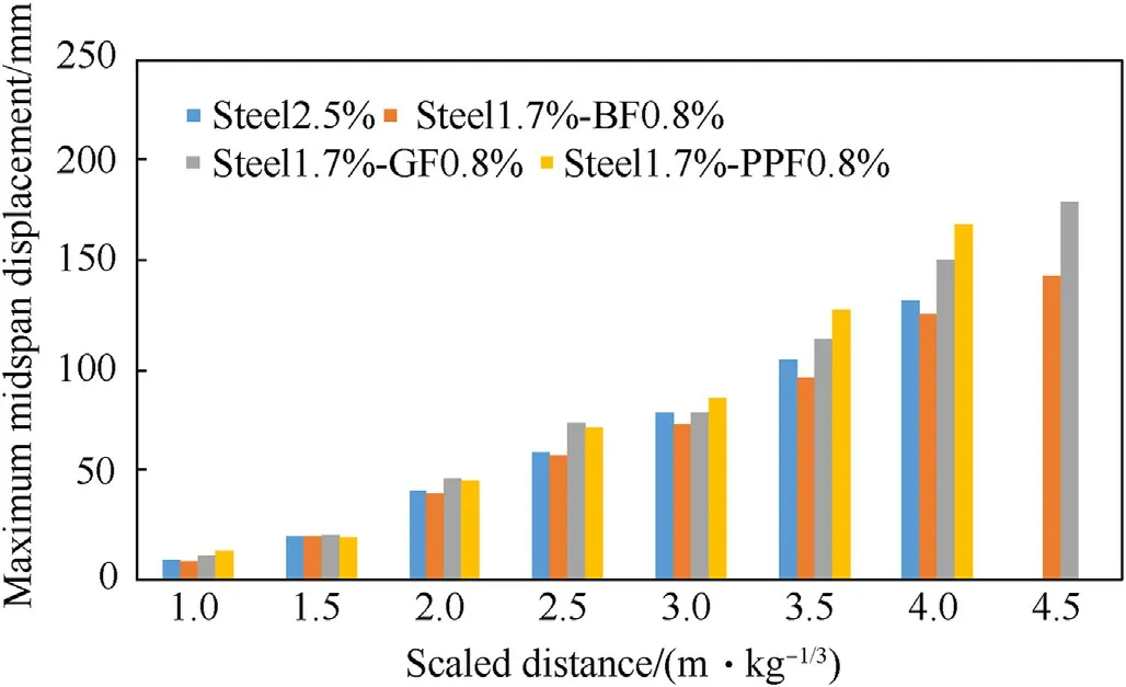
Fig.24.Influences of fiber type on the deformation characteristics of UHPFRC beams.
A comparison of the deformation aspects is shown in Fig.24.In general, the beam with 1.7 vol% of steel fiber and 0.8 vol% of BF undergoes the smallest midspan displacement.For example, the addition of BF results in a minimum midspan displacement of 128 mm when exposed to a 4-kg TNT explosion.Fig.25 shows a comparison of the energy dissipation characteristics of UHPFRC beams with different types of fibers subjected to a 4-kg TNT explosion.The beam containing a combination of steel fiber and BF absorbs the least amount of energy and requires more blast energy to destroy.Moreover, the UHPFRC beam strengthened with steel fiber combined with BF and GF can withstand the largest blast load of 4.5 kg TNT.The addition of microfibers delays crack formation.Important studies [19, 68, 69] reveal that a combination of macrofibers with diameters greater than 0.5 mm and microfibers with diameters smaller than 0.022 mm can prevent fracture formation at various phases of the failure process, hence enhancing the mechanical behavior of the concrete.In summary, the hybrid fiber system combining steel fiber and BF is effective for improving the blast resistance levels of UHPFRC beams.
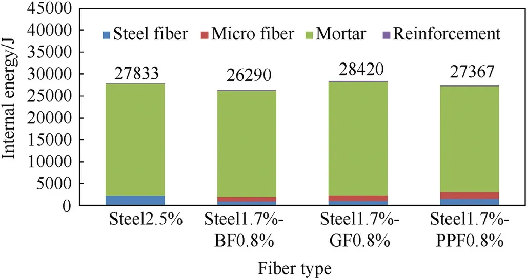
Fig.25.Energy dissipation characteristics of UHPFRC beams with different fiber types under a 4 kg TNT blast load.
5.Conclusions
As described in this paper,numerous field tests were conducted to explore the dynamic responses of UHPFRC beams under close-in explosions.Throughout the experiment, the influences of fiber content on UHPFRC beams were investigated.This research also included an examination of the longitudinal RR and the type of longitudinal reinforcement used.A comprehensive mesoscale numerical model comprising UHPFRC mortar,steel fibers,longitudinal reinforcement, explosions and air was established to simulate the blast characteristics of test beams.This approach offers the distinct advantage of scrutinizing the impact of fiber properties on the behavior of UHPFRC beams.By utilizing the verified numerical method,parametric studies were performed to further examine the impacts of steel fiber content and size and the hybrid effects of steel fibers, as well as microfibers.The subsequent conclusions were reached.
(1) Increasing the fiber content greatly improves the UHPFRC beam bending resistance, reducing the midspan displacement and increasing the beam capability to tolerate relatively high explosive loadings prior to failure.The experimental results indicate that under a 2-kg blast load,increasing the fiber content within 1.0 vol% and 2.5 vol%leads to greater spalling damage because of the uneven fiber distribution and agglomeration of steel fibers caused by the high fiber content.However, when evenly distributed steel fibers were considered, the numerical results demonstrate that increasing the steel fiber content leads to improved control of the local damage modes of the UHPFRC beams,including less crushing and shear damage.
(2) The length of the fibers has a significant effect on the explosion behavior of the UHPFRC beam.In comparison to beams employing 13-mm- and 16-mm-long fibers, the UHPFRC beams using 6-mm- and 8-mm-long fibers demonstrate greater blasting resistance, covering smaller lateral displacements and local crushing damage because microcrack initiation is more effectively inhibited.In addition, the UHPFRC beam using 16-mm-long fibers exhibits higher blast resistance than that using 13-mm-long fibers.Larger cracks can be prevented more effectively by the 16-mm fibers than by the 13-mm fibers.
(3) Adding BF and steel fiber while maintaining the total volume fraction can boost the blasting resistance of a UHPFRC beam,reduce the midspan displacement and increase the blast load and energy required to reach failure.This phenomenon occurs because the inclusion of microfibers with high strengths prevents the creation of cracks.However, using PPF or GF instead of BF increases the deformation of the UHPFRC beams because of their reduced yield strength and failure strain properties.
(4) Increasing the longitudinal RR and employing high-strength longitudinal reinforcement greatly boosts the bending resistance levels of UHPFRC beams, thus decreasing the maximum displacement.However, increasing the longitudinal RR and utilizing high-strength reinforcement do not discernibly affect the resistance of a UHPFRC beam to local damage modes, such as crushing and spalling.
Declaration of competing interest
The authors declare that they have no known competing financial interests or personal relationships that could have appeared to influence the work reported in this paper.
Acknowledgments
This work was supported by the National Natural Science Foundation of China (Grant No.12102050) and the Open Fund of State Key Laboratory of Explosion Science and Technology (Grant No.SKLEST-ZZ-21-18).

- Defence Technology的其它文章
- The interaction between a shaped charge jet and a single moving plate
- Machine learning for predicting the outcome of terminal ballistics events
- Fabrication and characterization of multi-scale coated boron powders with improved combustion performance: A brief review
- Experimental research on the launching system of auxiliary charge with filter cartridge structure
- Dependence of impact regime boundaries on the initial temperatures of projectiles and targets
- Experimental and numerical study of hypervelocity impact damage on composite overwrapped pressure vessels