
Adaptive Robust Servo Control for Vertical Electric Stabilization System of Tank and Experimental Validation
2024-02-29 08:23DruiLinXiuyeWngYiminWngGuoliYng
Defence Technology 2024年1期
Drui Lin , Xiuye Wng ,*, Yimin Wng , Guoli Yng
a School of Mechanical Engineering, Nanjing University of Science and Technology, Nanjing, 210094, China
Keywords: Adaptive robust servo control Experimental validation Nonlinearity compensation System uncertainty Vertical electric stabilization system
ABSTRACT A tracking stability control problem for the vertical electric stabilization system of moving tank based on adaptive robust servo control is addressed.This paper mainly focuses on two types of possibly fast timevarying but bounded uncertainty within the vertical electric stabilization system: model parameter uncertainty and uncertain nonlinearity.First,the vertical electric stabilization system is constructed as an uncertain nonlinear dynamic system that can reflect the practical mechanics transfer process of the system.Second,the dynamical equation in the form of state space is established by designing the angular tracking error.Third, the comprehensive parameter of system uncertainty is designed to estimate the most conservative effects of uncertainty.Finally, an adaptive robust servo control which can effectively handle the combined effects of complex nonlinearity and uncertainty is proposed.The feasibility of the proposed control strategy under the practical physical condition is validated through the tests on the experimental platform.This paper pioneers the introduction of the internal nonlinearity and uncertainty of the vertical electric stabilization system into the settlement of the tracking stability control problem,and validates the advanced servo control strategy through experiment for the first time.
1.Introduction
The vertical stabilization system is a vital component of the bidirectional stabilization system of the tank, which has a significant impact on the stable accuracy of tank gun[1,2].The traditional vertical stabilization system mainly adopts electro-hydraulic drive[3,4], which has the defects of low transmission efficiency, large space occupation and poor control accuracy.The vertical electric stabilization system not only overcomes the above-mentioned defects, but also fundamentally solves the problem of “running gas,bubbling water,dripping liquid,leaking liquid”of the hydraulic system.Besides, the overall control performance of system is improved.However,the nonlinear mechanisms,electromechanical coupling effects, and system uncertainties of the vertical electric stabilization system are relatively more complicated.Therefore,an in-depth analysis of the complex nonlinearity and uncertainty within the vertical electric stabilization system is required.
The main function of the tank vertical stabilization system is to control the pitching motion of the barrel to meet the input command requirements of fire control system [5].Considering the complex combat environment of modern warfare, the vertical stabilization system must accurately,efficiently and stably adapt to the changing pattern of the input command.The current control strategies applied to tank vertical stabilization system are mainly designed based on linear control theory [6,7] (e.g., classical threeloop control), which cannot effectively solve the time-varying nonlinearity, parameter uncertainty, and nonlinear coupling problems of the vertical electric stabilization system.To achieve the characteristics of fast response,high stabilization accuracy,and low disturbance fluctuation of the vertical electric stabilization system,it is imperative to explore an advanced servo control method for complex nonlinearity and uncertainty.
With the rapid development of modern control theory, many advanced control methods have been applied to the tank vertical stabilization system, such as sliding mode control [8,9], adaptive robust control [10-15], active disturbance rejection control[16-18], intelligent control [19-22], etc.Although these control methods have some outstanding advantages over the traditional control methods for handling nonlinearity and uncertainty of system, those advantages are limited to handle the simple timeinvariant nonlinearity and constant uncertainty.Furthermore, in most researches, the analytical model of vertical electric stabilization system is usually simplified to be approximately linear,so it is almost impossible to meet the increasing requirements of the control accuracy.In this paper,an analytical dynamics model for the vertical electric stabilization system with internal nonlinearity and uncertainty is established, which reflects the practical mechanics transfer process of the system.This is the first pioneering work in this paper.
In recent years, many scholars have proposed various control methods for complex uncertain mechanical systems[23-31].Chen,as an outstanding contributor to the development of uncertain mechanical systems, has recently done innovative work on constraint-following control of mechanical systems and uncertainty control with unknown bounds [32-36].Meanwhile, some scholars have also introduced the control methods of the uncertain mechanical systems into the field of tank stabilization system.Sun[37,38] solved the pointing tracking problem of marching turretbarrel systems by using the uncertain mechanical system control method.Ma[39] applied the uncertain mechanical system control method to a moving target tracking control problem for marching tank, and verified the tracking performance and stability of the control method through co-simulation.However, Sun and Ma's work mainly focused on the whole-vehicle nonlinearity and uncertainty of the tank.The internal nonlinearity and uncertainty of the vertical electric stabilization system is ignored and the control method has not been validated under the practical physical condition.In responds to the above deficiencies, in this paper, the complex nonlinearity and uncertainty within the vertical electric stabilization system is analyzed and the nonlinear mechanism functions and the comprehensive parameter of system uncertainty are introduced.On this basis, an adaptive robust servo control strategy is proposed to ensure the system tracking performance and stability.The feasibility of the proposed control method under the practical physical condition are verified through the tests of the experimental platform.This is the second pioneering work in this paper.
There are three major contributions in this paper.First,based on the in-depth analysis of the complex nonlinearity and uncertainty within the vertical electric stabilization system, a nonlinear analytical dynamics model of system is established.Second, the nonlinear mechanism functions and the comprehensive parameter of system uncertainty are designed to evaluate the combined effects of system parameter uncertainty and uncertain nonlinearity.Afterwards, the boundary of comprehensive uncertainty is estimated through an adaptive law to overcome the most conservative effects of uncertainty.Third, an adaptive robust servo control is proposed to ensure the system tracking performance and stability.The control performance is validated through simulation and the feasibility of proposed control method under the practical physical condition is further validated through the tests of the experimental platform.
In the meantime,there are three main novelties of the proposed method compared to the existing methods.First,the effects of the internal nonlinearity and uncertainty of the vertical electric stabilization system is introduced into the settlement of the tracking stability control problem.Second, the proposed method can effectively handle the combined effects of complex nonlinearity and uncertainty in the tracking stability control.Third, the proposed method is successfully implemented to the experimental platform of the vertical electric stabilization system,which validate the feasibility of the advanced servo control method under the practical physical condition.
2.Dynamic model of the vertical electric stabilization system
The configuration of the vertical electric stabilization system of tank is shown in Fig.1, which is mainly composed by three parts:power unit(DC motor),transmission unit(Gearbox-Ball screw-Pushrod) and load unit (Barrel, Cradle and Gun breech).The DC motor accepts the control signal and outputs the driving torque,then the driving torque is amplified by the gearbox and transformed by the ball screw into axial repetitive force of pushrod to drive the load unit in the vertical movement.

Fig.1.Structure sketch of the vertical electric stabilization system.
For introducing the three important units of the vertical electric stabilization system with complex uncertainty and nonlinearity more clearly,the system schematic is shown in Fig.2,where θmand φ are the angular displacement of load unit and the initial angle of transmission unit, respectively,l0is the initial length of transmission unit,O,O1,O2are respectively the trunnion center point,the lower hinge point of transmission unit and the centroid of load unit,lptis the distance from upper hinge point of transmission unit and trunnion center point.
2.1.The power unit: DC motor
The basic operating principle of DC motor is to convert the control input voltage into electromagnetic torque through the excitation flux interaction to drive the gearbox to move.Since the small value of armature inductance,the effect of armature current dynamics can be neglected, so the dynamic model of the power unit can be expressed as Ref.[40].
whereu(t) is the control input voltage,JpandBprespectively represent the moments of inertia and viscous damping coefficients of the motor,Tp(t)andTpt(t)are the motor torque and the gearbox input torque, respectively, θp(t) is the angular displacement of motor,ke,Randktrespectively represent the electromotive force constant,the total resistance of the armature circuit and the motor torque constant.
2.2.The transmission unit: gearbox - ball screw - pushrod
Considering that the process of amplifying torque in the gearbox is affected by gear backlash,the gear transmission process involving gear backlash nonlinearity is described as
whereIis the gear ratio,Tt(t) is the gearbox output torque,Tt(t-)denotes the value ofTt(t)at the previous moment,bis the backlash distance.At the process of controller design,Eq.(3)can be further expressed as
whered1(t)∈R is the transmission error, which is a bounded nonlinear function associated withTpt(t) and ˙Tpt(t).
Then, the gearbox output torque will be converted into axial repetitive force of the pushrod by the ball screw.According to the principle of action of ball screw, its dynamical model can be expressed as

Fig.2.Schematic of the vertical electric stabilization system: (a) Mechanical transfer process; (b) Geometric relationship.
where θt(t) is the angular displacement of screw,Jt,PhandBtrespectively represent the moments of inertia, the lead and the viscous damping coefficients of screw.s(t) is the displacement of pushrod,FL(t) is the load force on the pushrod,d2(t)∈R is the flexible deformation error, which is a second order differentiable bounded nonlinear function.It is worth noting that θp(t)=Iθt(t)by the principle of gearbox.
2.3.The load unit: barrel, cradle and gun breech
Barrel,cradle and gun breech are fixed together to form the load unit,and the main function of the tank vertical stabilization system is to control the pitching motion of the barrel (i.e., the load unit).Since the load unit has to maintain low-speed movement to overcome the effect of road fluctuations and other disturbances after moving to the firing angle, and the friction effect of the system is more significant at low speeds, it is necessary to introduce a dynamic friction model.While,for eliminating the non-differentiable term of the LuGre model and describing the real friction behavior more accurately, the following modified LuGre friction model is proposed[41]:
wheremi(i=1,2,3) are the magnitude level of different friction characteristics,ni(i=1,2,3) are the shape coefficients of different friction characteristics,denotes the Stribeck effect,denotes the coulomb friction torque,denotes the viscous friction torque.
As shown in Fig.2, the load unit rotates around the trunnion center point drove by the load force,so the dynamical model of the load unit can be expressed as
wheregis the constant of gravitation,Jmandmrespectively represent the moments of inertia and mass of the load unit,d3(t)∈R is external disturbance.
According to the geometric relationship in Fig.2, the pushrod displacement can be expressed as
Substitute it into Eq.(6)
By differentiation
and
With Eqs.(1)-(8)
Taking Eqs.(11) and (12) into Eq.(13),
3.Problem statement: angular tracking of the load unit
The pitching motion of the load unit controlled by fire control system can be regarded as an angular tracking problem, which means the angular position of the load unit θmneed to track a desired reference command signalfrom the fire control system with a satisfactory performance while regardless of the uncertainty and nonlinearity.Assume that:[t0,∞]→R is of class C2,andare uniformly bounded.Let
then
then substitute it into Eq.(14).
where
For the vertical electric stabilization system described in Eq.(18), the moment of inertia of load unitJm, the transmission errord1, the flexible deformation errord2, the external disturbanced3and the equivalent viscous damping coefficient of the power unit and transmission unitBeqare considered as the uncertainty,which can be decomposed into nominal and uncertain portions:
where the uncertain portions ΔJm,ΔBeq,Δd1,Δd2,Δd3are bounded,so
Remark 1.The flexible deformation errord2is associated with the load forceFL.Considering that the output signal of the actuator is bounded, there is an upper output limit for the load torqueFL.So the first order derivativeand the second order derivativeshould be bounded, which can be decomposed into nominal and uncertain portions.
LetM:= (K1+Jm)-1, with the decomposition ofJm
where
As a result, the state-space model of the vertical electric stabilization system can be described as
wheret∈R is the time,x(t)∈R2is the state variable,u(t)∈R is the control input, δ(t)∈℘is the uncertain parameter, ℘⊂R6is unknown and compact, which stands for the boundary of δ.In addition, g(x(t),t), Δg(x(t),δ(t),t), G(x(t)), ΔG(x(t),δ(t)) and ω(x(t),t)are matrices of appropriate dimensions, g(·), Δg(·), G(·), ΔG(·)and ω(·)are continuous functions which can be generalized to be Lebesgue measureable int.
Remark 2.As shown in Fig.3, an appropriate control inputushould be designed for the settlement of the angular tracking problem of load unit,which means the vertical electric stabilization system are driven to realize the approximation tracking and stabilization of pitch angle.On the other hand, the system can also render the uniform boundedness and uniform ultimate boundedness under complex time-varying uncertainty and uncertain nonlinearity disturbances.
4.Adaptive robust control servo strategy
4.1.Parameter for comprehensive representation of system uncertainty ε

Fig.3.Block diagram of the controller design idea.
This section analyzes the uncertainty boundary situation of the controlled system described by Eq.(29), and from this the representation parameter ε that can reflect the combined influence of the system uncertainty is constructed.At first, choose an appropriate functionto make the uncontrolled nominal system=g(x(t),t) to be uniformly asymptotically stable at the originx= 0, then, a first-order differential functionV1(x):R2×R→R+and continuous, strictly increasing function λi(·):R+→R+,i=1,2,3 are constructed to satisfy
which means that for the uncontrolled nominal system=g(x(t),t) there exists a legal Lyapunov functionV1(x).
Then, the bounding condition of the uncertain portions Δg and ΔG can be decomposed as
where G(x) is the determined matrix function, P(x,δ,t) and L(x,δ)are the uncertain matrix function.Besides
According to Eq.(19), the boundary ofK1can be described as
where
Define a function
then
sof(·) is strictly decreasing in ΔJmand, then there are
henceL>- 1, which means there exists a constant ζL>-1 such that
where κminrepresent the minimum eigenvalue.
The second thing, focus on the boundary condition of P for subsequent controller design
to obtain ‖P‖, the following extrapolation is made
Let
then Eq.(46) can be rewritten as
where
Remark 3.ε∈R+is the parameter for comprehensive representation of system uncertainty, which reflects the most conservative combined influence of all uncertainties of the system on dynamic characteristics.In addition,this paper addresses a complex class of nonlinear time-varying uncertainty control problems, where the time-varying uncertainty is bounded but the boundary of it is unknown, i.e., ε is unknown.For this purpose, an adaptive law ˙^ε is designed to estimate ε online, after that an adaptive robust controller is designed to suppress the uncertainty.
4.1.Adaptive robust controller design
where α1,2>0 are scalar constants that represent the design parameters of adaptive law.
Remark 4.This adaptive law is leaky,whereis the leakage type.is always non-negative to compensate for system uncertainty,andmakes the solution of the dynamic Eq.(51) in an exponentially decaying state until it goes to zero.As the system gradually reaches a steady state, the leaky adaptive law ensures that the estimated uncertainty bound is not too large, which can keep the control magnitude within acceptable limits and prevent excessive control costs.Based on this adaptive law, the adaptive robust control is proposed for the complex system Eq.(29).
where γ >0 is the design parameter.
Proof 1.With consideration of the controlled system, choose a legitimate Lyapunov function
The Lyapunov derivative is given by
Causing Δg=GP and ΔG=GL are known, according to Eq.(33),there is
Substitute Eqs.(51) and (52) into it, then
according to Eq.(44) and the Rayleigh principle, there is
Eq.(58) can be rewritten as
Substitute it into Eq.(61), there is
Based on the above analysis, the system practical stability described by Theorem 1 holds according to the reference.
(I)Uniform boundedness:For any ρ >0,if‖x(t0)‖<ρ there exists
(II) Uniform ultimate boundedness: For anythat satisfies
(III) Uniform stability: The controlled system shows uniform stability when chooses=ρ*
5.Simulation analysis
5.1.Parameter selections
In this section, the tracking performance and stability of designed controller will be tested through the simulation.Since,in practice, the desired reference command signal from the fire control system may be fixed or variable, two different operating conditions are considered in the simulation.In Case 1,the steady-state tracking performance of controller will be validated, the angular position of load unit of the vertical electric stabilization system is set to adjust from θm(0)=0 rad to θm(t) = 0.1× (1 -)rad,so the desired signals is set as= 0.1× (1 -)rad, the initial tracking errorse(0)=0 rad(i.e.,x1(0) =0),the other initial statex2(0)=0 and the initial value of adaptive law^ε(0) =0.In Case 2,the dynamic tracking performance of controller will be validated,the angular position of load unit of the vertical electric stabilization system is set to adjust from θm(0)=0 rad to θm(t) = 0.1×sin(0.2πt)rad, so the desired signals is set as= 0.1×sin(0.2πt)rad, the initial tracking errorse(0)=0 rad (i.e.,x1(0) =0),the other initial statex2(0)=0 and the initial value of adaptive law= 0.
For fully validating the suppression effect of the proposed control method on complex time-varying uncertainties, two types of system uncertainties, parameter uncertainty and uncertain nonlinearity, are considered in the simulation.For uncertain nonlinearity, choosed1(t) = 10 sint,d2(t) = 10 sint,d3(t) =10 sint.For parameter uncertainty, chooseJm= 3000+3000 sintkg·m2,Beq= 0.0675+ 0.0675 sintN·m·s/rad.
Through the analysis of Section 4, choose the functions,
So the uncontrolled nominal system can be described as
Converting it to matrix form
According to Eqs.(30)-(33), choose the lyapunov function,
where the matrix P can be determined with the lyapunov equation,
By choosinga1= 1,a2=2 and Q = [2 0;0 2], so P = [3 1;1 1].
In this paper, the PID control is introduced as the comparison method to validate the tracking performance and stability of the proposed control.The nominal system physical parameters chosen are listed in Table 1,the control parameters are given in Tables 2 and 3.
5.2.Simulation results
The simulation results are shown in Figs.4-12.Among them,the dynamic comparison results of tracking error in Case 1 and Case 2 are shown in Figs.4 and 8, respectively.From the simulation results,with the proposed control,the control response of the system is faster,besides,both tracking error in Cases 1 and 2 can converge and stabilize near zero after 4.5 s.However, with the PID control,the control response is slower which leads to a big abrupt change of the tracking error,besides,it takes longer time for tracking error to reach the steady state, and the tracking error in the steady state fluctuates more.
Table 1Nominal system physical parameters.

Table 2Control parameters of Case 1.
Table 3Control parameters of Case 2.

Fig.4.Comparative tracking error e in Case 1.
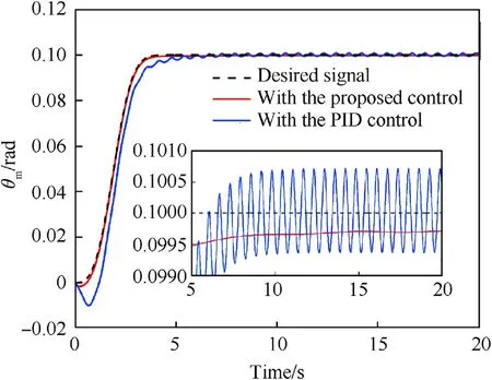
Fig.5.Comparative angular position θm in Case 1.
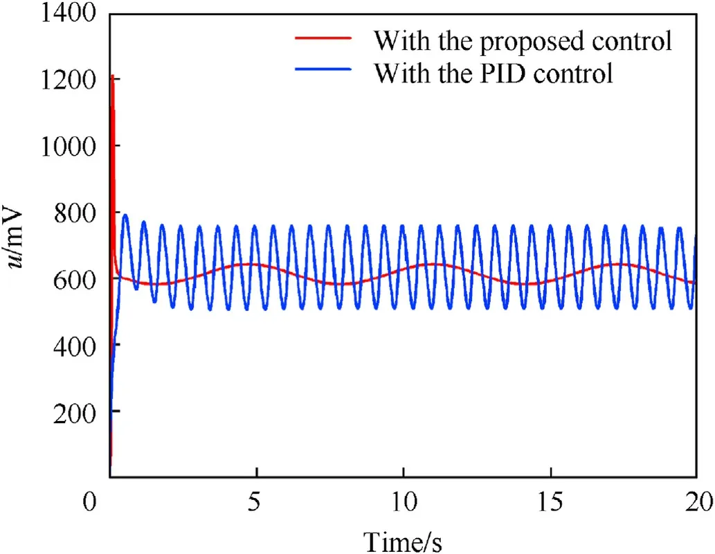
Fig.6.Comparative control input u in Case 1.
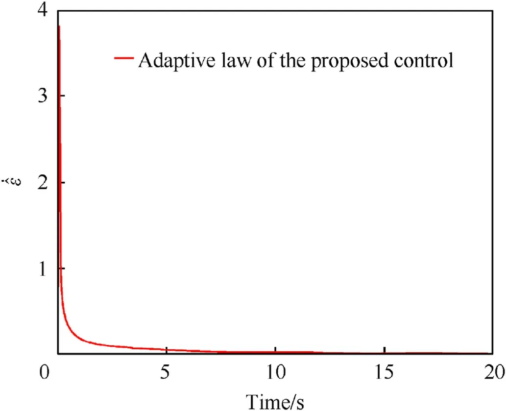
Fig.7.History of the adaptive law ˙^ε in Case 1.
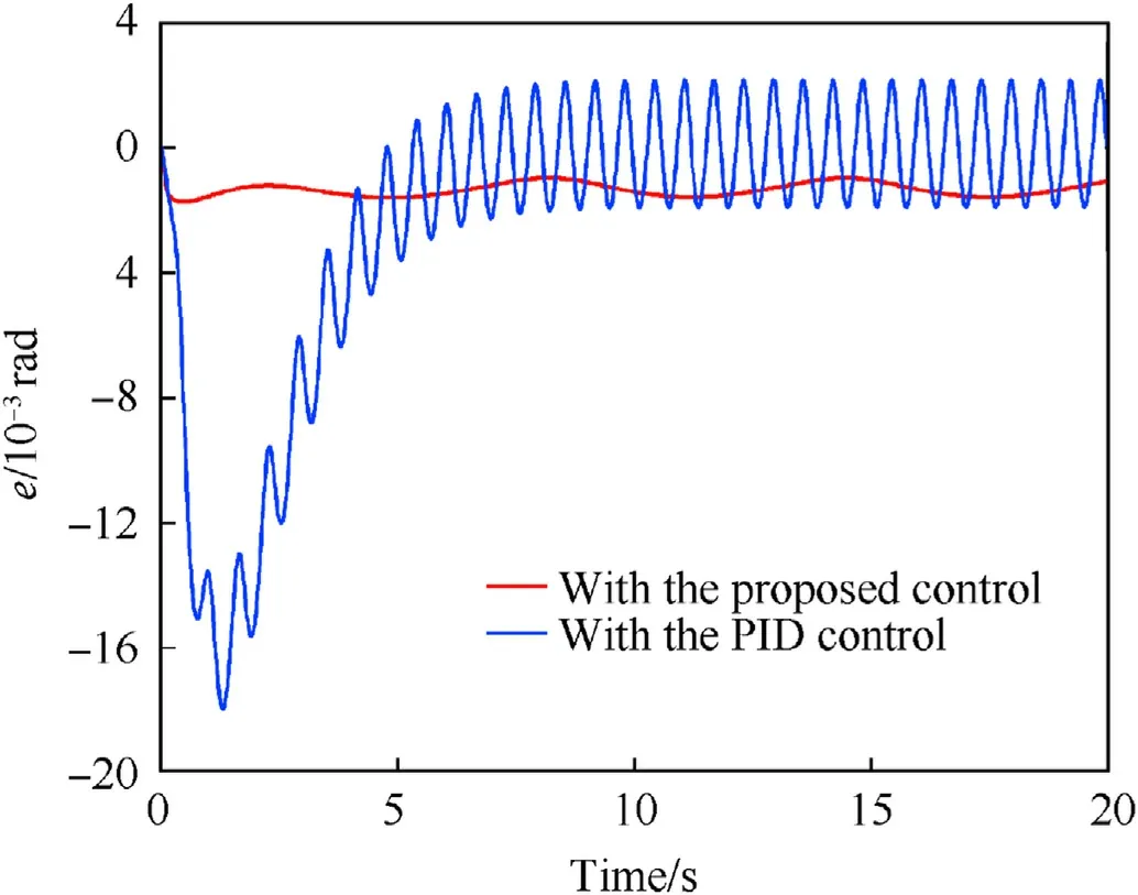
Fig.8.Comparative tracking error e in Case 2.

Fig.9.Comparative angular position θm in Case 2.

Fig.10.Comparative control input u in Case 2.

Fig.11.History of the adaptive law ˙^ε in Case 2.
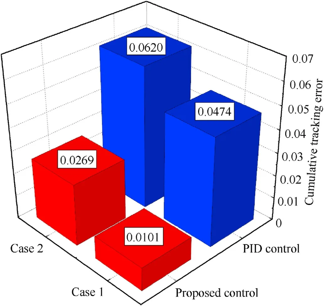
Fig.12.Comparison of the cumulative tracking error Ce.
Figs.5 and 9 present the dynamic comparison of the angular position in Case 1 and Case 2, respectively.From the simulation results, with the proposed control, both in Case 1 and Case 2, the angular position can always substantially stabilize around the desired angle.The angular position in Case 1 and Case 2 can also be stabilized with the PID control,but the convergence time is longer,the stabilization error is larger, and the control accuracy is poorer than the proposed control.
The control input in Case 1 and Case 2 are shown in Figs.6 and 10, respectively.From the simulation results, after the tracking error converge and stabilize near zero (i.e., after 4.5 s), the control input in Case 1 stabilize around a fixed value with the proposed control and the control input in Case 2 maintains a certain period of variation with the proposed control, which both means that the control input of Case 1 and Case 2 are presented in a stable state with the proposed control.
Figs.7 and 11 respectively show the history of the adaptive law in Case 1 and 2.From the simulation results, with the proposed control, after the tracking error converge and stabilize near zero(i.e., after 4.5 s), the adaptive law in Case 1 and Case 2 are both presented in a stable state,which demonstrates the effectiveness of the designed leaky adaptive law.
Fig.12 presents the comparison of the cumulative tracking errorCe.The value of cumulative tracking error is derived from the integration of the absolute value of the tracking error with respect to timet,which meansCe=∫t0|e(t)|dt.From the simulation results,the cumulative tracking error in Case 1 and Case 2 with the proposed control are both smaller than the error effect caused by the PID control.
6.Experimental validation
The proposed control strategy is implemented to the experimental platform of the vertical electric stabilization system to validate its feasibility and effectiveness under the practical physical condition.As shown in Fig.13, the experimental platform can realistically simulate the structure and movement of the vertical electric stabilization system, which is mainly composed of the mechanical part and the electric part.The mechanical part includes the upper carriage,the cradle,the barrel,the gun breech,the front bush, the rear bush, the spring damper and the electric cylinder.The electric part mainly includes an electrical cabinet, a dedicated workstation, an angle encoder to measure the angular position of the vertical electric stabilization system and a 150 MHz TMS320F28335 DSP.The DSP output signal analog to the driver of electric cylinder through D/A module, then the angle encoder measures the real-time angular position of the experimental platform and transmit the signal to the DSP in real time to complete the closed-loop control.The discretization C++codes are programmed to implement the proposed control and PID control.The sampling time of control is 2 ms.
The nominal system physical parameters of experimentalplatform are given in Table 4.The parameter uncertainty and uncertain nonlinearity are set asJm= 17.03+ 17.03 sintkg·m2,Beq=3.375×10⁻⁴+3.375×10⁻⁴sintN·m·s/rad,d1(t) =sint,d2(t) = sint,d3(t) = sint.Two different operating conditions are still considered in the experiment, besides, the PID control is still introduced as the comparison method.

Table 4Nominal system physical parameters of experimental platform.
Remark 5.According to the designed adaptive robust servo controller,it can be found that the velocity signals are necessary for the control implementation.Therefore,in the experiments,to avoid the effect of noise on the system tracking performance and stability,the velocity signals were achieved by measuring the one backward difference of the position signal, and then filtered with a secondorder Butterworth filter whose cutoff frequency is 10 Hz.The transfer function of the low-pass filter in the z-domain is [42].

Fig.13.Experimental platform of the vertical electric stabilization system.
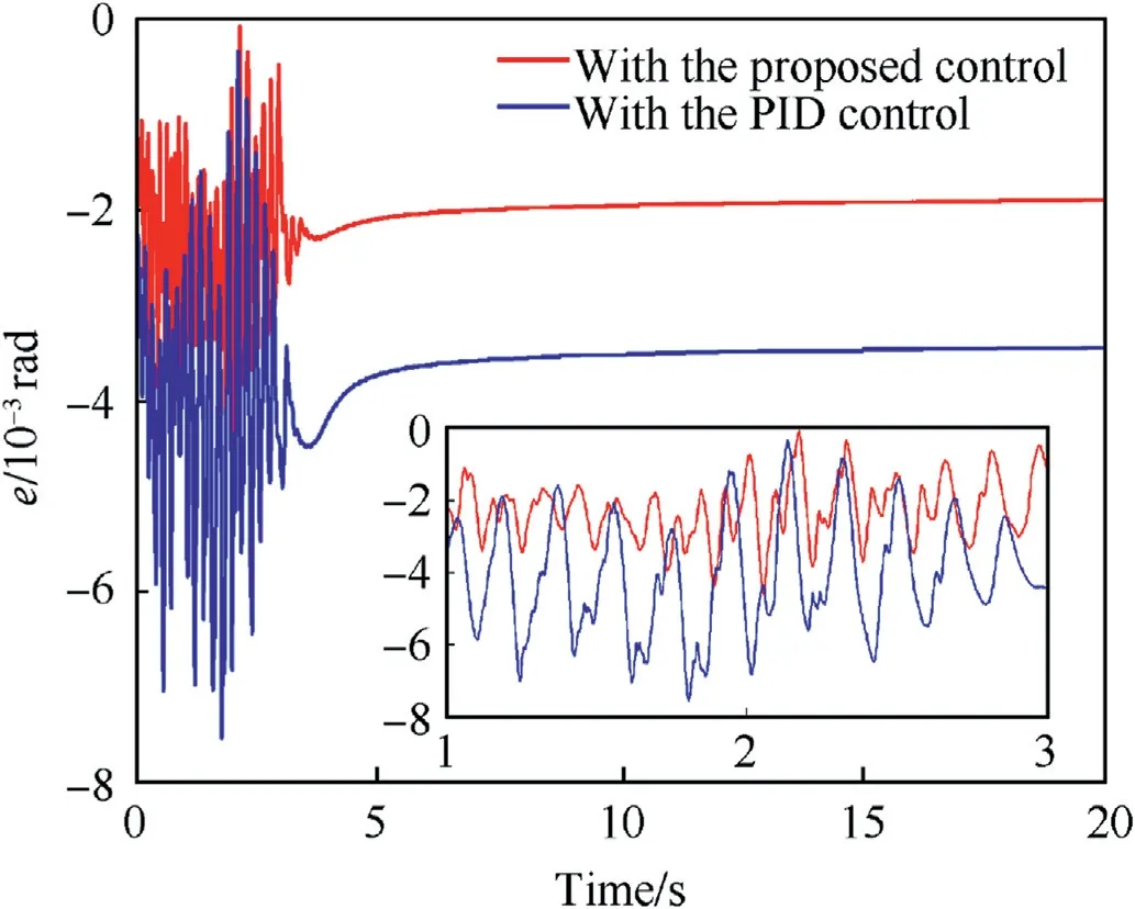
Fig.14.Comparative tracking error e in Case 1 of experiment.
In Case 1 of experiment,the desired reference command signal is set asrad to validate the steady-state tracking performance of the proposed control, the control parameters are set as γ = 5,α1= 1.5, α2= 0.5.Fig.14 presents the dynamic comparison of the tracking error in Case 1 of the experiment,it is not difficult to find that the tracking error can converge and stabilize near-0.002 rad after 4 s with the proposed control,while the tracking error can only stabilize near-0.004 rad after relatively longer time with the PID control.Besides, the fluctuation of the tracking error is relatively smaller with the proposed control.As shown in Fig.15, the angular position in Case 1 of experiment can always substantially stabilize around the desired angle with the proposed control comparing with the PID control,in addition to the stabilization error is smaller and the control accuracy is greater.Fig.16 show the history of the adaptive law in Case 1 of experiment.From the experiment results, with the proposed control, the adaptive law is presented in a stable state after the tracking error remains stable, which demonstrates the feasibility and effectiveness of the designed leaky adaptive law under the practical physical condition.
Remark 6.For ensuring the successful application of the proposed control method, the controller parameters need to be carefully selected.First,the controller parametersa1anda2are selected by theoretical derivation and numerical calculation to make the uncontrolled nominal system to be uniformly asymptotically stable at the origin.Second,in experiments,we carefully tune the control gains γ and α1, then slowly increase the control gains γ and α1to obtain satisfactory system effects, and then appropriately increase the values of α2to better handle system uncertainties and obtain better tracking performance.
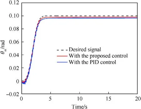
Fig.15.Comparative angular position θm in Case 1 of experiment.
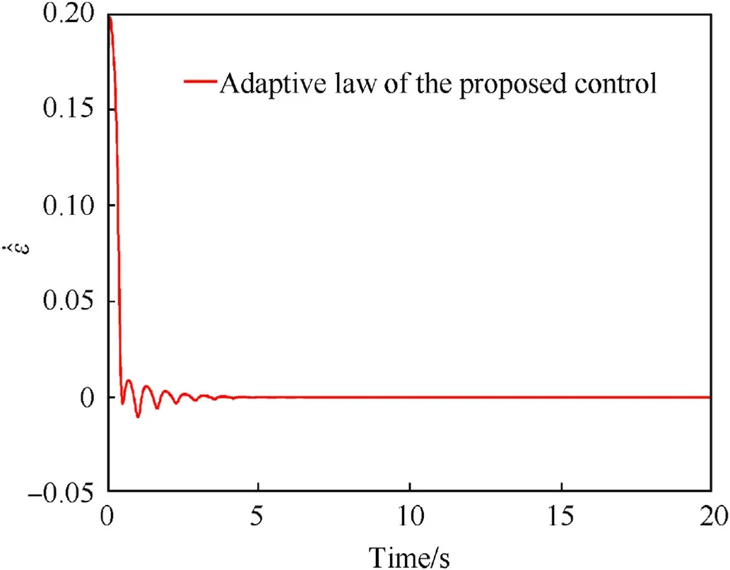
Fig.16.History of the adaptive law ˙^ε in Case 1 of experiment.
In Case 2 of experiment,the desired reference command signal is set as=0.1×sin(0.2πt)rad to validate the dynamic tracking performance of the proposed control, the control parameters are set as γ =1,α1=0.5,α2=0.1.Figs.17 and 18 respectively present the dynamic comparison of the tracking error and the angular position in Case 2 of experiment.From the experiment results, in the dynamic tracking process,the proposed control still has better tracking performance and stability performance compared to PID control.It is worth noting that, as shown in Fig.19, the designed adaptive law maintains certain frequency fluctuations around zero after the tracking error remains stable, which indicates that the uncertainty of the system also shows a complex trend during the dynamic tracking process.

Fig.17.Comparative tracking error e in Case 2 of experiment.

Fig.18.Comparative angular position θm in Case 2 of experiment.
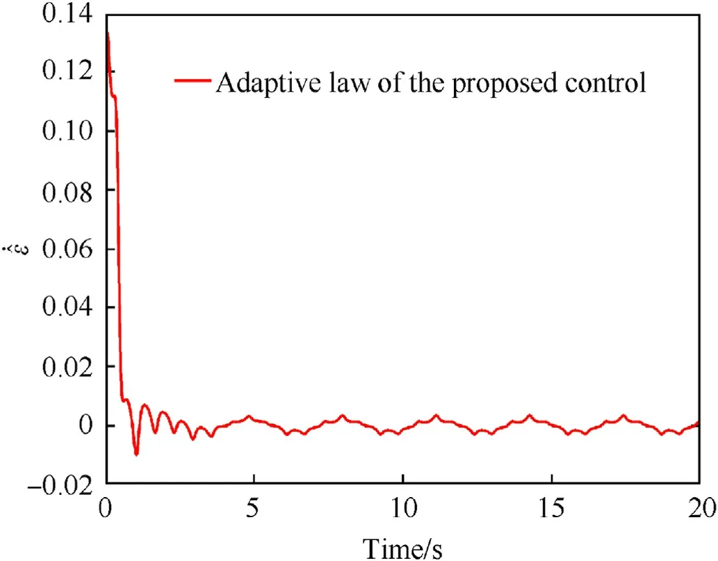
Fig.19.History of the adaptive law ˙^ε in Case 2 of experiment.
Through the above simulation and experiment results, it is not difficult to see that, compared with the traditional PID control method, the system nonlinearity, uncertainty and coupling can be better suppressed with the proposed control method, and the designed controller is still effective under the interference of various complex time-varying uncertainties (such as parameter uncertainty, uncertainty nonlinearity, etc.), which can ensure the vertical electric stabilization system to reach stability in a shorter period of time with higher stability accuracy.
7.Conclusions
To improve the tracking performance and stability of the vertical electric stabilization system of moving tank, an adaptive robust servo control strategy is proposed with the in-depth analysis of the complex nonlinearity and uncertainty inside the vertical electric stabilization system.The vertical electric stabilization system is firstly constructed as an uncertain nonlinear dynamic system,where the system uncertainty may be time-varying (fast) but bounded, and the bound is unknown.Secondly, an adaptive law is designed to evaluate the boundary of system uncertainty for overcoming the most conservative effects of uncertainty.Finally,for meeting the operational requirements of the fire control system,an adaptive robust servo control is proposed to maintain the tracking performance and stability of the vertical electric stabilization system.In this paper, the tracking stability problem of the vertical electric stabilization system is studied from a new perspective.Besides,the proposed control method is validated through the tests of the experimental platform, which provides new technical support for the application of advanced nonlinear control strategy on tank gun.As a future research topic, it is worthwhile to combine constraint-following control approach with adaptive robust control to solve the question of restricted control inputs.
Declaration of competing interest
The authors declare that they have no known competing financial interests or personal relationships that could have appeared to influence the work reported in this paper.
Acknowledgments
This work was supported in part by the Nation Natural Science Foundation of China under Grant No.52175099,China Postdoctoral Science Foundation under Grant No.2020M671494 and Jiangsu Planned Projects for Postdoctoral Research Funds under Grant No.2020Z179.
- Defence Technology的其它文章
- The interaction between a shaped charge jet and a single moving plate
- Machine learning for predicting the outcome of terminal ballistics events
- Fabrication and characterization of multi-scale coated boron powders with improved combustion performance: A brief review
- Experimental research on the launching system of auxiliary charge with filter cartridge structure
- Dependence of impact regime boundaries on the initial temperatures of projectiles and targets
- Experimental and numerical study of hypervelocity impact damage on composite overwrapped pressure vessels