
Quaternion-Based Adaptive Trajectory Tracking Control of a Rotor-Missile with Unknown Parameters Identification
2024-02-29 08:23JieZhaoZhongjiaoShiYuchenWangWeiWang
Defence Technology 2024年1期
Jie Zhao, Zhongjiao Shi, Yuchen Wang, Wei Wang
Beijing Institute of Technology, Beijing 100081, China
Keywords: Rotor-missile Adaptive control Parameter identification Quaternion control
ABSTRACT This paper investigates the adaptive trajectory tracking control problem and the unknown parameter identification problem of a class of rotor-missiles with parametric system uncertainties.First,considering the uncertainty of structural and aerodynamic parameters, the six-degree-of-freedom (6DoF) nonlinear equations describing the position and attitude dynamics of the rotor-missile are established,respectively,in the inertial and body-fixed reference frames.Next, a hierarchical adaptive trajectory tracking controller that can guarantee closed-loop stability is proposed according to the cascade characteristics of the 6DoF dynamics.Then, a memory-augmented update rule of unknown parameters is proposed by integrating all historical data of the regression matrix.As long as the finitely excited condition is satisfied,the precise identification of unknown parameters can be achieved.Finally, the validity of the proposed trajectory tracking controller and the parameter identification method is proved through Lyapunov stability theory and numerical simulations.
1.Introduction
The quadrotor is a class of low-altitude,slow-speed,and smallradar-cross-section (low-slow-small, LSS) unmanned aerial vehicles that can take off,land vertically,and hover in the air.Thanks to the rapid development of quadrotor UAV technology in recent years, it has been widely used in personal entertainment, security monitoring, disaster rescue, and other fields.With the unique configuration, the quadrotor can only rely on the four rotors to provide lift and forward thrust, resulting in low flying speed and poor maneuverability,which hinders its application in the military field.A missile or artillery projectile is a flight vehicle widely used in military combat.With the well-designed aerodynamic configuration,they can rely on the aerodynamic force/torque generated by the actuator to achieve large maneuvering during high-speed flight.However, it cannot hover in the air.
To alleviate the above contradictions, this paper developed a rotor-missile prototype that combines the take-off, landing, and hovering flight characteristics of the quadrotor UAV with the highspeed and large maneuvering flight characteristics of the missile.The aerodynamic configuration of the rotor-missile is illustrated in Fig.1.Four propellers are installed on the wings and mounted symmetrically around the fuselage.Tail-fins are installed at the rear of the body, together with the wings as the main aerodynamic surface.On the one hand, the propeller thrust can fully accelerate the rotor-missile to the maximum flying speed [1], while the aerodynamic force cancels out the gravity.On the other hand,when the flight speed is zero,the propeller thrust can provide lift to make the rotor-missile hover in the air.The hybrid configuration of the rotor-missile could render them dynamically unstable or unable to track a given trajectory.Therefore, it is necessary to design a trajectory tracking controller for the rotor-missile to ensure its flight stability and achieve accurate trajectory tracking.
Fig.1.Aerodynamic configuration of the rotor-missile.
Rotor missiles inherit the underactuated characteristics of quadrotor UAVs due to their similar structure [2].In addition, the aerodynamic force makes the dynamical equation describing the motion of the rotor-missile more complicated.As a result, the trajectory tracking problem of the rotor-missile is more challenging.For traditional quadrotor UAVs,either attitude stabilization control or position tracking control,or both have been extensively studied by many researchers.When the system parameters are perfectly known,the PID[3],LQR[4]controllers,and optimal control method[5] have proven effective in stabilizing the quadrotor near the hovering state.For complex maneuver flight profiles,linear control technology cannot handle nonlinear cross-coupling, and extensive nonlinear control methods are employed.Nonlinear feedback linearization schemes [6], back-stepping controllers [7], sliding mode control methods [8-10], and their combinations [11] are explored for trajectory or attitude control.However, in reality, the model’s parameters are usually not accurately obtained, and there is always uncertainty in the system.Robust control has been regarded as an effective method to deal with system uncertainty and disturbance since its inception [12].Since the worst-case should be considered, the closed-loop system is too conservative.Unlike robust control,adaptive control does not consider the worst case but adapts to the uncertainty of the system by adjusting the control gain in real-time.Model reference adaptive control[13]and L1adaptive control [14] have been employed in the quadrotor controller design.Various combinations of adaptive control techniques are used in the control of quadrotor UAVs.These methods include but are not limited to adaptive sliding mode control [15],adaptive fuzzy control [16], and adaptive neural network control[17].
The adaptive trajectory tracking control problem and the unknown parameter identification problem of a class of rotor-missiles with structural uncertainties (mass and moment of inertia) and aerodynamic uncertainties are addressed in this paper.The innovations and contributions of this paper can be summarized as the followings:
(1) Nonlinear six-degree-of-freedom dynamic equations with unknown parametric uncertainties are established for the rotor-missile.This model fully considers the nonlinear crosscoupling and aerodynamic force/moment.In addition, it is assumed that the mass, the moment of inertia, and aerodynamic coefficients are all unknown as parametric uncertainties.
(2) Considering that the dynamic model is a cascade and underactuated system, a hierarchical adaptive trajectory tracking controller is proposed to ensure the stability of the system and asymptotic tracking of the given position command.The proposed adaptive controller includes a position control layer, an intermediate coordination layer, and an attitude control layer.
(3) A memory-augmented parameter identification rule is developed to identify unknown parameters.In the parameter identification rule, the memory features (i.e., the integral of the regression matrix) are introduced into the traditional adaptive law to achieve the convergence of unknown parameters.
The remainder of this paper is organized as follows.Section 2 introduces the essential mathematical background used in this paper, including notations, terminology, and quaternion math.Section 3 establishes the 6-DoF nonlinear uncertainty model of the rotor-missile and formulates the problem to be solved.A hierarchical adaptive trajectory tracking controller equipped with a memory-augmented parameter identification rule is proposed in Section 4.Numerical simulations are conducted to evaluate the effectiveness of the proposed control method in Section 5.Section 6 concludes the whole paper.
2.Mathematical background
Notations and definitions used for later stability proofs are given as mathematical preliminaries in this section.For consistency reasons and the modeling of the attitude dynamics of a rotormissile, the basic algebraic concepts of quaternions are also presented.
2.1.Notations and preliminaries
Throughout the whole paper, we use H to denote the set of quaternions, Rn×mto denote the set ofn×1 real column vectors,Rn×mto denote the set ofn×mreal matrices, (·)to denote the transpose of a vector or a matrix, (·)-1to denote the inverse of a non-singular matrix or a quaternion,(·)*to denote the conjugation of a quaternion, λmin(·) to denote the minimum eigenvalues of a square matrix,‖·‖to denote the 2-norm of a vector or the norm of a quaternion, I to denote the identity matrix with proper dimension.
Given any vector a =[a1,a2,a3]∈R3,the notation[a]×denotes the following skew-symmetric matrix.
The persistently excited(PE)and finitely excited(FE)conditions are crucial for parameter convergence in adaptive control and system identification.The PE and FE conditions are defined as in Ref.[18].
Definition 1.(PE Condition).A bounded signal v(t)is persistently excited, if there existT>0 and γ >0 such that
Definition 2.(FE Condition).A bounded signal v(t) is finitely excited over a finite time interval[t,t+T], if there existT>0 and γ >0 such that
Remark 1.PE condition in Definition 1 and FE condition in Definition 2 are defined for vector signals and hold by a simple extension to matrices.
2.2.Quaternion math
Quaternions have been widely used to describe the rigid body attitude in aerospace fields such as quadrotor UAVs and satellites because they can avoid singularities and are simple to calculate.For the completeness of this article,some basic quaternion operations are introduced in this section to facilitate subsequent derivation.
A quaternion q∈H can be represented by a 4-dimension vector,which can be written as
whereqwis a scalar andis a 3-dimension vector.The conjugation,norm,and inverse of a quaternion q is defined by
The attitude of the rotor-missile is expressed in unit quaternions, so we have ‖q‖=1 and q-1= q*.
Given two quaternions,
the product,denoted by ⊗,can be defined as r =p⊗q This can be posed also in terms of the scalar and vector parts.
Noting that there are many ways to determine the quaternion,such as the Hamilton type [19] and the JPL type [20].For ease of implementation, this paper adopts the Hamilton-type quaternion to represent the attitude of the rotor missile, which is consistent with the quaternion module of the Eigen library.Given a global frame G and a local frame L ,the quaternion q and corresponding rotation matrix Rqtransform the vector xL(under local frame L )to xG(under global frame G) in the form of
where the rotation matrix Rqcan be calculated as
It is well known that although quaternions can avoid singularities, they can also cause sign ambiguity (also known as double cover).To avoid this,we only consider cases where the scalar part of the quaternion is positive, i.e., (0 ≤qw≤1).For a more comprehensive analysis and an in-depth description of quaternions, the reader is referred to Ref.[21].
3.Problem formulation
Dynamic models of different levels of complexity for quadrotor UAVs and missiles have been modeled and analyzed in numerous pieces of literature.However, no dynamic model can precisely define the dynamic behavior of the rotor-missile with a particular configuration and flight profile.In this part, with the help of existing dynamic models of quadrotor UAVs and missiles, we established the nonlinear uncertain 6-DOF equation of motion for the rotor missile.Moreover, we constructed the simultaneous control and identification problem to be solved in this paper.
The derivation of the dynamic model is roughly borrowed from the modeling process of quaternion-based rotor-crafts [22] and spinning missiles[23].Before developing the dynamical model,it is necessary to define reference frames used during the modeling process.Four reference frames, namely body-fixed frame B,desired body-fixed frame BD,intermediate body-fixed frame BM,and inertial frame I , are illustrated in Fig.2.
3.1.Rotational equations
Assuming that the moment of inertia of the rotor-missile is constant, and according to the law of conservation of momentum,the rotational dynamics equation can be expressed as
where Ib=diag(Ix,Iy,Iz)∈R3×3is a symmetric positive definite matrix representing the inertia tensor,represents the projection of the angular velocity of the rotor-missile in the body-fixed frame B, M∈R3represents the total moments acting on the rotor-missile, which can be expressed as
Defining the attitude unit quaternion of the rotor-missile as q,the rotational kinematics can be written as follows:
Fig.2.Conversion relationship between different reference frames.
3.2.Translational equations
Assuming that the mass of the rotor-missile is constant, and according to Newton’s second law, the translational dynamical equation is given as
wheremdenotes the total mass of the rotor-missile,denotes the velocity of the rotor-missile in the inertial frame I , Rqdenotes the rotation matrix that transforms the vector from the body-fixed frame B to the inertial frame I ,denotes the thrust vector in the body-fixed frame B,Tis the total thrust generated by four propellers,denotes the aerodynamic force acting on the rotor-missile in the body-fixed framedenotes the gravitational acceleration in the inertial frame I ,gis the gravitational constant.
Defining the position of the rotor-missile in the inertial frame I as, the translational kinematic equation can be represented as
Combining rotational .Eqs.(11) and (13) and translational Eqs.(15) and (16), we obtain the 6-DoF equations describing the spatial motion of the rotor-missile.If the aerodynamic force F and moment MAare ignored, the 6-DoF equations degenerate to the motion equations of a normal quadrotor.However, the aerodynamic force F and moment MAare crucial to the stable flight of the rotor-missile.In the next subsection, we calculate the aerodynamic force and moment according to the modeling process of the missile.
3.3.Aerodynamic force and moment
Considering that the rotor-missile does not rotate at a high rate,the Magnus force and moment can be ignored[24].For simplicity,only linear aerodynamic force and moment are considered.Defining the velocity of the rotor-missile in the body-fixed frame as, we have
The aerodynamic force F is mainly generated by the fuselage and the tail-fins,which can be considered as a linear function of vb,
Similarly, the aerodynamic moment MAcan be considered as
wherelrepresents the reference length,denote the derivative of the static moment coefficient to the corresponding angle, and,i=x,y,zrepresents the derivative of the damping moment coefficient with respect to the corresponding angular rate.Since the aerodynamic configuration is symmetric,andhold.Hence,the aerodynamic moment coefficient vector is, and the aerodynamic moment regression matrix as
3.4.Control objective
When the structural parameters and aerodynamic parameters are known,the dynamic model presented in Eqs.(11),(15),(18)and(19) represents the nominal dynamics of the rotor-missile.In reality, all or some of the parameters are unknown and are hard or expensive to obtain.For example,the massmand inertial tensor Ibof the rotor-missile may vary as the payload or the airframe change,resulting in deviations from its normal values.In addition, the aerodynamic coefficients cfand cmcan be obtained through computational fluid dynamics software or wind-tunnel tests,but it is easily perturbed in the flight period and deviates from the nominal values.
The underlying problem to be solved in this paper is to establish a control framework that enables the rotor-missile to track an ideal trajectory while simultaneously identifying unknown parameters in the presence of structural and aerodynamic uncertainties.
4.Main results
In this section, an adaptive controller with a memoryaugmented parameter identification rule is designed to achieve simultaneous control and identification.Considering that the dynamics model of the rotor-missile includes two parts: rotational dynamics and translational dynamics, the proposed adaptive controller adopts a hierarchical control framework, as shown in Fig.3.For the parameter identification rule, the integrals of regression matrices(i.e.,memory features)are augmented into the traditional update rule to force the adaptive gains to converge to the corresponding true values without PE conditions.
4.1.Position control
The position control loop is located at the top layer of the proposed adaptive control framework.It receives the desired position commands and outputs the desired thrust vector in the inertial reference frame.
With the input desired position vector pdand the measurable actual position vector p,we can define the position tracking error as
Similarly, the velocity tracking error can be computed as
where the desired velocity vector satisfies,leading to ve=.Before designing the position controller,we make the following assumptions on the desired trajectory position vector pd:
Assumption 1.We assume that the second-order derivative of the desired position vector exists and is bounded.This means that the desired position vector pd, its first-order derivativeand its second-order derivativeare all bounded.
The output of the position control module is the desired thrust vector Tdin the inertial frame I , which is defined as
To construct an adaptive controller for the position loop, the auxiliary linear velocity vais defined as
Fig.3.The structure of the hierarchical adaptive trajectory tracking controller.
where αpis a positive constant.Taking the derivative of the auxiliary linear velocity vato timet,and plugging in Eqs.(15)and(22),we have
which can be further simplified as
Since the massmand the aerodynamic coefficients cfof the rotor-missile are unknown, an adaptive controller with estimated parameters is proposed as follows:
wherekvandkpare positive constants, representing the velocity and position feedback gains,are, respectively, the estimations of the unknown parameters θv1, and θv2.
Remark 2.Noting that since the desired thrust vector Tdis contained in the regression matrix Yv1,the thrust vector Tdexpressed in Eq.(26) cannot be implemented in practical applications.By addingto both sides of Eq.(26)and then dividing both sides by 1+, we have
based on which, we can solve the desired thrust vector Td.
4.2.Desired orientation and control thrust
From the control framework in Fig.3,we can see that the middle layer of the adaptive controller generates the desired quaternion qdand the total thrustTbased on the output Tdof the position control loop.
The desired thrust vector Tdcan be represented as the product of magnitude and direction
where ‖Td‖ represents the magnitude of Tdand r is a unit vector calculated as
representing the direction of Td.
Due to the configuration of the rotor-missile, the total thrust is always along the axis xB.Therefore, to achieve accurate position tracking,thex-axis of the body-fixed frame B should point to the direction of the desired thrust vector,i.e.,xBaligned with r.For this purpose, we introduce the intermediate body-fixed system BM,thex-axis xMcoincides with r,they-axis yMlies in the horizontal plane and is orthogonal to xM,and thez-axis zMis determined by the right-hand rule.The geometric relationship between the inertial frame I and the intermediate body-fixed frame BMis shown in Fig.4.
Fig.4.Geometric sketch of the intermediate reference frame and inertial reference frame.
Define qmas the mismatch quaternion between the intermediate body-fixed frame BMand the inertial frame I .From Fig.4., we can define the normalized quaternion as
where ψ is the angle between xIand xM, u is the unit vector formed by the cross product of xIand xM.The following two cases should be considered while computing the mismatch quaternion qm:
Case I.xMcoincides with xI
In this case, the intermediate body-fixed frame BMcoincides with the inertial frame I ,that is r =xIand ψ =0,the mismatch quaternion is defined as
which means no rotation is performed.Hence,the angular velocity is zero and is defined as
Case II.xMand xIdo not coincide
In this case, the unit vector u can be calculated as
Then, substituting Eqs.(33) and (34) into Eq.(30), we have
where the derivative of the unit thrust vector is approximated by the high-pass filtered signal, that is,Sdenotes the Laplacian operator and τ denotes the time constant.
From the kinematics of quaternions, the augmented angular velocity of the intermediate body-fixed frame BMrelative to the inertial frame I can be calculated as
It is worth noting that even if xIcoincides with xM, the rotormissile can still rotate around the xMat any roll angle φdwithout changing the thrust direction.Define qφas the mismatch quaternion between the desired body-fixed frame BDand the intermediate body-fixed frame BM.According to the geometric relationship showed in Fig.4, the desired attitude quaternion qdcan be computed as
Once the desired orientation is obtained,the total control thrust can be expressed as
which means the total control thrust is along thex-axis of the desired orientation.
4.3.Attitude control
At the lowest layer of the proposed adaptive control framework is the attitude control loop.It calculates the control torque MTso that the attitude of the rotor-missile q can track the desired attitude qd, i.e., the body-fixed frame B align with the desired body-fixed frame BD.
To quantify the mismatch between the body-fixed frame B and the desired body-fixed frame BD, we define the rotation matrix Rqethat brings B onto BD.From Fig.2,we have two ways that can bring B onto BD: the first one is to go directly from B to BDthrough the rotation matrix Rqe,the second one is to go from B to I and then to BDthrough.Hence, the following equation holds
According to the relationship between the rotation matrix and the attitude quaternion defined in Eq.(9), we can define the quaternion tracking error qeas
where qesatisfies the following equations:
where ωerepresents the error angular velocity of B with respect to BDexpressed in B, which can be defined as
Defining the reference angular velocity ωras
where αqis a positive constant, and the auxiliary angular velocity ωaas
Taking the derivative of the auxiliary angular velocity ωato timet, an substituting in Eqs.(11) and (19), we have
where the derivative of the reference angular velocityto timetcan be expressed as
For compactness,Eq.(48) can be further simplified as
Since the inertia tensor Iband the aerodynamic moment coefficients cmof the rotor-missile are unknown,an adaptive attitude controller with estimated parameters is proposed as follows:
wherekω andkqare positive constants representing the angular velocity and attitude feedback gains,are,respectively, the estimation value of θω1,θω2, and θω3.
Remark 3.Note that since the control torque MTis coupled in the regression matrix Yω1, MTin Eq.(51) cannot be implemented in practical applications.Defining, we have
4.4.Parameter identification rule
In normal adaptive control, a gradient-based adaptive law is usually employed to ensure the stability and the tracking performance of the closed-loop system [23,25].However, the controller parameters do not converge to their corresponding nominal values unless the persistently excited condition in Definition 1 is satisfied[18], which is usually difficult to satisfy.To relax the restriction of the persistently excited condition of the regression matrix, concurrent learning based adaptive law is proposed to realize parameter convergence with only finite excited condition [26-28].Whereas,these methods require obtaining the derivative of system states, which is often difficult to measure.In addition, recording data selection algorithm are also necessary, resulting in the historical data not being fully utilized [29].In this subsection, an online memory-augmented parameter identification rule is presented to achieve system stability and parameter identification without requiring the derivative of system states and data selection algorithms.
Before designing the parameter identification rule,we make the following assumptions on the unknown parameters.
Assumption 2.We assume that all the unknown parameters are constants, that is, their derivatives are zeros.
Applying the position control law Eq.(26) into the auxiliary position subsystem Eq.(25), we can obtain the closed-loop auxiliary linear velocity dynamics as
Similarly, plugging the attitude control law Eq.(51) into the auxiliary attitude subsystem Eq.(50) yields
Defining the unknown parameter vector θ =[θv;θω],estimation parameter vector, regression matrix Y = diag(Yv,Yω),system states vector x =[va;ωa],velocity control gain matrix Kvel=diag(kvI,kωI), position control gain matrix Kpos= diag(kpI,kqI),and tracking error vector y = [pe;qev], Eqs.(53) and (55) can be rewritten as
For the identification of unknow parameters,the nominal value of Y(t)θ should be utilized.However, the time derivative of state x=[va;ωa] is necessary from Eq.(55), which is usually unmeasurable.A low-pass filter is commonly used to tackle this issue.Multiplying both sides of Eq.(55) by the impulse response of the filterh(t) =ce-ct.
wherec>0 denotes the time constant.
According to the rule of integration by parts,the second term on the right-hand side can be calculated as
Then, the filtered dynamics Eq.(56) can be simplified as
with ξ(0) = 0.
Defining memory features as the integral of filtered regression matrices,
the adaptive law is given as
where Γxand Γθare free designed positive definite symmetric matrices, denoting the adaptive gain.
Remark 4.In the implementation of position controller Eq.(27)and attitude controller Eq.(52),singularity will occur when1 and.Projection algorithm [30] could be applied in Eq.(63)to limit the update process to avoid singularity.
4.5.Stability analysis
In this subsection, the stability of the closed-loop system and the convergence of the identification error are analyzed by Lyapunov analysis method.
Consider a functionalVx, defined as
whose time derivative is given by
Substituting Eqs.(44),(53),(54)and(66)into Eq.(65),can be expanded as
Considering another functionalVθdefined as
whose time derivative is
The main result of this paper can be concluded as the following theorem.
Theorem 1.Considertheclosed-loopsystemconsistingofattitude dynamicsEqs.(11) and (13),positiondynamicsEqs (15) and (16),controlinputEqs.(26)and(51)andadaptivelawEq.(63).Then,the closed-loopsystemisstable, 、andallsignalsarebounded.And,thetrackingerrorspe, va, ωaandqevgoto0ast→∞.Moreover,ifthe regressionmatrixYHisfinitelyexcited,theestimatederrors~θgoto zeroasymptotically.
Proof: Define a candidate Lyapunov functional
withV>0,,andV(0,0,0,0,0) = 0.
Taking the derivative of Eq.(72), and substituting Eq.(69) and Eq.(71), we have
According to Definition 2,if YH(t)is not finitely excited,we have
Since min{αpkp,kv,αqkq,kω} is always positive, then ˙V≤0 and only when η1=0,the equality holds.Hence,we can conclude that the closed-loop system is stable,and tracking errors pe,va,ωaand qevgo to 0 ast→∞.From Eq.(23),it can be concluded that ve→0 ast→∞.Recalling that=1 and only considering the caseqew≥0,one hasqew→1 ast→∞,that is q→qdast→∞.Moreover,from Eq.(23), one has ωe→0 ast→∞.
If YH(t)is finitely excited,then there exists a timeTFEthat makes Y a positive definite matrix fort≥TFE.From Eq.(74), we have
According to the preceding analysis, it can be seen that the tracking errors will approach to zeros as the time goes to infinity.Moreover, the estimation error alsoast→∞.
Hence, we can conclude that the proposed adaptive controller with memory-augmented parameter identification rule can result in a stable closed-loop system and guarantee tracking errors, as well as the identification errors, approach to zeros as time goes to infinity.
5.Numerical simulation
In this section, the effectiveness of the proposed adaptive control framework is demonstrated by numerical simulation.All numerical simulation source codes are written in C++17,compiled by Apple clang 13.1.6 compiler,and runs on a 64-bit macOS 12.5 with Apple M1 Pro chip.In the source codes, the linear algebra library Eigen 3.4 is used for quaternion and matrix operations, and boost 1.80.0 is used for numerical integration.
The nominal values of physical parameters of the rotor-missile are given in Table 1.The massm, moment of inertiaIx,Iy,Izand aerodynamic coefficientsare unknown when designing the adaptive controller,and need to be estimated by the memory-augmented adaptive law.The nominal value of theunknown parameters can be calculated as θv1= - 0.9, θv2=.

Table 1Rotor-missile parameters.
Comparative numerical simulations with a fixed-gain controller and a normal adaptive controller are performed to illustrate the effectiveness of the proposed adaptive control framework.For the proposed adaptive controller, controller gains are presented in Table 2.In addition,the low-pass filter time constantcis set to 100.The adaptive gains are set as Γx=0.2Iand Γθ= 0.05I.For the normal adaptive controller, except for the memory-augmented adaptive gain Γθ= 0, other parameters are consistent with the proposed adaptive controller.For the fixed-gain controller,parameter adaption is not performed,so we set Γx=0 and Γθ=0,and other parameters are consistent with the proposed adaptive controller.
In the simulation,the initial estimation parameters are given as.And, the command trajectory and the command roll angle are given as functions of timet, pd(t) =where the command velocity vd, the command accelerationad, and the command roll ratecan be computed analytically.The initial position and velocity are set toand v(0) =.Moreover, the initial quaternion and angular rate are set toq(0)=.
Fig.5 shows the position tracking performances of the closedloop system with different controllers.It can be seen that the fixed-gain controller cannot achieve accurate position tracking in the presence of uncertainties, while both of the normal adaptive controller and the proposed adaptive controller can adjust the controller gains in real time to restore the tracking performance of the closed-loop system,see Table 3 for the quantized tracking error.
The output of different controllers,namely the total thrust T and the control torque vector MT, are illustrated in Figs.6 and 7.It can be seen that the output signals of the proposed adaptive controller is smoother than that of the conventional adaptive controller.This can be understood as the proposed adaptive controller possess better transient performance,that is,it can deal with uncertainties more gently.
The parameter convergence performance of two different adaptive controllers is given in Figs.8-12.Since the regression matrix Y does not meet the persistently exciting condition defined in Definition 1, the estimation values of the unknown parameters cannot converge to the corresponding nominal values.However,the proposed adaptive controller can guarantee the convergence of the estimation values.The memory-augmented adaptive law can relax the persistently exciting condition by integrating the regression matrix Y.As long as the regression matrix is finitely exciting during the simulation process, the identification objective can be achieved.
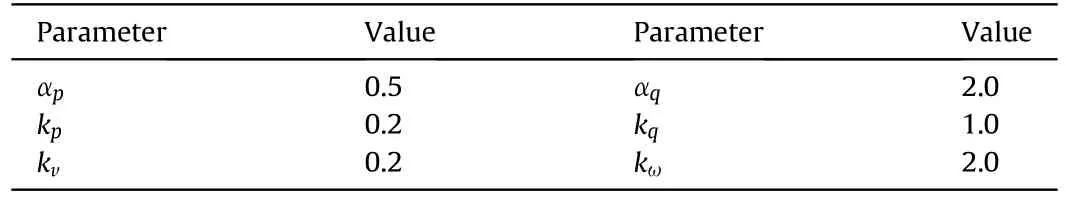
Table 2Control gains of the adaptive controller.
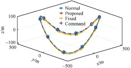
Fig.5.Tracking Performance of different controllers.
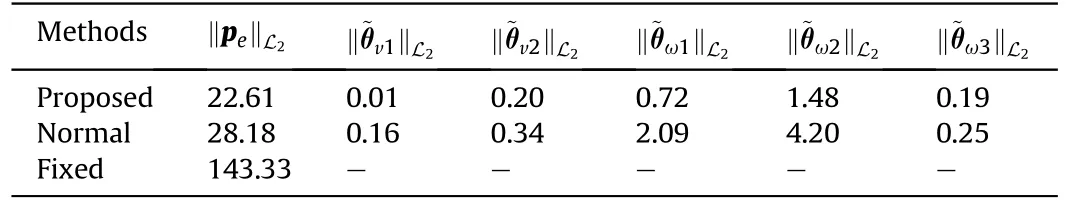
Table 3Quantized error comparison.
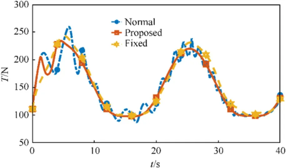
Fig.6.Total thrusts of different controllers.

Fig.7.Control torques of different controllers.
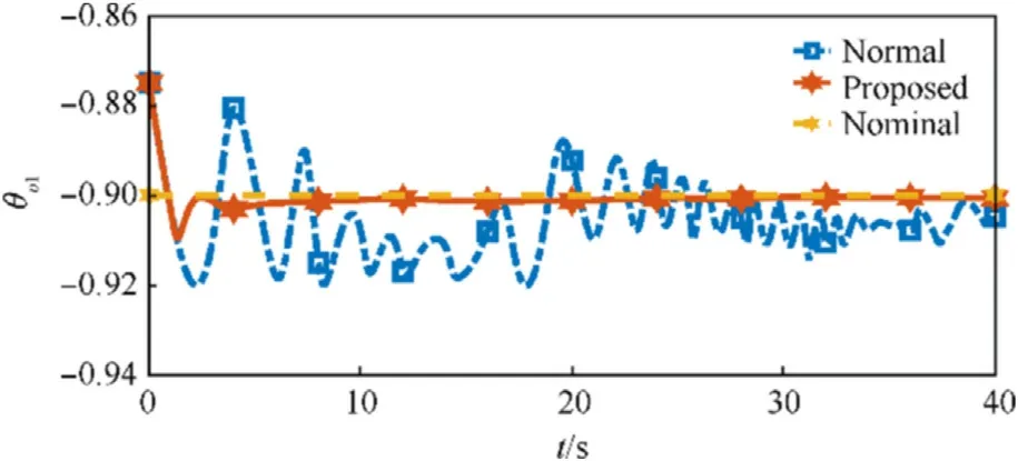
Fig.8.Converge performance of unknown parameter ^θv1
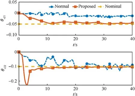
Fig.9.Converge performance of unknown parameter ^θv2
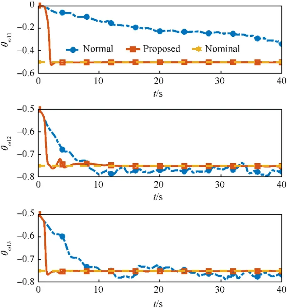
Fig.10.Converge performance of unknown parameter ^θω1

Fig.11.Converge performance of unknown parameter ^θω2
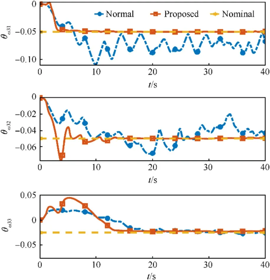
Fig.12.Converge performance of unknown parameter ^θω3
It can be concluded through numerical simulation that the proposed adaptive controller with memory-augmented adaptive law can not only ensure the stability of the closed-loop system in the presence of uncertainties, but also realize the identification of unknown parameters.
6.Conclusions
In this paper, the adaptive trajectory tracking problem and unknown parameter identification problem of a class of rotor-missiles are studied.A six-degree-of-freedom (6-DoF) dynamic model is developed by fully considering the aerodynamic force/moment generated by the fuselage and tail-fins and the control force/moment generated by four propellers.A hierarchical adaptive trajectory tracking controller is designed to achieve simultaneous control and identification by introducing the memory features into the parameter identification rule.A suitable Lyapunov functional is selected to prove that the proposed adaptive controller can ensure the stability of the closed-loop system and achieve accurate identification of unknown parameters.
Declaration of competing interest
The authors declare that they have no known competing financial interests or personal relationships that could have appeared to influence the work reported in this paper.
Acknowledgements
This Study was partially supported by the Natural Science Foundation of China(Grant Nos.62103052,52272358)and partially supported by the Beijing Institute of Technology Research Fund Program for Young Scholars.

- Defence Technology的其它文章
- The interaction between a shaped charge jet and a single moving plate
- Machine learning for predicting the outcome of terminal ballistics events
- Fabrication and characterization of multi-scale coated boron powders with improved combustion performance: A brief review
- Experimental research on the launching system of auxiliary charge with filter cartridge structure
- Dependence of impact regime boundaries on the initial temperatures of projectiles and targets
- Experimental and numerical study of hypervelocity impact damage on composite overwrapped pressure vessels