
Capillary Property of Entangled Porous Metallic Wire materials and Its Application in Fluid Buffers: Theoretical Analysis and Experimental Study
2024-02-29 08:23YuTngYiwnWuHuChengRongLiu
Defence Technology 2024年1期
Yu Tng , Yiwn Wu ,*, Hu Cheng ,b, Rong Liu
a Engineering Research Center for Metal Rubber, School of Mechanical Engineering and Automation, Fuzhou University, Fuzhou 350156, China
b AECC Guizhou Liyang Aviation Power Co., LTD, Guiyang 550014, China
c College of Computer and Information Sciences, Fujian Agriculture and Forestry University, Fuzhou 350156, China
Keywords: Entangled porous metallic wire materials Capillary property Viscous fluid Low-speed impact Damping force
ABSTRACT Strong impact does serious harm to the military industries so it is necessary to choose reasonable cushioning material and design effective buffers to prevent the impact of equipment.Based on the capillary property entangled porous metallic wire materials(EPMWM),this paper designed a composite buffer which uses EPMWM and viscous fluid as cushioning materials under the low-speed impact of the recoil force device of weapon equipment (such as artillery, mortar, etc.).Combined with the capillary model, porosity, hydraulic diameter, maximum pore diameter and pore distribution were used to characterize the pore structure characteristics of EPMWM.The calculation model of the damping force of the composite buffer was established.The low-speed impact test of the composite buffer was conducted.The parameters of the buffer under low-speed impact were identified according to the model, and the nonlinear model of damping force was obtained.The test results show that the composite buffer with EPMWM and viscous fluid can absorb the impact energy from the recoil movement effectively, and provide a new method for the buffer design of weapon equipment (such as artillery, mortar, etc.).
1.Introduction
Impact is widespread in the military field.If the impact reaches a certain energy level,it will cause damage to weapon equipment.With the development of science and technology, more precise instruments have higher requirements for impact prevention.Therefore,it is necessary to reasonably select cushioning materials and design efficient buffers to dissipate impact energy to protect equipment.Nowadays,according to the effective working times of the buffer materials, it can be divided into disposable impact buffers and repeatable impact buffers.
The main forms of energy absorption of disposable impact buffers are plastic deformation of ductile metals (such as bending collapse, puncture, tube expansion, necking, overturning, tearing and the combination of the above [1,2]), internal friction of materials [3], crushing/debonding/penetration of composite filler and matrix [2], buckling of cellular materials [4], and water wall vaporization to absorb explosive energy[5].The disposable impact buffer is applied to helmets,car bodies,helicopter landing gear and bridges[6,7].Repeatable impact buffers can be divided into metal,rubber, fluid, and composite.Metal buffer materials include metal spring,steel wire rope,EPMWM,which generate large deformation and energy consumption behavior through sliding and friction in the form of compression and shear[8].Due to the internal damping of the rubber material, the vibration isolation and buffering effect on the high frequency band is realized under compression or shear stress.However,due to its inherent characteristics,it is sensitive to high and low temperatures and corrosive environments [9].Fluid can be divided into gas, liquid, electro/magnetorheological fluid and other buffer media.Traditional gas and liquid media absorb impact energy due to their own compressibility, viscous friction,friction loss and other damping mechanisms,but they are harsh to the sealing environment and have poor environmental adaptability[10,11].Because of its high yield stress,strong durability,low input current and voltage, the electro/magnetorheological fluid is also used as a cushioning material to design the buffer [12,13].It has been widely used in helicopter landing gear [14], seat suspension anti-collision devices [15] and weapon (guns, artillery, etc.) antirecoil devices [16].However, the problem of stability and life of electro/magnetorheological fluids still exists.Because a single cushioning material has some drawbacks that are difficult to eliminate, researchers have developed various composite buffers according to application requirements.There are many kinds of composite buffers.According to the component composition,there are all metal composite buffers, such as EPMWM-metal spring composite buffer, wire rope-metal spring damper, etc; There are rubber materials that provide high damping buffers, such as rubber-steel wire rope composite buffers, shape memory alloy filled rubber bearings [17], EPMWM-rubber composite laminated energy dissipators, etc; There are also fluid buffers (viscous fluid,magnetorheological fluid, etc.) that provide damping and energy dissipation composite buffers, such as steel wire ropemagnetorheological damper, disc spring-fluid composite buffer[18], string mesh structure buffer with parallel fluid dampers [19],and composite buffer with porous metal foam and magnetorheological fluid [20], such as the designed three parameter fluid buffer [21] used to suppress micro vibration generated by satellite structures.
EPMWM is a kind of winding metal mesh material prepared by winding (or weaving, laying), cold stamping molding, posttreatment and other processes of metal wire spiral coil [22].Due to the complex wire turn space in EPMWM, the motion of extrusion,sliding and friction between metal wires can dissipate impact energy when being compressed.Therefore,metal rubber is widely used in vibration reduction[23,24]and impact resistance[25-27].Although EPMWM is formed by cold stamping and compressed from a loose blank to a compact specimen,the gap between wires still exists and presents capillary characteristics,so EPMWM is also used for filtering and throttling in engineering [28-30].Bai et al.[31] considered that EPMWM had excellent pore connectivity characteristics and was suitable for fluid throttling and pressure regulating devices.Guo et al.explored the difference between the shape(annular and cylindrical)of EPMWM[32],the combined type and the integral type in filtering and throttling performance [33],and introduced the capillary model to study the filtering accuracy[34].All the above researches provide the basis and experience for the design of the composite buffer.
Based on the capillary property entangled porous metallic wire materials(EPMWM),this paper designed a composite buffer which uses EPMWM and viscous fluid as cushioning materials under the low-speed impact of the recoil force device of weapon equipment(such as artillery,mortar,etc.).A variety of parameters were used to characterize the pore structure characteristics of EPMWM.The calculation model of damping force was established.The low-speed impact test of the composite buffer was conducted.The parameters of the buffer under low-speed impact were identified according to the model,and the nonlinear model of damping force was obtained.
2.EPMWM preparation and composite buffer design
2.1.EPMWM specimen
EPMWM can be prepared by the classical four-step method(Fig.1) [35].The manufacturing process is as follows: (1) The appropriate metal wire is selected as the raw material according to the use demand, and the raw wire is wound into a dense spiral winding with a specific spiral diameter by a spiral winding device;(2) The stretched spiral coil is wound on the mandrel to make the blank;(3)The blank is put into a special mold for molding;(4)The EPMWM specimen can be obtained after post-processing (such as cleaning and heat treatment) of the molded samples according to the requirements.Considering the special working environment of EPMWM, the austenitic 304 stainless steel with good mechanical properties and practical use is generally used to prepare EPMWM specimens [27].The main chemical components are shown in Table 1.
Table 2 shows the EPMWM specimens with different porosityand wire diameters.Some EPMWM specimens are shown in Fig.2.Selection of appropriate EPMWM density is the key to impact resistance.This can ensure that after impact, the EPMWM specimen will not have plastic deformation due to low density,nor will the EPMWM rigidity be too large due to excessive density.A scanning electron microscope (SEM) is used to observe the microstructure of the EPMWM specimen, as shown in Fig.3.
Table 1Chemical compositions (wt%) of the raw wires used.

Fig.1.Preparation of EPMWM specimen.

Table 2Preparation parameters of EPMWM specimens.
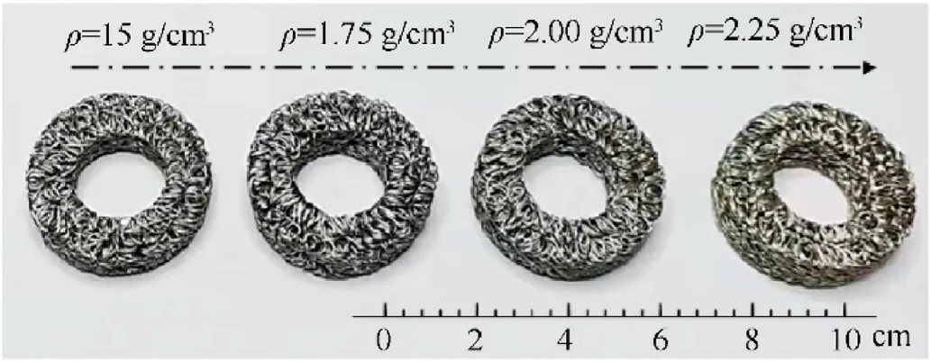
Fig.2.EPMWM specimens with different densities.
It can be seen from Fig.3 that the pore distribution of EPMWM is relatively uniform, and it has the characteristics of an excellent throttling element.
2.2.A composite buffer with EPMWM and viscous fluid

Fig.3.SEM of EPMWM specimens (2.00 g/cm3).
To study the capillary property of EPMWM, a composite buffer with EPMWM and viscous fluid was designed.Its main components were: cylinder block, cylinder head, piston and piston rod, baffle,seal ring, and guide ring, as shown in Fig.4.The specification of damping holes was 6 × φ8 mm, and the other two specifications were 4 × φ8 mm, 6 × φ6 mm.The geometric and material parameters of the test prototype are shown in Table 3.
Industrial grade dimethyl silicone oil from American Dow Corning company was selected as viscous fluid damping material(kinematic viscosity is in mm2/s or centistokes(cSt),1 cSt=1 mm2/s).Compared with ordinary hydraulic oil,its viscosity range is large,and it is applicable to the scene where the working environment temperature changes greatly.
When the buffer piston rod is excited by impact or vibration,the piston moves in the buffer, the oil pressure in one chamber increases, and the oil pressure in the other chamber decreases.The differential pressure forces the viscous fluid to flow through the zigzag passage of EPMWM in the piston, squeezing the EPMWM installed on the piston,and pushing the high-pressure oil to flow to another pressure chamber.If the pressure drop of EPMWM is large,the damping force and stiffness of the buffer is large;If the stiffness of EPMWM is very small, and its pressure drop is very small, the damping force of the buffer is also small.Therefore,the parameters of EPMWM play an important role in the damping force characteristics of the composite buffer.
3.Analysis of the pore structure characteristics of EPMWM
In this paper, porosity, hydraulic diameter and maximum pore diameter were used to characterize the pore structure characteristics.
3.1.Porosity
All pores of EPMWM are completely connected,and its porosity can be defined as the ratio of pore space volume to the total volume of material [36].
whereVpis the volume occupied by pores in porous materials,Vtis the overall volume of porous material,Vsis the volume of solid skeleton in porous materials,mEPMWMis the mass of metal wire constituting EPMWM,VEPMWMis the overall volume of EPMWM,ρ is the density of metal wire.
3.2.Hydraulic diameter

Fig.4.Structural diagram of composite buffer with EPMWM and viscous fluid.

Table 3Main structural parameters of the test prototype.
According to Garman Kozeny theory, even if the shape of the capillary channels and cross sections in porous media is extremely complex, the curved non-circular pipeline channels in porous structures can be assumed to be straight capillary pipeline channels with constant cross section and circular shape, and the damping force model can be established based on the hydrodynamic theory of straight circular pipeline channels [29].According to the test method established by fluid mechanics, it is assumed that the channel diameter (also called hydraulic diameterDHor equivalent diameterde)controlling the flow through the pipeline channels is 4 times of the hydraulic radius.The wetting perimeter χ is the perimeter of the solid wall contacting the fluid on the flow cross section of the total flow of the pipeline channels,and the hydraulic radius is the ratio of the area of the pores on the flow cross section to the wetting perimeter χ.Therefore, the expression of hydraulic diameterDHis
whereAis the total area of pores on the flow cross section,χ is the total wetting perimeter on the flow cross section.
The expression of hydraulic diameterDHof EPMWM is
whereApis the area occupied by pores on the cross section of EPMWM, ε is the porosity of EPMWM, D is the diameter of EPMWM.
For EPMWM,according to Eq.(3),its hydraulic diameter can also be expressed as
whereVpis the volume occupied by pores in EPMWM,Spis the sum of surface areas of all pores in EPMWM.
VpandSpcan be expressed by the diameter, total length and porosity of their wire materials.
whereVwis the volume of metal wire in EPMWM,dwis the diameter of the wire,lwis the total length of the wire.
Substitute Eqs.(5) and (6) into Eq.(4), and the hydraulic diameterDHof EPMWM can be obtained as
It can be seen from Eq.(7) that the hydraulic diameterDHof EPMWM is related to its porosity and the diameter of the metal wire material.
3.3.Maximum pore diameter
The maximum pore diameter significantly affects the permeability and other hydrodynamic properties of porous materials.The shape and size of the internal pores of EPMWM are different and disordered,which cannot accurately describe their porous characteristics.Therefore, the theoretical formula of the maximum pore diameter of EPMWM can be established based on the capillary model and Rayleigh distribution method.
Assuming that the distribution density of the porous material isf(d), and the porous material containsNchannels per unit area.Based on the isotropic capillary model [30], the porosity of the porous material is
wheredis the pore size,f(d)ddis the relative number of pore sizedtod+dd,α'is the bending coefficient of the actual flow passage in the porous material relative to the straight passage.
If there areNchannels on the cross section of EPMWM of unit area,the porosity of EPMWM can also be expressed as:
wheredaveis the average pore diameter of EPMWM.
The research shows that the average pore diameter of EPMWM can be equivalent to its hydraulic diameter[36].Substituting Eq.(7)into Eq.(9), the number of pore channels on the cross section of EPMWM per unit area can be obtained as follows:
Based on Rayleigh distribution,the maximum pore diameter of EPMWM can be obtained.
where σkis the standard deviation of pore diameter edge distribution, μ is the position parameter of pore diameter edge distribution.
Substitute Eqs.(10) and (11) into Eq.(8) to obtain
Import parameters λ and γ,
By substituting parameters, the equation can get
It can be further expressed as
Import parameterI1, setu=λ2/2, then,
Import parameterI3, setw=λ2, then dw= 2λdλ,
According to the cumulative distribution function of Rayleigh distribution, when= 0.9973, that is, the probability is 0.9973,dmax= 6.88σk, γ = 3.44, φ(3.44)=0.4997 can be obtained.Substituting the above data into Eq.(20), the maximum pore diameter can be obtained as follows:
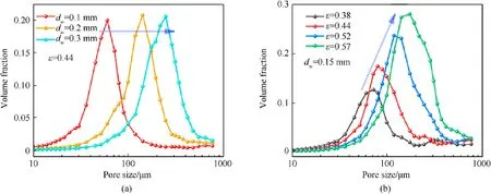
Fig.5.Pore size distribution of EPMWM: (a) Different wire diameters; (b) Different porosity.
3.4.Pore size distribution characteristics of EPMWM
The pore size distribution characteristics of EPMWM were studied according to the mercury intrusion method.The prepared EPMWM specimens (Table 2) were measured with AutoPore IV 9500 automatic mercury intrusion instrument.The test results are shown in Fig.5.
To verify the correctness of the theory for the pore size distribution, the test results were compared with the theoretical calculation value of Eq.(7).The relationship between the hydraulic diameter, wire diameter and porosity is shown in Tables 4 and 5 respectively.The error between the theoretical value and the test value of the hydraulic diameter is within 5%, which verifies the reliability of the theoretical calculation equation.When the porosity is 0.44 and the wire diameter is 0.1 mm, 0.2 mm and 0.3 mm respectively, the hydraulic diameter of EPMWM increased with the increase of its wire diameter(Table 4).It can be seen from Fig.5(a) that when the porosity was a fixed value, the hydraulic diameter of EPMWM with different wire diameters accounted for almost the same proportion.When the wire diameter was 0.15 mm and the porosity was 0.38, 0.44, 0.52 and 0.57 respectively, the hydraulic diameter of EPMWM increased linearly with its porosity(Table 5).It can be seen from Fig.5(b)that when the wire diameter was a fixed value,the proportion of hydraulic diameter of EPMWM with different porosity increased with the increase of porosity.

Table 4Relationship between hydraulic diameter and wire diameter of EPMWM.
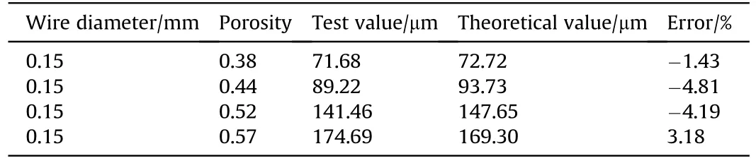
Table 5Relationship between hydraulic diameter and porosity of EPMWM.
4.Damping force model of the composite buffer with EPMWM and viscous fluid
For EPMWM, previous experimental studies have shown that the critical Reynolds number Rec is 28 [30].In addition, the kinematic viscosity of the fluid medium in this paper is greater than 1000 cSt,and the length of the capillary pore is more than 10 times of the pipe diameter [37].Therefore, the local energy loss of the fluid in EPMWM can be ignored.
The damping force model of the composite buffer with EPMWM and viscous fluid was established.The working space of the buffer cylinder body mainly included a compression chamber, a rebound chamber, a piston rod, a cylinder block, a piston and an EPMWM specimen, as shown in Fig.6.
As shown in Fig.6, when the piston moves from right to left(compression condition) in the cylinder block, the pressure in the compression chamber increases and the pressure in the rebound chamber decreases,which forms a pressure difference at both ends of the piston (Δp = p3- p1).Under the function of this pressure difference,the high-pressure oil in the compression chamber flows through the piston.Due to the restriction of the damping hole and EPMWM in the piston(p2),the oil pressure drops a part.In addition,in order to flow to the rebound chamber,the viscous fluid extrudes the metal wires and internal pores in the EPMWM specimens.This action also occurs when the piston moves to the right (rebound condition).
According to non-Newtonian fluid mechanics, the energy loss along the way when the fluid flows through the straight pipe is calculated[38,39].The equation of motion of non-Newtonian fluid in a circular pipe along the pipe lengthzis
No, said the man; what should I have wished from him? Ah! said the woman, it s dreadful to have to live all one s life in this hut that is so small and dirty; you ought to have wished for a cottage
Whenr=Rat the pipe wall, the shear stress is
For shear thinning and shear thickening fluids,power law can be used to express their rheological equations [40], then

Fig.6.The working space of the buffer cylinder body.
wherekis the dynamic viscosity of the fluid,mis the fluid flow index.
Substitute Eq.(23) into Eq.(25).
Separate variables and integrate with Eq.(26) to obtain
Further, the flow expression can be obtained.
Assuming that the diameter of the circular straight pore isdand the length of the pore isl, the average flow velocity of the fluid in the damping pore is
It can be seen from Eq.(2)that the hydraulic radiusRHof circular section orifice isRH=A/χ = πR2/2πR=R/2, that is, the radius of circular section damping orifice isR= 2RH, and the diameter isd= 4RH.Substitute the above equation into Eq.(30).
It can be seen from the above section that the hydraulic diameterDHof EPMWM isdwε/(1-ε).Then the hydraulic radiusRHof EPMWM is
According to the fluid continuity equation[41],the relationship between the motion velocityVof piston and the average velocityvof fluid flowing in EPMWM is as follows:
whereA1is the effective area of the pistonA2ε),A2is the cross section of damping pores.
Substitute Eqs.(31) and (32) into Eq.(33) to get
According to the relationship between the pressure ΔPand the damping forceFin the fluid buffer is ΔP=F/A1,the damping force generated by the energy loss along the buffer can be obtained:
The damping force is expressed as
where the viscosity coefficientcis
Due to the shear thinning phenomenon of elastic cement(dimethyl silicone oil) in the buffer, the flow indexmin its constitutive equation changes with the impact speed, and the viscosity coefficientcalso changes.
5.Mechanical property test under low-speed impact
To study the cushioning performance of the composite buffer with EPMWM and viscous fluid under low-speed impact load, a drop hammer impact test system was used to conduct low-speed impact test.The effects of the viscosity of viscous fluid, the number and specification of damping holes, and the porosity of EPMWM on the dynamic characteristics of the composite buffers were investigated.
5.1.Low-speed impact test
5.1.1.Testequipmentandmethod
The low-speed impact test with self-designed drop hammer device was conducted [42], as shown in Fig.7.The device was composed of dynamic force sensor, displacement sensor, data acquisition system, control system, drop hammer, lifting and release mechanism.The data acquisition and control were mainly completed by LabVIEW RT and X series data acquisition boards(NI,PCIe-6351).The lifting and releasing mechanism was used to lift and release the drop hammer respectively.The impact force and deformation of the buffer were measured by dynamic force sensor and magnetic sensor respectively.
As shown in Fig.7, the displacement sensor in the test equipment collects the displacement signal at a unit time interval,so the speed of the hammer in the process of impact motion can be obtained through the collected displacement data and time pulses.The speed can be expressed as
The natural fall of the hammer converts gravitational potential energy into kinetic energy.It is assumed that only gravitational potential energy and kinetic energy are being converted.According to the energy conservation law,the work done by gravity is equal to kinetic energy, and is converted into impact energy during impact process.Therefore, the impact energyEcan be defined as
wheremis the mass of the hammer(m= 76 kg),gis the acceleration of gravity,his the height of free fall of the hammer before impact, andv0is the impact speed of the hammer when it falls to impact the buffer.
Table 6Test settings of low-speed impact test.
5.1.2.Testcondition
The single factor control variable method was used to set up four test control groups,including fluid viscosity,number and hole size of damping holes, porosity of EPMWM, and impact velocity.The influence of each parameter on the cushioning performance of the composite buffer with EPMWM and viscous fluid was studied respectively.The test settings are shown in Table 6.Impact tests are generally divided into low-speed (<10 m/s), medium-speed(10-50 m/s), and high-speed (50-1000 m/s) impacts [43,44].In this paper, the focus was on low-speed impact, which mainly corresponded to the buffer used in recoil devices impact.In the existing Ref.[42], EPMWM has excellent repeated energy absorption capacity, and the mechanical properties (energy absorption rate and impact stiffness)of EPMWM is stable.And the appearance and shape have no obvious damage under repeated impact.EPMWM can still exert good damping performance and maintain good pore characteristics.Therefore,this test took single impact as the test condition.The impact working condition of the composite buffer is shown in Table 7.

Fig.7.Test equipment of low-speed impact test.
5.2.Test results and analysis
Fig.8 shows the composite buffer (EPMWM with a density of 1.5 g/cm3,dimethyl silicone oil with a fluid viscosity of 1×10⁵cSt,and damping holes with a specification of 6 × φ8 mm)displacement-time and velocity-time under condition 1(V0= 2.5 m/s).It can be seen from Fig.8(a) that the displacement dropped after reaching the maximum value, which indicated that the impact hammer rebounded slightly after the end of the piston rod stroke.The rebound velocity of the impact hammer can be observed from Fig.8(b).
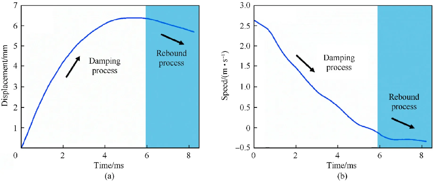
Fig.8.The typical response of the composite buffer under low-speed impact: (a) Displacement-time curve; (b) Speed-time curve.
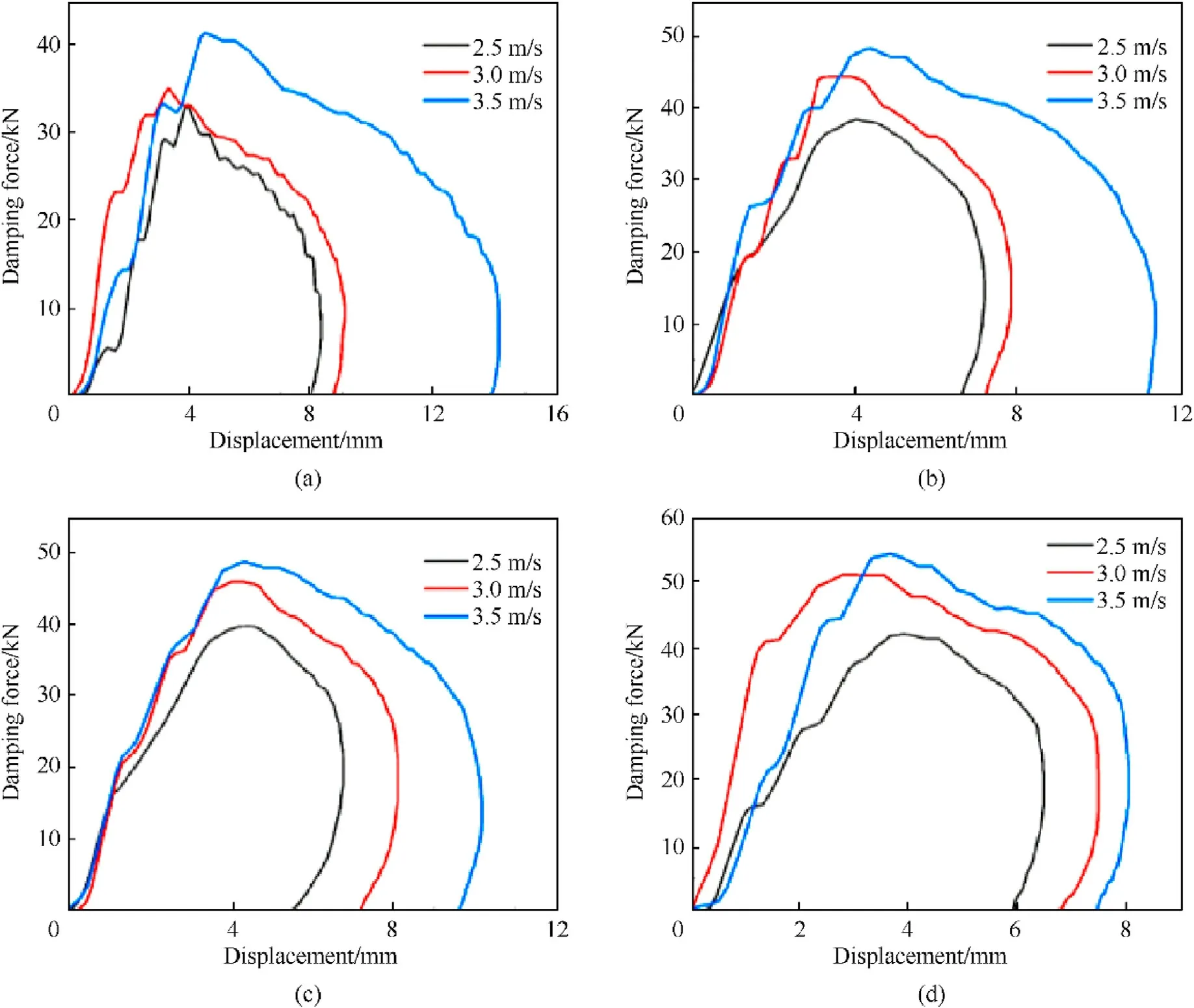
Fig.9.Damping force-displacement curve under three impact working conditions: (a) ρ = 1.5 g/cm3; (b) ρ = 1.75 g/cm3; (c) ρ = 2.00 g/cm3; (c) ρ = 2.25 g/cm3.
5.2.1.EffectofEPMWMwithdensityontheperformanceofthe compositebuffer
EPMWM is the main factor affecting the mechanical properties of the composite buffer.The influence of density on the mechanical properties of the composite buffer was studied below.EPMWM with different densities (1.5, 1.75, 2.00 and 2.25 g/cm3), and dimethyl silicone oil with fluid viscosity of 1×10⁵cSt,and damping hole size of 6 × φ8 mm were selected.
The damping force-displacement and damping force-velocity curves of four composite buffers with different EPMWM densities(1.5,1.75, 2.00 and 2.25 g/cm3) under three impact working conditions are shown in Figs.9 and 10 respectively.
During the impact process, the damping force of the drop hammer increased from zero to the maximum value when it started to contact the piston rod until it completely collided with it(Fig.9(a)).Then the piston rod moved simultaneously under the impact load of the drop hammer, where the damping forcedisplacement curve showed a stable and gentle decline phase,and the piston stroke gradually increased.While the velocity of the drop hammer gradually decreased under the effect of the damping force of the composite buffer (Fig.10(a)), until the velocity decreased to zero,the piston stroke reached the maximum value,at which time the damping force decreased to zero.
In Fig.9(a), before the gentle stage of the damping forcedisplacement curve under different impact working conditions,there was a change phenomenon of increased fluctuation.There was no unified explanation for this change phenomenon: One explanation was that the filtering processing failed to completely eliminate the interference caused by the rigid collision between the impact hammer and the piston rod;Another explanation was that when the impact hammer collided with the piston rod,the viscous fluid did not flowed at this moment,while the piston in the buffer had a relative displacement,which had a compression effect on the viscous fluid in the compression chamber as shown in Fig.4.The damping force in the above changes was the elastic damping force generated by the compression of EPMWM and the shear damping force generated by the instantaneous flow.
In the test of the same composite buffer, with the increase of impact velocity, the maximum values of damping force and displacement also increased gradually.Under the same impact working condition, the greater the density of EPMWM was, the greater the maximum damping force was, and the smaller the maximum displacement was, as shown in Table 8.Therefore, the maximum damping force was in direct proportion to the density of EPMWM.The density of EPMWM increased from 1.5-2.25 g/cm3,the maximum value of damping force under different impact working conditions increased by 27%-46%, and the maximum displacement decreased by 17%-43%.Therefore, the density of EPMWM had a great influence on the damping force of the composite buffer, and the buffer performance could be optimized by adjusting the density (porosity) of EPMWM.
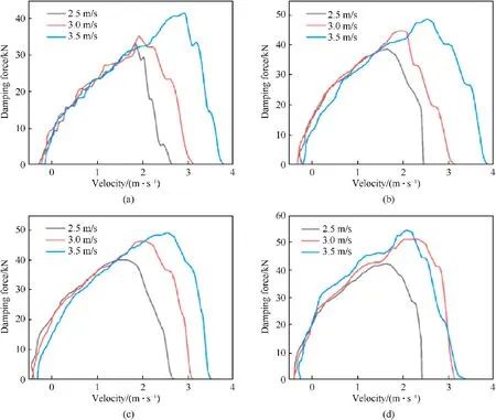
Fig.10.Damping force-velocity curve under three impact working conditions: (a) ρ = 1.5 g/cm3; (b) ρ = 1.75 g/cm3; (c) ρ = 2.00 g/cm3; (c) ρ = 2.25 g/cm3.
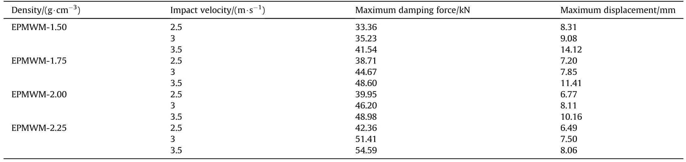
Table 8Results under different EPMWM densities.
5.2.2.Effectofviscousfluidwithviscosityontheperformanceofthe compositebuffer
The characteristics of viscous fluid inevitably affect the buffer performance of the composite buffer.To analyze the influence of the fluid viscosity of viscous fluid on the performance of the composite buffer, two kinds of dimethyl silicone oil with viscosity of 1 × 10⁵cSt and 5 × 10⁵cSt were selected, the size of damping holes was 6×φ8 mm,the density of EPMWM was 1.5 g/cm3.Figs.11 and 12 respectively show the damping force-displacement curve and damping force-velocity curve with two viscosities under different impact working conditions.
The damping force-displacement curve was approximate to a rectangle,with a relatively gentle buffer stage,which was similar to the ideal energy consumption curve.The damping force quickly reached a larger value, and also quickly fell back.For the damping force-velocity curves under different impact working conditions with the same fluid viscosity, the curve shape kept good consistency.As the impact speed increased from 2.5-3.5 m/s, the maximum damping force and maximum displacement also increased.When the impact hammer contacted the composite buffer, the impact speed and damping force also reached the maximum value.Subsequently, the buffer system tended to be stable,and its speed and damping force gradually dropped to zero.
As shown in Table 9,under the same impact working condition,as the viscosity increased from 1×10⁵-5×10⁵cSt,the maximum damping force increased by 32%-46%, while the maximum displacement decreased by 14%-36%, which indicated that the viscosity had a great influence on the performance of the composite buffer.There were two reasons for this phenomenon: (1) The impact process occurred in a very short time, and the impact movement in the composite buffer was considered as the sudden increase of the flow speed of the viscous fluid.Furthermore, the flow of the viscous fluid between the EPMWM pores was considered as the instantaneous starting flow of the fluid in the slender small hole;(2)The shear flow of viscous fluid was the main factor to produce impact damping force.The damping force depended on the shear stress τ acting in the damping holes and the wetted perimeter χ of EPMWM [45].According to Eq.(25), the dynamic viscositykand shear stress of fluid τ was proportional.Based on the above two points,the damping force generated by the buffer when the viscosity was 5 × 10⁵cSt was greater than the damping force generated by the buffer when the viscosity was 1 × 10⁵cSt.
5.2.3.Effectofdampingholesontheperformanceofthecomposite buffer

Fig.11.Damping force-displacement curve under three impact working conditions: (a) Fluid viscosity = 1 × 10⁵ cSt; (b) Fluid viscosity = 5 × 10⁵ cSt.
Fig.12.Damping force-velocity curve under three impact working conditions: (a) Fluid viscosity = 1 × 10⁵ cSt; (b) Fluid viscosity = 5 × 10⁵ cSt.
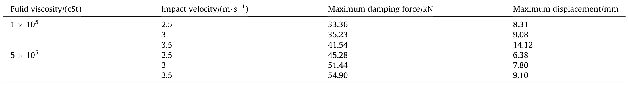
Table 9Results under different fluid viscosities.
In general, the effect of damping holes on the performance of the composite buffer is essentially the effect of the cross section of damping holes.Three specifications of damping holes(6×φ8 mm,4×φ8 mm and 6×φ6 mm)were selected.The corresponding cross section of damping holes were 301.59, 201.06 and 169.65 mm2respectively.The fluid viscosity of dimethyl silicone oil was 1 × 10⁵cSt.The density of EPMWM was 1.5 g/cm3.
Figs.13 and 14 respectively show the damping forcedisplacement curve and damping force-velocity curves with different damping holes under different impact working conditions.In the test of the same damping holes, with the increase of impact velocity, the maximum values of its damping force and displacement gradually increased, and the damping force-velocity curve almost coincided in the later period of buffering, indicating that the buffer performance was stable.
As shown in Table 10, at the same impact velocity, the smaller the cross section of the damping holes, the greater the maximum damping force,and the smaller the maximum displacement.There was an inverse relationship between the cross section of the damping holes and the damping force.The cross section of the damping holes decreased from 301.59-201.06 mm2and 169.65 mm2, respectively, then the maximum damping force increased by 7%-21%and 10%-22%under different impact working conditions, while the maximum displacement decreased by 9%-29% and 6%-23% respectively.
6.Model analysis and parameter identification of the composite buffer under low-speed impact
According to the damping force calculation model of the composite buffer established in Section 4, Eq.(36) is rewritten as the relationship between buffer output forceFand impact velocityV.
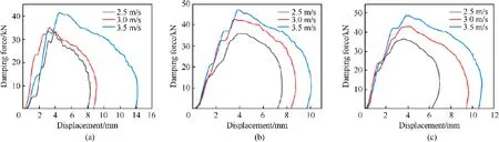
Fig.13.Damping force-displacement curve under three impact working conditions: (a) 6 × φ8 mm; (b) 4 × φ8 mm; (c) 6 × φ6 mm.
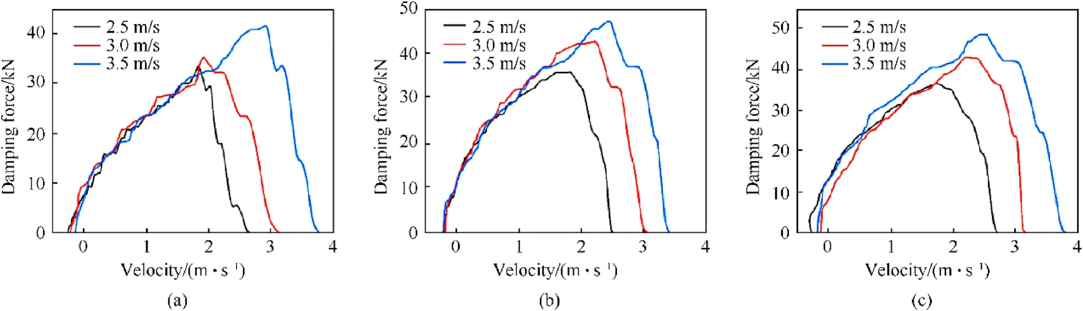
Fig.14.Damping force-velocity curve under three impact working conditions: (a) 6 × φ8 mm; (b) 4 × φ8 mm; (c) 6 × φ6 mm.
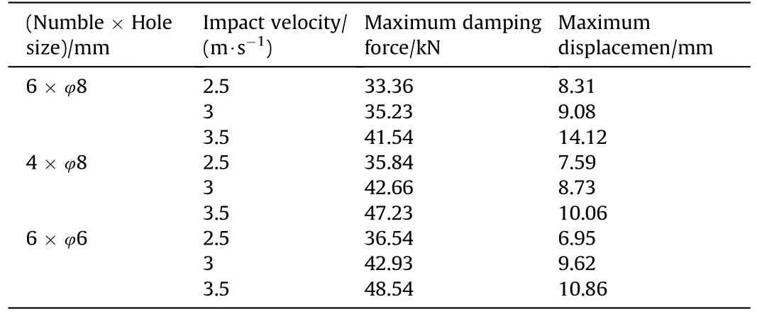
Table 10Results under different damping holes.
whereCis the damping coefficient of the composite buffer,Vis the movement velocity of the piston,α is the speed index of the buffer,which determines the nonlinear size of the buffer.The smaller the speed index is,the greater the nonlinearity of the composite buffer is.
Eq.(38) is taken as the model to be fitted and linearized.
According to the test results in Section 5, the damping forceimpact velocity curve was obtained.The descending section of the damping force-impact velocity curve was selected(the process system is in a stable state).Finally, by fitting the function, lnC,damping coefficientCand speed index α were obtained.The results are shown in Tables 11 and 12.
6.1.Effect of EPMWM density on damping coefficient
Under the same density of EPMWM and different impact velocities, the damping force-velocity curve, fitting curve, damping coefficientC,speed index α and their nonlinear models are shownin Fig.15.The damping coefficient C and speed index α in the corresponding figure under different impact speeds fluctuated with the impact velocity.The average value of fitting parameters under different impact working conditions is shown in Table 11.The speed index α of the buffer was related to the density of EPMWM.When the impact velocity was the same,and the diameter and number of damping holes were the same, the speed indexes of different EPMWM densities were different.The speed index of EPMWM with density of 1.5 g/cm3was greater than that of EPMWM with density of 2.5 g/cm3.Assembling EPMWM with different densities essentially changed the ratio of the effective area A1of the piston to the cross section A2·φ of the flow when the fluid flew through the EPMWM specimen.Therefore, the flow rate of the fluid in the low density was larger.When the buffer structure was determined,the speed index α was inversely proportional to the flow rate, so the speed index α of low-density was low.
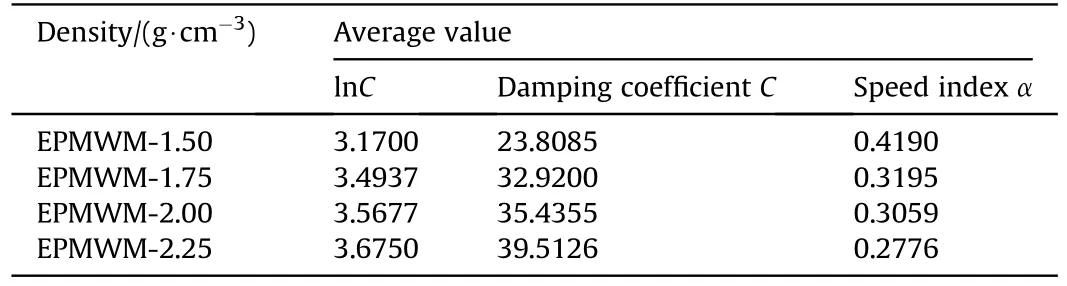
Table 11Damping force model coefficient under different densities.
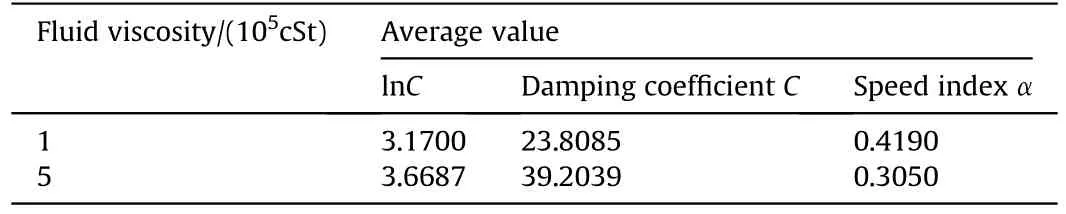
Table 12Damping force model coefficient under different viscosities.
The damping force-velocity curves with different EPMWM densities are shown in Fig.16.With the increase of the density, its damping force gradually increased,which enhanced the nonlinear characteristics of the composite buffer.
6.2.Effect of fluid viscosity on damping coefficient
Under the same viscosity of viscous fluid and different impact velocities,the damping force-velocity curve,fitting curve,damping coefficientC,speed index α and their nonlinear models are shown in Figs.15(a)-15(c) and Fig.17.It can be observed that under different impact working conditions,the damping coefficient C and speed index α in the corresponding figure showed the characteristics of fluctuation, but the overall change amplitude was small.This showed that the flow velocity of viscous fluid in EPMWM was small, and its shear thinning phenomenon was not obvious.The average values of fitting parameters under different impact working conditions are shown in Table 12.Under different viscosity test conditions,the damping coefficient C increased with the increase of viscosity, while the speed index of viscous fluid with viscosity of 5 × 10⁵cSt was less than that of viscous fluid with viscosity of 1×10⁵cSt.This showed that the greater the viscosity of the viscous fluid was, the easier it was to shear thinning, which made the nonlinear characteristics of the damping force generated by the composite buffer more obvious.
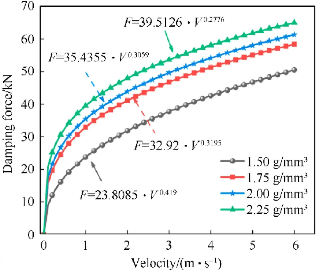
Fig.16.The damping force-velocity curves with different EPMWM densities.
The damping-force velocity curves of with different viscosities are shown in Fig.18.The higher the viscosity of viscous fluid, the more obvious the nonlinear characteristics of the composite buffers.
6.3.Effect of damping holes on damping coefficient
Under the same specification of damping holes and different impact velocities, the damping force-velocity curve, fitting curve,damping coefficientC, speed index α and their nonlinear models are shown in Figs.15(a)-15(c) and Fig.19.It can be seen that the damping coefficient C and speed index α in the corresponding figure under different impact working conditions showed a fluctuating upward trend with the increase of impact speed, but the overall change amplitude was small.The average values of fitting parameters under different impact working conditions are shown in Table 13.The speed index of the buffer was related to the cross section of the damping holes.The damping coefficient C of different damping hole specifications increased with the decrease of its cross section, while the velocity index α decreased with the decrease of its cross section.
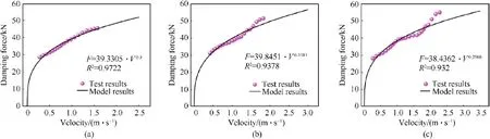
Fig.17.Damping force-velocity curve and its fitting curve of the composite buffer: fluid viscosity = 5 × 10⁵ cSt, (a) condition 1, (b) condition 2, (c) condition 3.
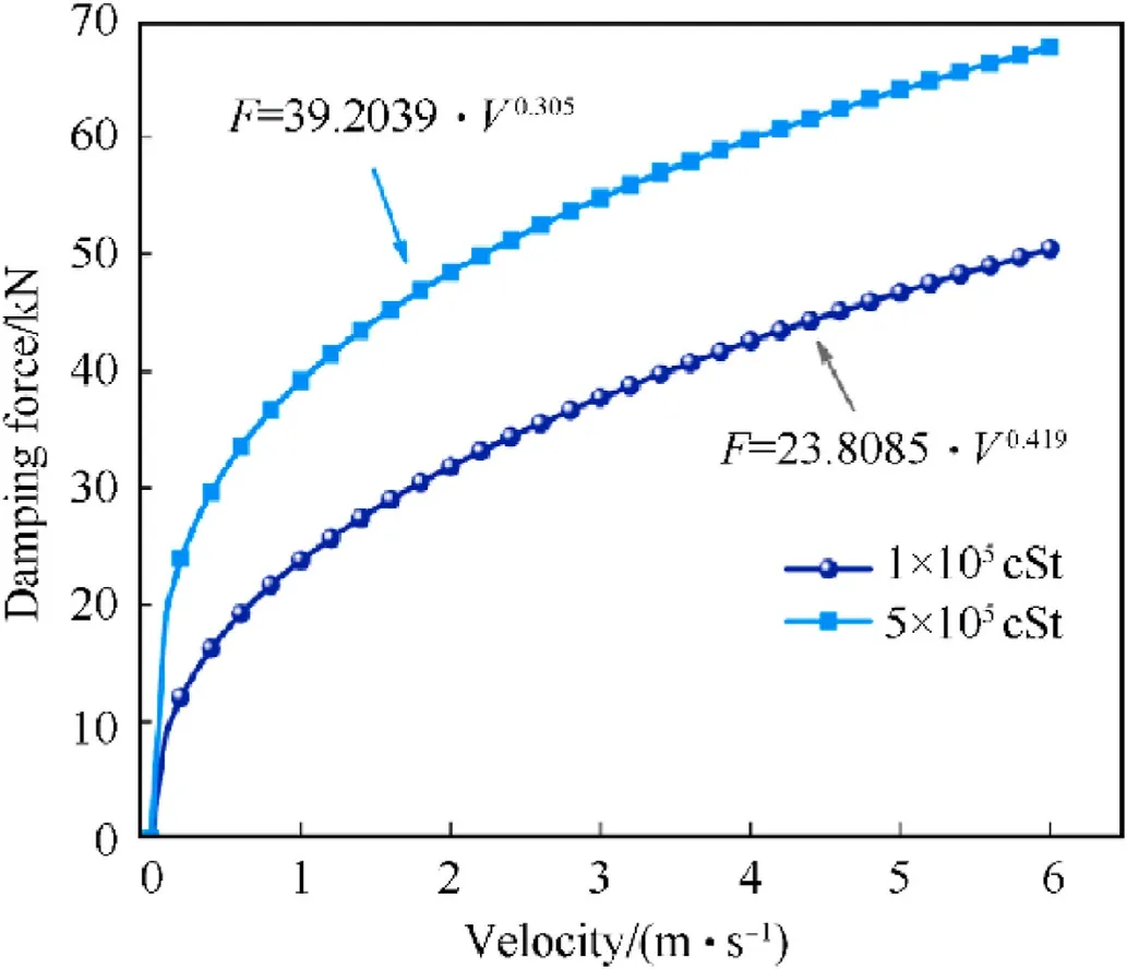
Fig.18.The damping force-velocity curves with different fluid viscosities.
The damping force-velocity curves of the composite buffers with different damping hole specifications are shown in Fig.20.The damping force of the composite buffer increased with the decrease of the cross section of the damping holes, and its nonlinear characteristics were more significant.
7.Conclusions
In this paper, a concept of porous medium and fluid coupling buffer is proposed,and the composite buffer filled with EPMWM in the piston as a porous throttling element was designed for impact prevention of the weapon equipment (such as artillery, mortar,etc.).Through the drop hammer impact test system,the composite buffer with EPMWM and viscous fluid were studied theoretically and experimentally, and the following conclusions are obtained:

Fig.19.Damping force-velocity curve and its fitting curve of the composite buffer: 4 × φ8 mm, (a) condition 1, (b) condition 2, (c) condition 3; 6 × φ6 mm, (d) condition 1, (e)condition 2, (f) condition 3.

Table 13Damping force model coefficient under different damping holes.
(1) The porosity, hydraulic diameter and maximum pore diameter of EPMWM were theoretically deduced and calculated.According to the mercury intrusion method, the pore distribution characteristics of EPMWM were measured.The test results showed that the error between the measured value and the theoretical value was within 5%, which further verified the accuracy of the theoretical calculation equation.
(2) In the low-speed impact test, the maximum damping force and maximum displacement of the buffer increased with the increase of impact velocity.The maximum damping force increased with the increase of the density of EPMWM, and the increase of the viscosity of the viscous fluid, and the decrease of the cross section of the damping holes,while the maximum displacement was on the contrary.The damping force-velocity curves under different impact working conditions almost coincided in the smooth buffer stage, indicating that the buffer performance was stable.
(3) According to the fluid flow continuity equation, the calculation model of the damping force of the composite buffer was deduced and established.Based on this model,the damping force-velocity curve under low-speed impact was identified.The damping coefficient increased with the increase of the density of EPMWM and the viscosity of the viscous fluid,and increased with the decrease of the cross section of the damping holes.Its nonlinear characteristics were more significant.Through parameter identification, the nonlinear models of damping force of different buffers were obtained,which had guiding significance for the practical application of the composite buffer type.
Because the pores in EPMWM will change when the specimen is compressed and deformed during the impact process.How to explore the adaptive adjustability of the changing internal damping hole characteristics and the impact process is the direction that we need to further explore in the future work.
Data availability
The data used to support the findings of this study are available from the corresponding author upon request.
Declaration of competing interest
The authors declare that they have no known competing financial interests or personal relationships that could have appeared to influence the work reported in this paper.
Acknowledgements
This work was supported by the National Natural Science Foundation of China (Grant No.51805086).
- Defence Technology的其它文章
- The interaction between a shaped charge jet and a single moving plate
- Machine learning for predicting the outcome of terminal ballistics events
- Fabrication and characterization of multi-scale coated boron powders with improved combustion performance: A brief review
- Experimental research on the launching system of auxiliary charge with filter cartridge structure
- Dependence of impact regime boundaries on the initial temperatures of projectiles and targets
- Experimental and numerical study of hypervelocity impact damage on composite overwrapped pressure vessels