
Revolutionary entrapment model of uniformly distributed swarm robots in morphogenetic formation
2024-02-29 08:23ChenWngZhohuiShiMinqingGuWeichengLuoXiominZhuZhunFn
Defence Technology 2024年1期
Chen Wng , Zhohui Shi , Minqing Gu , Weicheng Luo , Xiomin Zhu ,Zhun Fn ,c,*
a Shantou University, Shantou, Guangdong, China
b National University of Defense Technology, Changsha, China
c Key Lab of Digital Signal and Image Processing of Guangdong Province, China
Keywords: Swarm intelligence Revolutionary entrapment Flocking Robots Gene regulatory network Vicsek-model Entrapping multiple targets
ABSTRACT This study proposes a method for uniformly revolving swarm robots to entrap multiple targets,which is based on a gene regulatory network, an adaptive decision mechanism, and an improved Vicsek-model.Using the gene regulatory network method, the robots can generate entrapping patterns according to the environmental input, including the positions of the targets and obstacles.Next,an adaptive decision mechanism is proposed, allowing each robot to choose the most well-adapted capture point on the pattern, based on its environment.The robots employ an improved Vicsek-model to maneuver to the planned capture point smoothly,without colliding with other robots or obstacles.The proposed decision mechanism, combined with the improved Vicsek-model, can form a uniform entrapment shape and create a revolving effect around targets while entrapping them.This study also enables swarm robots,with an adaptive pattern formation, to entrap multiple targets in complex environments.Swarm robots can be deployed in the military field of unmanned aerial vehicles’ (UAVs) entrapping multiple targets.Simulation experiments demonstrate the feasibility and superiority of the proposed gene regulatory network method.
1.Introduction
The development of swarm robot system is a challenging endeavor in robotics [1].Swarm intelligence is based on the concept that individuals,through cooperative interaction,produce collective intelligent behaviors [2,3].Extensive research on swarm robotics has been conducted in recent years [4-9].Swarm intelligence has various applications,including industrial manufacturing[10], warehouse logistics [11], disaster response [12], scenario reconstruction [13], and military surveillance [14].
Entrapment is one of the main directions of swarm intelligence research.Entrapment methods are primarily classified as follows:behavior-based approach [15,16], leader-follower model [17,18],virtual structure method [19,20], and biomimetic approach[21-25].The key idea of the behavior-based approach is the design of various basic behaviors and an effective behavior coordination mechanism.Basic behaviors include robot collision avoidance,obstacle avoidance, and formation maintenance [15,16].This method is suitable mostly for simple tasks.For the leader-follower method,an agent in the system is designated as the leader,and its trajectory is controlled [17,18].The individual agents follow the leader.Meanwhile, the following agents maintain a specific geometric relationship with the ones leading.However, this method cannot enable the agents to generate an adaptive formation suited to the environment according to the environmental information.The virtual structure method considers the system to be a rigid body virtual structure,and each member controls its own behavior according to its position relative to that structure.The process of this method is as follows:(1)The desired dynamic behavior of the virtual structure is specified;(2)The motion of the virtual structure is translated into the desired motion of each robot; and (3) each robot assumes the expected behavior [19,20].However, when agents are in a complex environment with obstacles,a fixed shape cannot cope with the environment flexibly.Wang et al.proposed an adaptive algorithm named AGENT for entrapping multiple targets based on Vicsek-model[21].This method enables swarm robots to avoid obstacles flexibly, and uses adaptive group division for entrapping multiple targets.
Another interesting line is the method based on biological inspiration.The gene regulatory network (GRN) is a robust selforganizing mechanism for simulating biological morphogenetic development.Recently, the GRN method has been used in multirobot entrapping tasks [22-25].Jin et al.[26] proposed a hierarchical GRN (H-GRN) that enabled the agents to generate an entrapping formation according to the environmental changes.Oh et al.[27,28] proposed an evolving hierarchical GRN (EH-GRN) for swarm robots to entrap targets in environment with obstacles.Peng et al.[29] proposed a pattern adaptation strategy where robots entrapped each target separately with split sub-patterns.Wu et al.[30] introduced a cooperation-based GRN method assuming that the agent can use sensors to receive information about its neighbors and record it in its own coordinate system.The partner's position was used as input to trigger changes in pattern formation.Building on GRN-based research, Fan et al.[31] proposed an automated design framework, including structures and parameters,with the genetic programming method for automatically generating entrapment patterns.The framework generated GRN models exhibiting better performance compared with those designed by human experts in complex and dynamic environments yet with simpler GRN structures.
Although the previous GRN method provides an effective pattern generation mechanism for robot swarm entrapment,it still has some areas to improve.For example,it lacks an efficient swarm decision-making mechanism that can realize a uniform pattern distribution of robots for entrapping multiple targets.In addition,the robot while entrapping targets may repeatedly jump forward near the generated pattern and have a non-uniform position distribution relative to the pattern,which desires for a better velocity control mechanism.In this paper, we propose a multiple-target uniformly revolving entrapment GRN (RE-GRN) algorithm with a decision-making mechanism and velocity control mechanism to solve these two problems.
The primary contributions of the study are as follows:
·The structure of the RE-GRN method is divided into three layers: Entrapment pattern generation layer, decision-making layer, and motion control layer.This framework can be used to extend the execution of various swarm tasks by modifying the relevant layer.
· A new mechanism to allocate captures points to entrapping patterns is proposed.The number of capture points corresponds to the number of robots and targets.This approach improves the uniformity of the division of robot groups when entrapping multiple targets.
·A decision-making mechanism for each robot in the swarm is proposed that allows it to choose the most suitable capture point in the pattern that revolves about the pattern as the target moves,facilitating more efficient and effective entrapment.
·An improved Vicsek-model to achieve smooth motion of the robots towards their target points mimicking natural population motion is proposed.With this method,the robot can adaptively and smoothly travel through complex obstacles to reach the target point according to the environmental conditions.
To the best of our knowledge, this is the first study where the agents can revolve around targets along the changing entrapping pattern and entrap the targets.It can make the robot maintain a relatively higher entrapping velocity and constantly change the entrapping position, so that the target cannot obtain a static entrapping formation gap,which prevents the target from escaping through the gap of the entrapping formation and enable the robot swarm to achieve tighter and more flexible entrapment [33-35].Furthermore, if the swarm robots keep relatively static with the target, they will not have the speed advantage when the target wants to escape.In this case, the speed of the swarm robots revolving around the target will enable them to respond more quickly when the target attempts to escape, which reduces the requirements for the robot to accelerate to a certain speed.Moreover, orbiting the target enables the sensors carried by the swarm robots, such as visual sensors, play a greater role.If other targets appear,they are more easily detected by the patrolling robots,and the formation can be adjusted more responsively when robots have a certain starting speed.In conclusion, the entrapping mechanism proposed in this study is beneficial and worth to be further investigated.
The rest of the paper is organized as follows.Section 2 presents the research question and summarizes the methodology.Section 3 proposes the methods,including the difference equation of the REGRN model suitable for robotics to generate entrapping morphologies, the selection criterion of the robot's target points on the entrapment pattern to achieve a uniform distribution, and the maneuvering of the robots to the target point.Section 4 compares the RE-GRN method with the previous GRN as well as AGENT methods, with comprehensive experimental results analyzed.Section 5 summarizes the study's findings, limitations, and future research directions.
2.Problem statement
Gene regulation is the mechanism by which organisms control gene expression.The GRN method is mainly divided into three aspects.First, regulation at the DNA level, transcriptional control,and translational control.Second,microbes adapt their metabolism to the environment through the GRN.Third, multicellular organisms enable cell differentiation, morphogenesis, and ontogeny through biological gene regulation.This study mainly draws on the mechanism by which microorganisms adapt to their environment by changing their metabolism through gene regulation.Microorganisms exhibit a high degree of adaptability to environmental conditions during development and rapidly regulate the expression levels of various genes in response to environmental stimuli.
Previous studies [21-28] utilized GRNs and morphological gradients to realize the morphogenesis of swarm robotic systems.The fundamental idea of applying gene expression mechanisms in biological morphogenesis to swarm robotic control is to establish an analogy between microbes and robots.Microorganisms regulate their own protein production based on environmental information.Changes in protein concentration affect the environmental information received by microorganisms,affecting the microorganisms in return.Microorganisms undergo this regulatory process to better adapt to the environment.The behavior pattern of this type of microorganism is analogous to that of a robot.A robot also establishes the concentration field of the target and obstacles information and adjusts its movement through its own concentration field accordingly, which, to a certain extent, reflects the environmental adaptability of the robot.
In this study,the GRN was used to coordinate a swarm of robots to entrap multiple targets.As illustrated in Fig.1,the algorithm has a three-layer structure: An upper layer, a transition layer, and a lower layer.The robot maps the target and obstacle position information in the upper layer to generate the intermediate productsg1,g2,g3and .These products represent concentration maps with different levels of information about the target and the obstacles(e.g.,g1is the robot considering the concentration information required to fly close to the target,g2is the concentration information for the robot to fly away from the obstacle,g3simultaneously couples the concentration information of the robot flying away from the obstacle and close to the target).The robot generates a concentration information map that adapts to the current environment by regulatingg1,g2,andg3.The mechanisms ofg1,g2,andg3(including the logical structure and parameters)is automatically evolved by genetic programming.The robot samples the concentration field with a specific concentration value to take the target surrounding form M which considers both the obstacle and target information in the robot's environment.
The second layer is the transition layer.Based on the two-layer structure of the original GRN, we constructed the transition layer for the robot's decision-making mechanism.After that, the robots select the most suitable capture points, which are uniformly distributed along the entrapping pattern.In addition,the robot can revolve along the entrapping pattern, creating a flow entrapping effect like the fluidity of cell membranes (the cell membrane also flows to wrap the cell).In this layer, each robot selects its most suitable capture point in real time.In Fig.1,the robot's decision for the capture point is denoted by D.
The third layer of RE-GRN provides a new velocity control mechanism, in which the robot navigates towards the target position through a modified Vicsek-model (represented by F in Fig.1).Gabor et al.[32]presented a flocking velocity control model based on the Vicsek-model for real drones.Their experiments demonstrated that the induced swarm behavior remained stable under realistic conditions for large flock sizes.Inspired by this research,we propose an improved Vicsek-model, which considers four velocity action terms:the movement of the robot to the goal capture points (represented by t), obstacle avoidance (represented by o)and collision avoidance between robots and targets(represented by r).Finally, the vector superposition of the separately calculated velocity components determines the predicted speed of the robot at the time.The maximum limit was superimposed on this velocity for practical considerations of engineering applications.In this way,the robot can achieve a smooth maneuver to its goal capture point,leading to a collective movement behavior of the robot swarm similar to that of a natural population.To the movement pattern of the natural population.
Based on the three-layer mechanism, robots can uniformly entrap multiple targets, revolving in each pattern and tightly entrapping each target.Throughout the movement process, the robot swarm maneuvers as smoothly and naturally as the natural population.The design flowchart of the RE-GRN method is illustrated below.
3.Methods and strategy
3.1.Upper layer: gene regulatory networks generate entrapping morphologies
In the upper layer of the RE-GRN, robots generate the morphologies(patterns)for entrapping multiple targets.These patterns can be automatically generated by conceptualizing automation ideas.The automated design of a GRN can significantly reduce the workload on human designers.In another study [31], we used genetic programming to automatically assemble and optimize the GRN superstructure and parameters.A fitness function and a series of assembly rules were established to generate the optimal structure adapted to the environment.For further details on the design of the upper layer of the RE-GRN method, readers are referred to Fan et al.[31].
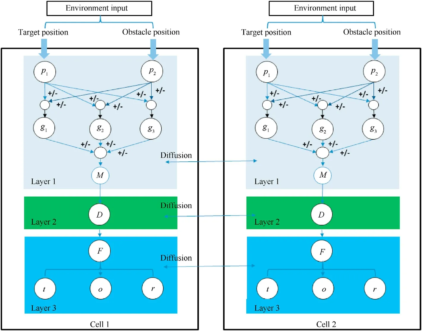
Fig.1.Flowchart of the multiple-target uniformly revolving entrapment (RE-GRN) algorithm.
After constructing the upper layer of the GRN by genetic programming,we derived the differential equation for the generation mechanism of the concentration of the upper layer of the network.The commonly used mathematical models of the GRN include the directed graph, Boolean network, Bayesian network, differential equation, and difference equation model.Differential equation models are widely used to construct small and precise GRNs.The upper-level mechanism of the RE-GRN converts the differential equation form of the original GRN into a difference equation one.We assume that the robots can detect the locations of the targets,obstacles, and other robots in the environment during the entrapment task.The robots can communicate with one another to share information about the positions of the targets and obstacles.During the pattern-generation process, as the absolute position information of the target is the same for all robots, they establish the same pattern when applying the same RE-GRN mechanism.Specifically, the upper layer equation of the RE-GRN is as follows:
The computation of the concentration gradients of the target and obstacle by the Laplacian operator can be considered as a simulation of the concentration diffusion of proteins in a biological system.By solving the above equation, we obtained the form ofpj(t) as follows:
where,x(t) andy(t) are the horizontal and vertical coordinate distances of the robot from a target or obstacle.As this distance may vary with time, it can be expressed as a function of timet.The exponentvis the concentration diffusion factor,which can be used to adjust the mapping relationship between distance and concentration.pj(t)represents the protein concentration generated by thejth target or obstacle location information.p represents the comprehensive protein concentration produced by all the detected targets or obstacles at the current robot position fromj=1 toNt.Among them,Ntis the total number of detected targets or obstacles.
The robots construct the concentration information fieldsg1,g2,andg3on the map after processing the obstacle or target position information.The upper layer of the RE-GRN can take several forms.Therefore,the methods of calculatingg1,g2,andg3in the upper layer of different GRNs are not identical.Particularly,in the superstructure of the RE-GRN,g1andg2process the inputs of the target and obstacle position information separately.The final concentration information field is then coupled byg3to form the information map with the highest concentration of robots.ris the distance between the robot and the target(or the obstacle).We assume that β1,β2,and β3are the thresholds of the sigmoid function.Thus, by adjusting β, we can adjust the interval range of the entire generated concentration field.iis the concentration difference adjustment coefficient.The larger thek,the more evident the concentration difference.A smallerkmakes the concentration difference close to linear.The range ofkis the concentration difference adjustment coefficient.The larger thek,the more evident the concentration difference.A smallerkmakes the concentration difference close to linear.The range of β is 0-1, and the range ofkis 0- 2
Through this mechanism, the concentration fields of the obstacle and target position information are calculated using Eq.(3)and Eq.(4), respectively.The processed fields are combined into a concentration field(Fig.2)by using Eq.(5)-Eq.(8)containing both types of information.
The robots sample the specific concentration values on the final concentration map to form a pattern suitable for the current situation.If the robots assemble into this pattern,they can surround the targets while avoiding the obstacles.Thus, the swarm robots only need to aggregate in this pattern and produce the desired swarm behavior.
3.2.Transition layer of RE-GRN: decision making
In Subsection 3.1, the RE-GRN algorithm provides an entrapment pattern that adapts to the environment of the robots.In this section, we attempt to design a reasonable mechanism that can make robots allocated for the capture points on the pattern, to satisfy the condition of the uniform distribution of the swarm robots on the pattern generated by the upper layer of the RE-GRN.To this end, we construct a mechanism to allocate capture points to the swarm robots.The algorithm for this mechanism is as follows:
Algorithm 1.An adaptive uniform allocation framework for the capture points on multiple-target entrapment pattern
Input:Location of the pattern, number of robots, positions of robots;
Output:The capture points on the pattern of robot i.
1.The number of robots is defined asNr.The number of patterns isNp(patterns will merge if targets are too close;hence, the number of robots should be evenly distributed according to the number of patterns).
2.Calculate the sampling interval for the capture points in the current situation.m=Nr/Np.
3.The capture points are numbered 1 tomcounterclockwise from the reference point.When the robot is not assigned to a capture point, its flag is 0.If not, it stores the capture point number and changes its flag to the capture point number.
4.If robotihas the highest priority in the swarm,robotiselects capture points as reference points and broadcast to the swarm.Or robotireceives the reference points through communication.

Fig.2.Concentration field formed by considering the concentration information of both targets and obstacles.
5.Robotisamples each pattern intoNpoints withN/mas the sampling interval,and obtainmpoints as the capture points of the robots.Nis a self-designed integer multiple ofm.
6.The robotitraverses all capture points in its list and finds the nearest one.The robot broadcast its own flag and the distance to its capture point.
7.forj= 1 toNr
8.IfRobot i’s flag is same with robotj’s falg (that is, the two robots have selected same capture point;here,it is assumed to be capture pointe.The distance between the robotiand the capture point e <the distance from the robotjto the capture pointe.then
9.Establish the mapping relationship between the robotiand the capture pointe.
10.else
11.Establish the mapping relationship between the robotjand the capture pointe.The robotiremoves the capture pointefrom its list.Go to 6
12.end if
13.end for
14.The robotiuses the Vicsek-model to approach its capture point.
To ensure that all robots in the distributed system obtain the same information about the capture points, the robots need to determine the reference point(the first capture point)of all capture points through communication.The robot with the highest priority in the swarm(preset by the system)determines the reference point by random in the pattern and constantly broadcasts the position of the reference point to the other swarm robots.If the robot with the highest priority in the system is damaged, the robot with the second highest priority will assume its role again and so on.All robots in the swarm will receive the position information of reference point.Meanwhile the pattern is divided into segments to obtain the list of capture points.In the capture point allocation mechanism,the list of capture points calculated by all robots is the same.Every robot autonomously selects the capture point most suited(considering the distance factor and the other robots’ position) to their current position.Consequently, the robots achieve a reasonable distribution of capture points on the pattern and choose the most suitable capture point as the destination.
As mentioned earlier, the robot's revolution around the target reduces the chance that the target accelerates away if the target does not want to collide with the robot.We propose a mechanism to help the robots revolve in the entrapment pattern, called reference point change.Here,the change of the reference point(the first capture point)forces all capture points to change,thus leading the robots to revolve in the pattern.In order to express this mechanism more clearly, we model the circular pattern in the ideal environment.The pattern will change its position with the movement of targets.After the robot has confirmed the reference point and used it to determine all capture points, the reference pointe1on the pattern will change to the closest capture pointe2in the pattern at the next moment, which becomes the new reference point (The overall position of the pattern will change as the target moves,and accordingly the positions of all the capture points on the pattern),and the process is repeated.Fig.3 depicts a standard circular pattern as an example (the entrapment pattern in a free obstacle environment with one target is a standard circle) to model the revolution mechanism.Thus, the robots exhibit revolutionary motion.The figure has two straight lines: the connecting line between the positions of the reference point and the target, and the straight line with the target's direction of motion.We define the angle between these two straight lines as θ(t).The angle between two lines at the next moment is θ(t+ 1).
However, under this behavioral mechanism, the revolution behavior of the robot is not constant.In the case of constant target motion,if the reference point moves to the intersection(s1)of the reverse extension line of the target's motion direction and the pattern,the reference points1 is closest to the reference points2 in the new pattern and the direction of movement of the robot froms1 tos2 is parallel to the direction of target motion.At this time, the robot stops revolving in the pattern, while the target continues to travel in the same direction.To sustain this revolution behavior,robots limit the change of the reference point position to one cycle(c1-c2).For representation, as illustrated in Fig.4, the target is placed at the center of the circle, the direction of velocity of the target is the 0°reference axis, and the reference point is (counterclockwise) betweenwithin the angular range.Here,Npis the number of patterns,andNris the number of robots.Initially,the robot in swarm with highest priority randomly selected a capture point as the reference point.As this reference point moves with the target toc2 (revolvingcounterclockwise from the 0°reference axis),the reference point is reset to the capture point nearc1 (revolvingcounterclockwise from the 0°reference axis).This process is repeated continuously to realize the periodic transformation of the reference point.The following equation calculates the revolutionary velocity of the robot as a function of time, as the robot encounters a circular pattern.
where,vr(t+1)and θ(t+1)are the magnitude and direction of the revolutionary velocity of the robot in the pattern, respectively.Notably,the equation is fully applicable when θ is an acute angle.At timet+1,the revolutionary velocity component of the robot along the pattern is deduced as follows.For an obtuse included angle,the target is assumed to have reversed its direction.Thus,it becomes an acute angle according to the definition of θ, and the equations are still applicable.Particularly,its velocity when θ is a right angle is as follows.
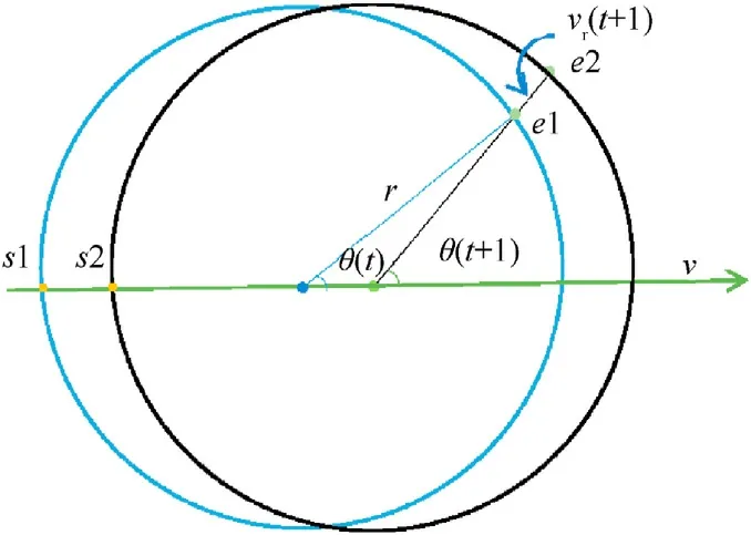
Fig.3.Schematic of the scenario of a robot switching capture points in a standard circular pattern.

Fig.4.Schematic of the scenario of a robot switching the reference point in a standard circular pattern.
3.3.Lower layer of RE-GRN: motion control
The first two layers(upper and transition layers)of the RE-GRN were introduced in the last two sections.In the upper layer, the robots generate the concentration field, while in the transition layer, they sample the field to generate a pattern and adaptively allocate capture points to uniformly entrap multiple targets.Each robot must move to the corresponding position on the target's entrapping pattern.To this end, we proposed a flocking motion velocity controller based on an improved Vicsek-model.Although the upper layer of the RE-GRN already considers the position information of obstacles and targets,the robots may still be relatively too close to the obstacles or targets as they form the pattern.Therefore,the purpose of the lower layer algorithm is to allow the robots to smoothly navigate to the capture points calculated in the first two layers of the RE-GRN without colliding with the neighboring robots, targets, or obstacles.Therefore, this section is divided into three parts, including repulsion, obstacle avoidance,and maneuvering toward the target.
3.3.1.Repulsion
As the robot maneuvers, it may occasionally tread too close to other robots.For safe navigation, we introduced a mutually exclusive speed between robots in the Vicsek-model [32].rarepis the distance at which the local repulsion is activated,and larger values create sparser flocks with fewer collisions.If the distance between the agents is less than rarep, the robots will generate a repulsion velocity to maintain a safe distance from their neighbors.
where,rij=is the distance between robotiand robotjrepresents the direction(unit direction vector)of velocity of robotjtoward roboti.is the linear coefficient of the repulsion velocity between robots.The robots may also maneuver too close to the target as they approach the capture point.To prevent the robots from colliding with the target,we set a unidirectional repulsion velocity between the robot and the target (in the swarm robot system, the target is considered to be unaffected by the robot).If the distance between a robot and its target is less thanrtrep, the robot will generate a velocity away from the target.
They knocked at the door, and when the woman opened it she exclaimed: You naughty children,25 what a time you ve slept in the wood! we thought you were never going to come back
Similarly,rit=|ri-rt| is the distance between robotiand its targets.rit=represents the direction(unit direction vector)of repulsion velocity of the target toward roboti,is the linear coefficient of the repulsion velocity between a robot and its targets.The algorithm in each robot should calculate the repulsion velocity term for all the targets.
In order to get all the repulsive forces on the roboti, we calculated the vectorial sum of the interaction terms of repulsion:
3.3.2.Obstacleavoidance
A robot may encounter obstacles as it approaches the capture points on the pattern.To allow the robot to maneuver smoothly as it circumvents an obstacle,the obstacle avoidance speed should be gradually attenuated at a greater distance from the obstacle.FunctionD(r,a,p)can provide a smooth velocity decay curve for the velocity change between the robot and the desired stopping point,whereris the distance between the robot and the desired stopping point,pdetermines the crossover point between the two phases of deceleration, andais the robot's preferred acceleration [32].
To help the robot safely avoid collision with an obstacle in the environment, we assume the presence of a virtual agent at the point closest to the robot on the boundary of the obstacle[36].Each robot has a corresponding virtual agent as it approaches an obstacle, and the position of the virtual agent changes with the position of the robot.
where,cdis the strength(velocity coefficient)of the distance from the obstacles, androbsis the safe distance between the robot and the obstacle.Larger values of this distance prompt the robot to start braking at greater distances from the obstacle.rid=|ri-rd| is the actual distance of the robotifrom its nearest obstacle.vid= |vivd|, where vdis the velocity of the virtual agent pointing perpendicularly inward to the boundary of the obstacle in the arena.vid=,vidis the unit direction vector of the velocity vector difference between the robotiand its virtual agent.This obstacle avoidance method helps the robot avoid falling into the local minimum.adis the maximum allowed acceleration on the optimal braking curve.Higher values of this acceleration imply faster braking by the robot.Excessively high values would result in the failure of the robot to react to excessively large velocity gradients in time, thus causing collisions.pdis the linear gain of the optimal braking curve,which is used to determine the maximum allowable velocity difference.Large values of this gain approximate the braking curve to the constant acceleration curve, while small values elongate the final part of the braking (at a small velocity) with decreasing acceleration and smoother stops.
3.3.3.Movetowardthegoalposition
Another topic of interest is enabling the robot to approach the goal capture point with a gentle velocity.As introduced earlier,the functionadestablishes a mapping relationship between the velocity and the distance to the desired goal capture point,forming a smooth velocity decay curve affected by the distance factor.In this section, we employ the following function to construct a new navigation speed function for the goal capture point.
where, the initial velocity vfof the agent is preset, andCgis the preferred common traveling velocity coefficient for all agents to approach the goal position.is the distance between the agentsagand its goal position.agis the maximum allowable acceleration on the optimal braking curve.pgis the linear gain of the optimal braking curve, which is used to determine the maximum allowable velocity difference.agandpgare the same asadandpd,but for wall alignment interactions.rgi=,rgiis the direction(unit direction vector) in which the agent points toward the goal position.It is worth noting thatritandrigare different.ritis the distance from the robotito the target, andrigis the distance from the robotito the position of the goal entrapping point on the entrapping pattern.
3.3.4.Finalequationofdesiredspeed
The robot needs to consider both these velocity effects.We calculate the vectorial sum of all the interaction terms:
For practical applications, we set a cutoff velocity vlimitto compensate for the motion restraint.If the velocityexceeds the limit, then maintaining the direction of the desired velocity while reducing its magnitude yields the following equation:
4.Experiments and index evaluation
4.1.Simulation experiments
In this section, the performance of the proposed RE-GRN method is verified using simulation experiments based on MATLAB and CoppeliaSim simulation platform.Simulations based on MATLAB are used for proof-of-concept given global information.We used GRN method, AGENT method and RE-GRN method to do the comparative experiment in five scenarios to verify the validity and robustness of these methods.In the RE-GRN simulations based on MATLAB,the robots obtain the same obstacle and target position information in the same coordinate system (with global information known), so the entrapping shape calculated by them is identical.The robots can communicate with each other to determine the location of the reference point to synchronize the locations of all the capture points.The following five scenarios are considered.
(1) Obstacle-free environment.Two targets are in circular motion around a fixed point in the arena and are being trapped by agents (Scenario 1).
(2) Fifteen robots trap two targets.The environment contains two obstacles (Scenario 2).
(3) Ten robots trap one target.The unknown environment contains several obstacles.The robot may encounter an unforeseen obstacle around the next corner (Scenario 3).
(4) Fourteen robots trap two targets.The environment has many barbed obstacles (Scenario 4).
(5) Twelve robots trap two targets.The environment has several square obstacles in the environment.Two targets move arbitrarily in the environment (Scenario 5).
As demonstrated by these scenarios (Figs.5-17), the RE-GRN performs best among the three methods can realizing that the robot swarm orbits the target while entrapping the target.The previous GRN method has an evident problem of the irregular distribution of robots in a pattern.The robots jump back and forth into the pattern when approaching it but do not completely settle down on it.The RE-GRN method overcomes this drawback.The robot applying AGENT method achieves a better entrapping effect than the GRN method, but the entrapping effect is not as ideal as the RE-GRN method, which is reflected in the fact that AGENT method cannot enable a revolving entrapping effect, and the uniformity of entrapping is not as good when trapping multiple targets.
Notably,the method demonstrates distinct advantages over the existing method when entrapping multiple targets with swarms.As observed in Fig.15-Fig.17,the two targets perform a L'evy flight[37] above the field (a random movement step generation mechanism when some living creatures forage),and the robots apply the GRN method, AGENT method and RE-GRN method to respectively entrap the two targets.The division of groups in the RE-GRN method is evidently more uniform than that in the GRN method and AGENT method when trapping multiple wandering targets.In the RE-GRN method, the robots are uniformly distributed on the pattern,and constantly adjust their motions as the pattern changes.The robots maintain a safe distance from the nearby targets, obstacles, and other robots,avoiding collisions.
To further verify the effectiveness of the RE-GRN algorithm,we conducted more experiments on CoppeliaSim.In this simulation,the location of the target was known.The drones could detect other drones and obstacles within the range of the sensor and broadcast their detected obstacle position information in the swarm.This ensures that all the robots in the swarm eventually have the same concentration map and entrapping pattern.In this way, all robots can synchronize the list of capture points(see Section 3 for specific mechanism).The experimental effect of drones entrapping multiple targets is shown in Fig.18.
Fig.18 shows that, in the case of free movement of multiple targets, the deployment of the RE-GRN algorithm in the drone swarm can deal with multiple targets, achieve adaptive grouping,and uniformly entrap multiple targets.The drone swarm can revolve along the entrapping pattern to tightly encircle the target.The drones’revolving entrapment effect can be observed in the video.
4.2.Index evaluation
By the definition of entrapment, the method must consider distribution of robots in several directions around the target.Therefore,we calculate the occupancy rate of entrapment circle,i.e.the presence of robots in six directions (we divided the 360°area around the target into six sectors) to evaluate the trap quality.Furthermore, the robots must efficiently trap the targets, which may be reflected by the distance the robots traveled to trap those targets.In addition, the robot should also pay attention to its own safety.Therefore,their velocity should not change significantly over time as that could be detrimental to their stability.In summary,this study uses the following evaluation indicators to digitize the experimental results:
(1) The uniformity of the number of robot groups when trapping multiple targets(Fig.19).
(2) The occupancy rate of each target in the entrapment circle(Fig.20).
(3) The average distance traveled by robots to entrap (Encirclement occupancy = 6/6) the targets (Fig.21).
(4) The velocity correlation[32]ψcorrof the robot at consecutive moments (Figs.22-24).
Eq.(20) gives the calculation formula of velocity correlation.
These indicators demonstrate the enhanced performance of the RE-GRN method for multi-target entrapment over the previous method.
As depicted in Fig.19,the robots can be grouped as they entrap multiple targets.The number of robots allocated to each target was calculated and plotted.The data reflect the stability of the RE-GRN method in terms of group division.In Fig.20,the robot forms a tight siege around the target.In most cases, the occupancy rate of the encirclement is 6/6 which confirms the superior entrapping performance of the RE-GRN method.In addition,Fig.21 illustrates the average distance traversed by the robots to trap the targets(Encirclement occupancy=6/6)under the three methods.The REGRN method requires the robots to travel a significantly shorter distance to trap the targets.We have carried out the significance test of difference, and the test results show that the method proposed in this study has significant advantages compared with the two comparison methods.

Fig.5.Twelve robots trap two targets in an obstacle-free environment with the GRN (left), AGENT(middle) and RE-GRN methods (right), and the scenario illustrates their trajectories (Scenario 1).

Fig.6.Fifteen robots trap two targets in the environment of two obstacles with the previous GRN method (Scenario 2).
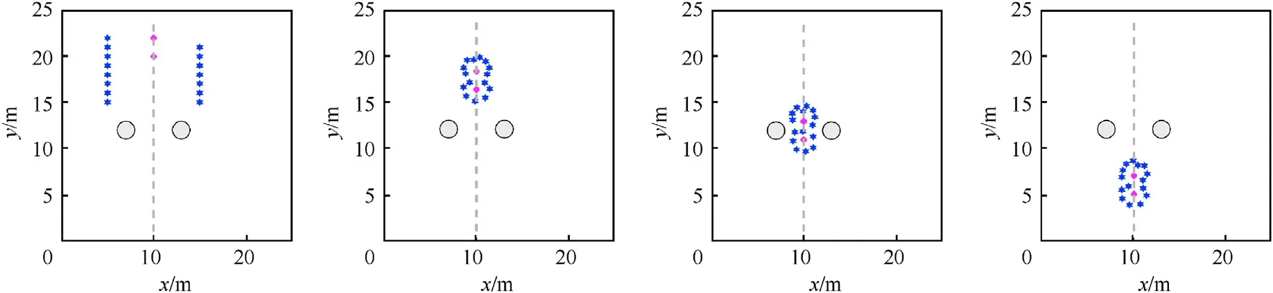
Fig.7.Fifteen robots trap two targets in the environment of two obstacles with the AGENT method (Scenario 2).

Fig.8.Fifteen robots trap two targets in the environment of two obstacles with the RE-GRN method (Scenario 2).
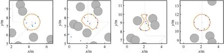
Fig.9.Ten robots trap one target in the environment with many obstacles with the previous GRN method (Scenario 3).
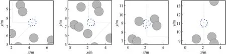
Fig.10.Ten robots trap one target in the environment with many obstacles with the AGENT method (Scenario 3).

Fig.11.Ten robots trap one target in the environment with many obstacles with the RE-GRN method (Scenario 3).
As the robots maneuver, the change in velocity at two consecutive moments must be sufficiently small to meet practical requirements.Figs.22-24 show that in the previous GRN method,the robot's continuous motion correlation is very low, which is close to -1 most of the time, which means that there may be vibration in the robot's motion.In addition,in the AGENT method,the robot's continuous motion correlation is very high,which is close to 1 most of the time,which means that the robot does not change the direction frequently, and does not have the effect of revolution around the target.In the RE-GRN method,the motion correlation of the robot at continuous time is almost evenly distributed between[-1,1],which indicates that the robot changes the motion direction continuously and smoothly in most of the time,reflected by the fact that the robot orbits the target.
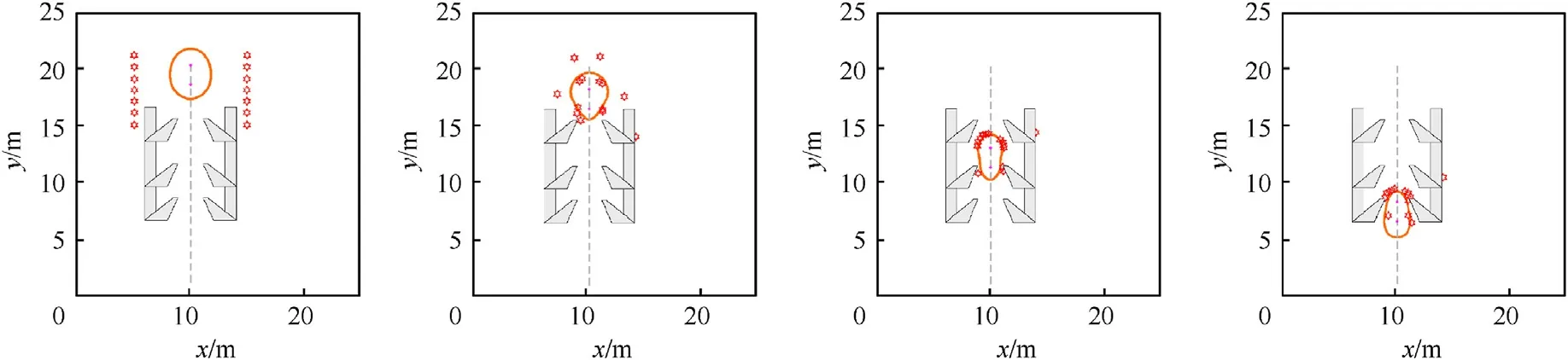
Fig.12.Fourteen robots trap two targets in the environment with barb obstacles with the previous GRN method (Scenario 4).

Fig.13.Fourteen robots trap two targets in the environment with barb obstacles with the AGENT method (Scenario 4).
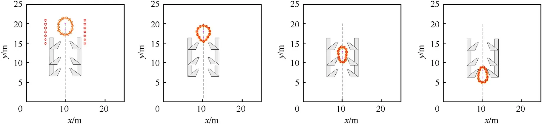
Fig.14.Fourteen robots trap two targets in the environment with barb obstacles with the RE-GRN method (Scenario 4).
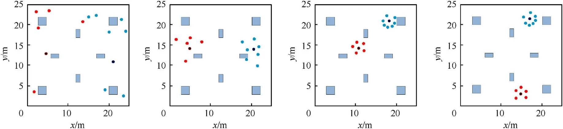
Fig.15.Twelve robots trap two wandering targets in complex obstacle environment with the previous GRN method (Scenario 5).
From the experimental results shown in the video, we can also observe that the robots by applying RE-GRN algorithm can autonomously make decisions when encountering multiple targets and execute the swarm behaviors of grouping while trapping multiple targets.With this method, robots can adapt to the environmental conditions and accordingly change the entrapping pattern without colliding into the neighboring robots or obstacles.The experimental indicators of this study prove the potential of the RE-GRN model in target entrapment applications.The entire system can be deployed on robots in a distributed manner and can be safely applied in industrial and military applications.

Fig.16.Twelve robots trap two wandering targets in complex obstacle environment with the AGENT method (Scenario 5).

Fig.17.Twelve robots trap two wandering targets in complex obstacle environment with the RE-GRN method (Scenario 5).
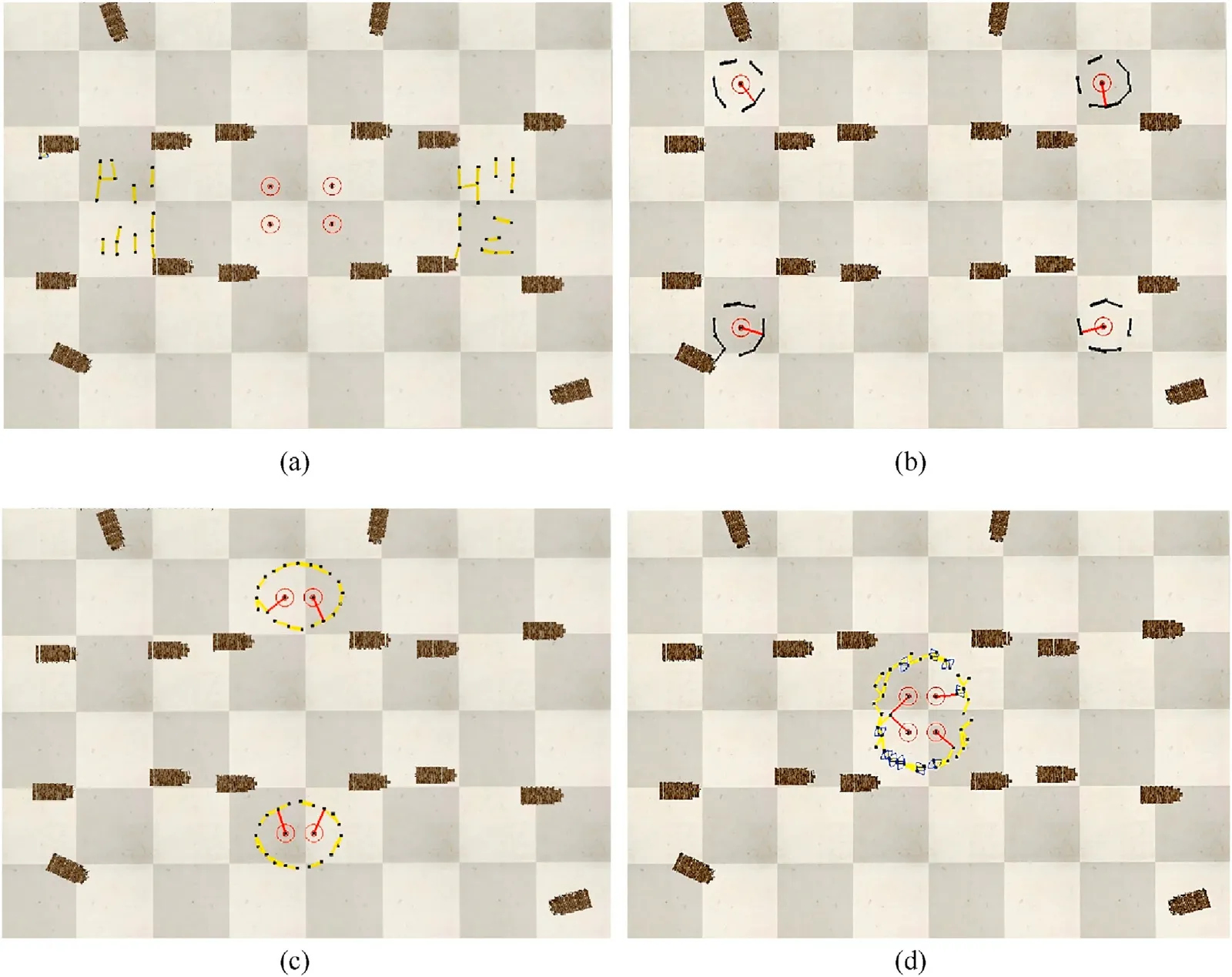
Fig.18.Forty drones trap four targets in the CoppeliaSim simulation: (a) Initial scenario; (b) Drones are divided into four groups to trap targets; (c) Drones are divided into two groups to trap targets; (d) Drones form a large circle to trap the four targets.
5.Conclusions
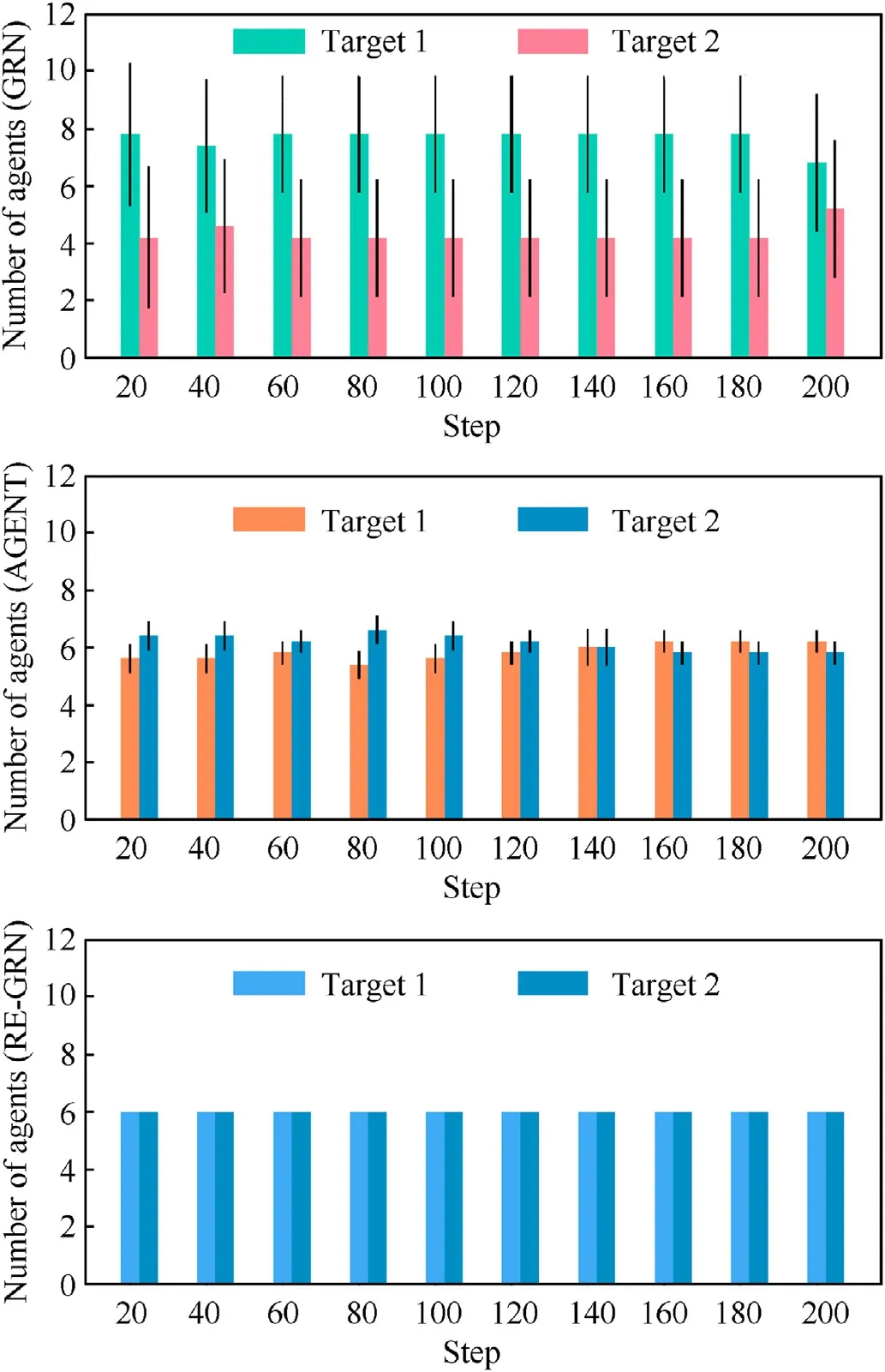
Fig.19.Uniformity of the division of robot groups.
The RE-GRN method proposed in this paper gives a novel idea of orbiting multiple targets while entrapping them in the military's application of the UAV swarm system.In this study, a three-layer algorithm framework is put forward to carry out environmental information transformation,adaptive decision making,and motion control respectively.Firstly, the concentration field of the information on the targets and obstacles is constructed to obtain the entrapping pattern.The designed decision mechanism then samples the entrapping pattern to generate capture points to form a uniform distribution of robots around the entrapping targets.The robots'orbiting the targets enables them to entrap the targets more tightly and effectively.Moreover,this study improves Vicsek-model to make robots more smoothly approach capture points.During this process, the robot can maintain the effect of collision-free flocking and obstacle avoidance.
According to the five experimental scenes in MATLAB experiments, robots by applying RE-GRN method can flexibly deal with varying complex obstacle scenarios, and change entrapping patterns adaptively to trap multiple targets while orbiting them.This study designed evaluation indexes considering entrapping task completion efficiency and the flocking effect.As shown in the evaluation indicators, the RE-GRN method outperforms the GRN method and AGENT method in the task of entrapping multiple targets, with a better encircling and revolving effect.Furthermore,we carried out simulation on the CoppeliaSim Simulation platform,which demonstrates that when entrapping multiple targets, the UAV swarm can effectively divide into groups and orbit the targets with a success.
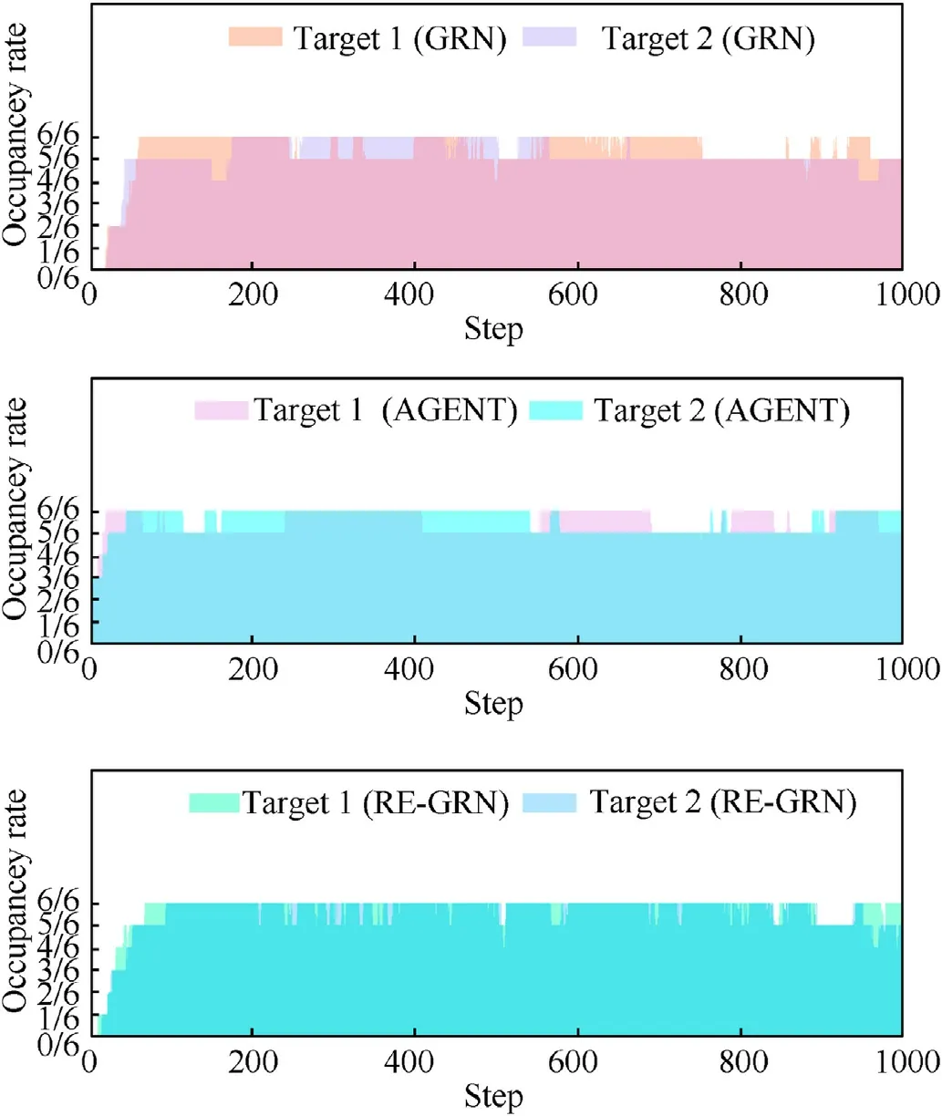
Fig.20.Robot occupancy rate of entrapment circle for each target.
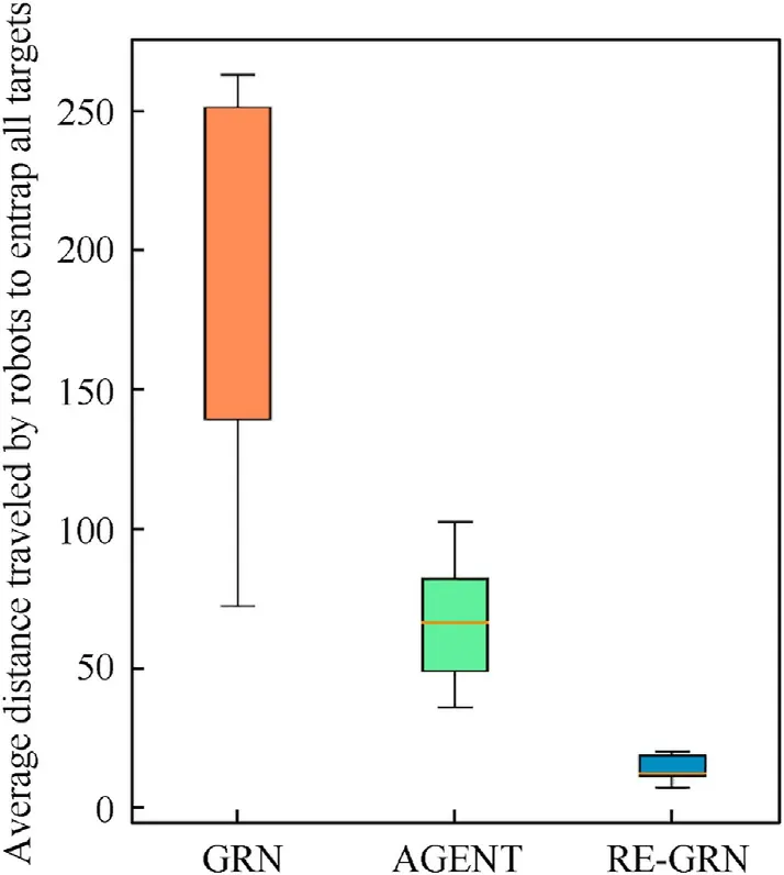
Fig.21.Average distance traveled by the robots to trap all the targets.
However,the proposed method relies on global communication,which is not conducive to the deployment of drones in nocommunication zones in military applications.Therefore, future studies aims to reduce the reliance of the method on communication.It is also very worthwhile to conduct physical experiments to validate the proposed RE-GRN algorithm.For this purpose, we have designed the prototype of individual swarm robots for 2D experiments and are developing UAV system for 3D experiments.This ongoing work will form the major part of the next step research.

Fig.22.Velocity correlation of robots at consecutive moments (GRN method).

Fig.23.Velocity correlation of robots at consecutive moments (AGENT method).

Fig.24.Velocity correlation of robots at consecutive moments (RE-GRN method).
Declaration of competing interest
The authors declare that they have no known competing financial interests or personal relationships that could have appeared to influence the work reported in this paper.
Acknowledgements
The authors would like to thank the Key Laboratory of Digital Signal and Image Processing of Guangdong Province, Shantou University,Guangdong Province,China,for the resources provided by them.This research is also is funded by the National Natural Science Foundation of China (62176147), the Science and Technology Planning Project of Guangdong Province of China,the State Key Lab of Digital Manufacturing Equipment and Technology(DMETKF2019020), and by the National Defense Technology Innovation Special Zone Project(193-A14-226-01-01).
Appendix
Matlab experiment video: https://www.bilibili.com/video/BV1eF41137Nm?spm_id_from=333.999.0.0.
CoppeliaSim simulation video: https://www.bilibili.com/video/BV1XF411W75e?spm_id_from=333.999.0.0.
- Defence Technology的其它文章
- The interaction between a shaped charge jet and a single moving plate
- Machine learning for predicting the outcome of terminal ballistics events
- Fabrication and characterization of multi-scale coated boron powders with improved combustion performance: A brief review
- Experimental research on the launching system of auxiliary charge with filter cartridge structure
- Dependence of impact regime boundaries on the initial temperatures of projectiles and targets
- Experimental and numerical study of hypervelocity impact damage on composite overwrapped pressure vessels