
Synthesis of Hierarchical Porous Fe2O3/Al2O3 Materials and Study on Catalytic Viscosity Reduction of Heavy Oil
2022-02-01 04:03WuPeiyueMaZhaofeiYangHaiyangXiongPanTanDichenYanXuemin
中国炼油与石油化工 2022年4期
Wu Peiyue; Ma Zhaofei; Yang Haiyang; Xiong Pan; Tan Dichen, Yan Xuemin
(College of Chemistry and Environmental Engineering, Yangtze University, Jingzhou, Hubei 434023, PR China)
Abstract: Fe2O3 nanoparticles were first dispersed in a sol solution containing an aluminum component introduced by an initial doping method. Composite catalyst Hierarchical Porous Fe2O3/Al2O3 materials (HPFA) were then synthesized through a sol-gel method via phase separation. The performance of HPFA was compared with that of Fe2O3 nanoparticle catalysts. The structure of the composite catalyst was characterized by scanning electron microscopy, X-ray diffraction, N2 adsorption/desorption, and crush strength testing. The results showed that the Fe2O3 nanoparticles could be loaded into the porous skeletons of Hierarchical Porous Al2O3 materials (HPA)to achieve a uniform dispersion while avoiding agglomeration, which improved the mechanical strength of the porous materials significantly. The HPFA was then used as a catalyst in the hydrothermal viscosity reduction process of Tuha heavy oil, and the viscosity reduction was investigated. The viscosity reduction rate of HPFA was 81%, which was better than that of the Fe2O3 nanoparticles (56%) and HPA (47%).
Key words: Fe2O3; initial doping method; hierarchical porous; heavy oil; viscosity reduction
1 Introduction
With the increasing demand for energy and the decreasing reserves of conventional crude oil, the contradiction between the supply and demand of oil is becoming more and more serious[1]. It has been surveyed and found that the reserves of heavy oil are huge, accounting for 70% of the world’s total oil reserves, and can provide sufficient power for global economic development, so many countries attach great importance to the exploitation and application of heavy oil research[2-4]. China is rich in heavy oil resources[5]. At present, the main methods of heavy oil extraction are thermal mining, physical viscosity reduction, chemical viscosity reduction, and other one or more methods used in conjunction[6]. Abroad, the use of circulating steam simulation (CCS), steam assisted gravity drive (SAGD), and horizontal well injection air catalytic modification (THAI-CAPRI) technology is prevalent[7-10].
At present, the main methods mainly used in the viscous reduction of heavy oil include surfactant emulsification and catalytic cracking. The aquathermolysis was used to describe the chemical interactions between heavy oil, water, and reservoir matrix under steam conditions (high temperature and pressure)[11]. Since the reservoir temperature decreases gradually with increasing distance from the wellbore after steam injection, it is difficult to maintain above 240 °C, resulting in insufficient energy supply for aquathermolysis reactions. Therefore, it is necessary to use catalysts in aquathermolysis reactions to improve the promotion technology, which can produce catalytic reactions under facilitation conditions. The use of catalysts in the aquathermolysis process facilitates the cracking of C–S, C–O, and C–N bonds at low temperatures, thus reducing the heavy hydrocarbons content and increasing the light hydrocarbons, which leads to a reduction in viscosity[12-16]. The key technology is the design and preparation of the catalysts, which mainly comprise oil-soluble catalysts, water-soluble catalysts, amphiphilic catalysts, ionic liquid catalysts, and nano-catalysts[17-23]. Among them, the nano catalyst has the advantages of small particle size, large specific surface area, and stable chemical properties. However, nano-catalysts have a strong adsorption capacity and tend to agglomerate. Therefore, in the process of preparing nano-catalysts, a hierarchical porous material with nano-scale mesopores and micro-scale macropores is provided as a carrier, so that the nano-catalyst is evenly distributed, thereby effectively avoiding the occurrence of agglomeration and further realizing the catalytic cracking of heavy oil[24-27].
Fe2O3nanoparticles (NPs) and Al2O3can be used as catalysts in the viscosity reduction reaction of heavy oil in aquathermolysis. The size of Fe2O3can reach the nanometer level, which has the advantages of smallsize, quantum-size, and surface effects[28]. Al2O3is widely used in the field of heavy oil lightening owing to its high strength, high activity, and other advantages[29-30]. Hierarchical Porous Al2O3material (HPA) containing a Y-type molecular sieve and a ZSM-5 molecular sieve has proved to be a good composite catalyst for heavy oil lightening. In this study, HPA was used as a carrier to synthesize Hierarchical Porous Fe2O3/Al2O3(HPFA) through the initial doping method. The structural properties of HPA and HPFA were analyzed, and applied in the viscosity reduction of heavy oil. The novel material is favorable to the viscosity reduction of heavy oil and provides a research direction for developing high-efficiency viscosity-reduction catalysts for the aquathermolysis of heavy oil.
2 Experimental
2.1 Chemicals
The reagents used for the experiments are shown in Table 1.
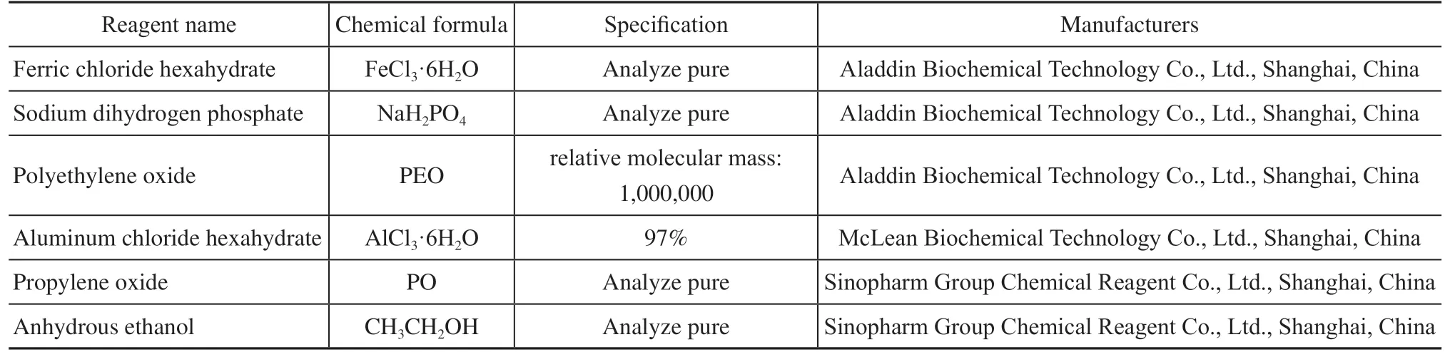
Table 1 Experimental reagents
2.2 Preparation of Fe2O3 NPs
In a typical procedure, 5.406 g of FeCl3·6H2O and 0.054 g of NaH2PO4were weighed and added to a beaker along with deionized water before stirring at room temperature for 20 min until being completely dissolved to prepare 75 mL of reaction solution. The solution was transferred to a 100 mL stainless steel autoclave, held at 105°C for 48 h and then cooled to room temperature. The product was moved into a centrifuge tube, centrifuged with a highspeed centrifuge (4500 r/s), washed with deionized water three times, separated, and precipitated. The precipitate was put into an oven (80 °C) and dried to obtain Fe2O3NPs for further use.
2.3 Preparation of hierarchical porous Al2O3 materials
First, 0.27 g of polyethylene oxide (PEO) powder was slowly added to 13.05 g of anhydrous ethanol. After full dispersion, a PEO dispersion was obtained. Then, 12.00 g of deionized water was slowly added into the dispersion, and the PEO was fully dissolved after stirring for 1 h. Next, 12.96 g of AlCl3·6H2O was added before stirring rapidly for 30 min under ice bath conditions until complete dissolution. Still under an ice bath, 9.33 g of PO was added continuously before vigorously stirring for 5 min to obtain a sol solution. The sol solution was poured into the sealed plastic tubes which contain many molds with Ф 5.0 mm × 80 mm, then sealed, moved to a 40 °C constant-temperature water bath, and aged for 24 h to obtain the wet gels. Removed the wet gels from the mold, and transferred to a constant-temperature drying box. After drying at 40 °C for 3 d, the wet gels became the dry gels, and the size shrunk to Ф 2.0 mm × 40 mm. In order to induce the Fe2O3NPs to be loaded, these dry gels were cut, and the size became Ф 2.0 mm × 8.0 mm. Finally, the catalyst was transferred to a muffle furnace and calcined at 800 °C for 2 h at a heating rate of 10 °C/min before naturally cooling to room temperature to obtain HPA for subsequent study[26-27].
2.4 Preparation of hierarchical porous Fe2O3/Al2O3 materials
The Fe2O3nanorods described in Section 2.1 (containing 10 wt% of the substrate material) were uniformly dispersed in 13.05 g of absolute ethanol, stirred for 5 min, and sonicated for 5 min to ultimately obtain a dispersion of Fe2O3NPs dispersed in absolute ethanol, which was denoted as EF. Then, 0.27 g of PEO was slowly added to EF to obtain a new dispersion, which was denoted as EFP. Next, 12.00 g of deionized water was weighed and slowly added to EFP, and the PEO was completely dissolved after stirring for 1 h. Then, 12.96 g of crystalline aluminum chloride was slowly added before rapidly stirring under ice bath conditions. After 30 min and complete dissolution, 9.33 g of PO was added, and a sol solution was obtained by vigorously stirring for 5 min. The sol solution was poured into a sealed test tube containing molds with dimensions of Ф 5.0 mm × 80 mm, sealed, moved to a 40 °C constant-temperature water bath, and aged for 24 h to obtain a wet gel. The coated film was removed, transferred to a constant-temperature drying box, and dried at 40 °C for 3 d to obtain small cylindrical dry gels via the same treatment method. Finally, the catalyst was transferred to a muffle furnace and calcined at 800 °C for 2 h at a heating rate of 10 °C/min before cooling to room temperature to obtain HPFA.
2.5 Characterization
The morphology of the catalysts was inspected using a scanning electron microscope (SEM, JSM-6150, JEOL Ltd., Tokyo, Japan) and a high-resolution TEM (FEI TalosF200s, Thermo Fisher Scientific, Massachusetts, USA). A two-dimensional elemental analysis was also performed using the SEM via energy-dispersive X-ray spectroscopy (EDS,JSM-6150, JEOL Ltd., Tokyo, Japan). The catalyst was also characterized by X-ray diffraction (XRD, Empyream, Cu/Kα radiation) under a scan speed of 10(°)/min. Nitrogen adsorption–desorption isotherms were measured at 77 K on a Micrometrics QUADRASORB SI (Quantachrome Instruments, USA) surface area analyzer and pore size analyzer; Before each nitrogen adsorption-desorption measurement, the samples were degassed at 573 K under vacuum for 3 h. The mesopore size distribution and mesopore surface area were calculated from the desorption branches using the Barrett–Joyner–Halenda (BJH) method, and the surface area was determined by the Brunauer–Emmett–Teller (BET) method. The macropore diameter was characterized using a mercury porosimeter (AutoPore IV 9520; Micromeritics Instruments Co., Georgia(USA)). The radial crush strength of the hierarchical porous materials was observed by an automatic particle strength determinator (KC-3T, Rhett Analysis Instrument Co., Ltd., China). Following a method similar to ASTM method 7084-4 (Standard Test Method for Determination of Bulk Crushing Strength of Catalysts and Catalyst Carriers),
The separated light components (saturates and aromatics) of the oil were measured by gas chromatographymass spectrometry (GC-MS, 7890A/5975C, Agilent Technologies Co. Ltd., Germany), and the heavy component was measured by Fourier-transform infrared spectroscopy (FTIR, Nicolet6700, Thermo Scientific™, USA). Refer to “SY/T 5119-2016 Analysis mothed for family composition of rock extracts and crude oil” to determine the family components before and after the reaction of heavy oil (i.e., saturates, aromatics, resins, and asphaltenes). More detailed information about the SARA analysis methodology was published previously[31].
2.6 Catalytic viscosity reduction for hydrothermal cracking of heavy oil
The viscosity reduction experiment was conducted in a 150mL autoclave. Tuha heavy oil was used as a reactant, with a viscosity of about 100,000 mPa·s at 50 °C. 60 g of oil sample (97280 mPa·s), 0.6 mL of tetralin (Shanghai McLean Biochemical Technology Co., Ltd.), 25 mL of deionized water, and 0.3 g of catalyst were added to the autoclave, and the reaction was carried out at 250 °C for 24 h. After the reaction reached completion, certain amounts of samples were taken from the sample cup, and their viscosity was measured after holding in a heating tank at 50 °C for 30 min.
3 Results and Discussion
3.1 Characterization of samples
3.1.1 SEM and TEM
Figure 1 shows SEM images of the micro-topography of the Fe2O3NPs, HPA, and HPFA (Fe2O3/Al2O3). The morphology of the Fe2O3NPs can be observed in Figure 1(a), which shows a grain spindle structure with a size of 200×50 nm2. In Figure 1(b–c), the morphology of HPA can be observed, which exhibits a coral structure with large pore channels. Figure 1(b) (inset) shows the appearance of a white monolithic HPA. In the magnified image in Figure 1(c), it can be observed that the particle surface is smooth. Figure 1(d) shows that the “corallike” structure of HPFA is still maintained, and Figure 1(d) (inset) shows the appearance of a reddish-brown monolithic HPFA. The magnified image in Figure 1(e) shows that the surface of the framework becomes rougher because the Fe2O3NPs were added into the supporter (HPA), and a granular structure appears to be dispersed in the cross section of the framework; these are the Fe2O3NPs, which are partially sintered after high-temperature calcination. The morphology of lighter and darker shades are also clearly identified by the TEM image in Figure 2(a), the Fe2O3NPs that have darker shades which have been dispersed inside of the Al2O3porous skeleton that have lighter shades. Thus, it was demonstrated that the Fe2O3NPs were successfully dispersed on the surface and inside of the hierarchical porous skeletons.
As seen in Figure 2(b), the Fe2O3NPs show an irregular shape with no-spindle-like Fe2O3observed, suggesting that there may be a sintering process between the Fe2O3NPs and the Al2O3monolith. The 0.27-nm interplanar distance shown in Figure 2(c) well matches the (104) interplanar distance of Fe2O3(JCPDS No. 33-0664), which also can be demonstrated by the XRD patterns in Figure 4.
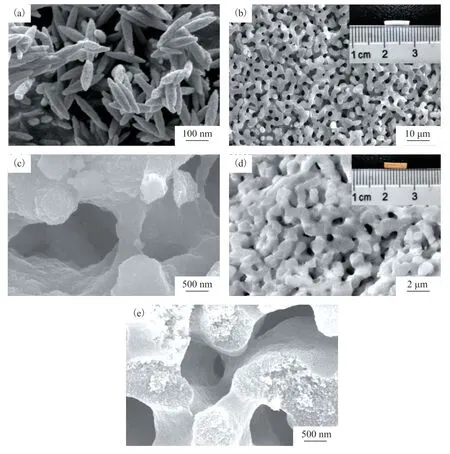
Figure 1 SEM images of (a) Fe2O3 NPs; (b–c) HPA, with the inset of (b) showing the appearance of a monolithic HPA; and (d–e) HPFA, with the inset of (d) showing appearance of a monolithic HPFA.
EDS mapping of HPFA is shown in Figure 3. Figure 3(a) shows the scanning range, Figure 3(b)(c) is a typical element distribution (Al, O, Fe), and Figure 3(d–f) show the mapping of Al, Fe, and O in the scanning range, respectively, where each element distribution can be observed. A porous skeleton structure of Al2O3composed of Al and O can be observed in Figure 3(d) and (f). A morphological distribution of the hierarchical porous structure is not clearly shown in Figure 3(e) because of the slightly lower addition of Fe, but it can be seen that Fe2O3NPs had been loaded into the hierarchical porous skeletons.
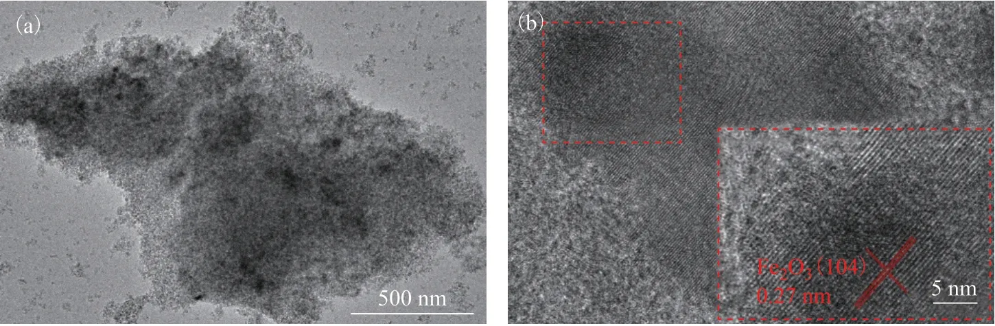
Figure 2 (a) TEM image of HPFA. (b) and inset (c) high-resolution TEM images of Fe2O3 NPs of HPFA.

Figure 3 (a, b, d, e, f) EDS mapping images of HPFA; (c) EDS plotof HPFA
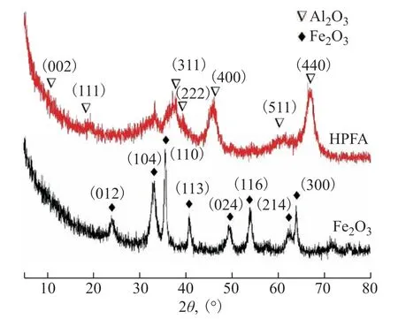
Figure 4 XRD analyses of HPFA and Fe2O3 NPs
3.1.2 XRD results
Figure4 shows X-ray diffraction patterns of the Fe2O3NPs and HPFA; the black line corresponds to the X-ray diffraction pattern of Fe2O3NPs. The characteristic diffraction peaks conform to the Fe2O3standard PDF card (JCPDS No. 33-0664), with no other impurity interference. Strong diffraction peaks appeared at 2θ= 33.1°, 35.6°, 54.1°, and 63.9°, and weak diffraction peaks appeared at 2θ= 24.1°, 40.8°, 49.4°, and 62.4°. The red line corresponds to the X-ray diffraction pattern of HPFA in which the characteristic diffraction peaks conform to be the γ-Al2O3according to the standard PDF card (JCPDS No. 10.0425). Strong diffraction peaks appeared at 2θ= 19.4°, 37.6°, 39.4°, 45.8°, and 67.0°, and weak diffraction peaks of the Fe2O3NPs were detected at 2θ= 33.1°, 35.6°, 40.8°, 49.4°, and 63.9°. The results showed that the Fe2O3NPs had weak diffraction peaks. Combined with the morphology characterization, it was confirmed that the Fe2O3NPs were doped into the Al2O3sol-gel solution by the initial doping method, and the two were successfully combined by phase separation, so that the Fe2O3NPs were distributed in the Al2O3porous skeletons to form HPFA.
3.1.3 Specific surface area and porosity
Figure 5 shows the macropore diameter distributions of HPFA measured using mercury porosimetry. The macropore diameter of HPFA was concentrated around 0.42 μm. Combined with the SEM images of Figure 1(d–e), it was determined that the addition of Fe2O3NPs did not destroy the macroporous skeleton of the hierarchical porous material.
Figure 6 shows the N2adsorption/desorption curves of HPA and HPFA. It can be seen that the low-pressure ends of the absorption/desorption curves were close to they-axis, indicating that the materials have interaction, which belongs to a type IV curve. The hysteresis loop was H2-type, belonging to porous adsorption, and the skeleton was formed by uniform particle accumulation or “ink-bottle,” which was consistent with the principle of hierarchical porous materials synthesis[26]. The BET surface area of HPA was about 223.8 m2/g, and that of HPFA was slightly smaller at about 170.5 m2/g. The pore properties of HPA and HPFA are summarized in Table 1. The synthesis principle of this material is the sol-gel method accompanied by the phase separation process[23]. According to the H2-type hysteresis loop shown in Figure 6, the pore structures of HPA and HPFA are formed by secondary particles of Al2O3accumulation. Before that, the secondary particles is formed bythe cross-linking of primary particles of Al2O3. And HPFA is formed by adding Fe2O3NPs before the formation of secondary particles of Al2O3[32].
Figure 7 shows the pore size distribution of HPA and HPFA obtained using the adsorption branches. The pore size of HPA was mostly distributed between 2–10 nm, whereas that of HPFA was mainly distributed between 2–20 nm. And Table 1 shows the BET surface area of HPA(223.8 m2/g) is larger than HPFA(170.5 m2/g). The pore size increases due to the addition of Fe2O3NPs that may occupy parts of the micropore space where secondary particles of Al2O3accumulate, and some Fe2O3NPs may strut open parts of the pore structure. This also leads to the BET surface area reduces, because the addition of Fe2O3NPs that may occupy parts of pores where secondary particles of Al2O3accumulate.
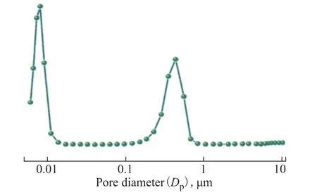
Figure 5 Macropore size distributions of HPFA
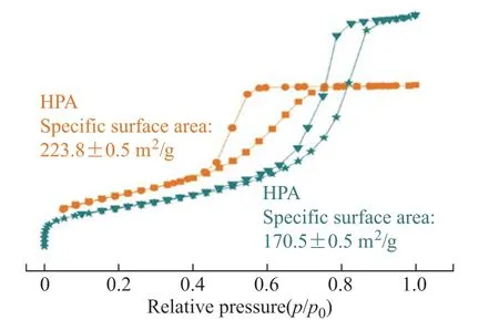
Figure 6 Nitrogen adsorption-desorption isotherms of HPA and HPFA

Figure 7 BJH pore size distribution curves of HPA and HPFA using the adsorption branches
3.1.4 Radial crush strength
The appearance of both HPA and HPFA was columnar, with dimensions of Ф 2.0 mm × 8.0 mm. The mean radial crush strength of the matrix material HPA was 93.8 N/cm. The radial crush strength test results of HPFA are shown in Table 2. Due to the addition of Fe2O3NPs, the radial crush strength of HPFA increased from 93.8 N/cm to 398.0 N/cm while retaining the three-dimensional macroporous skeletons and nano-sized mesoporous skeleton, which significantly increased the radial crush strength of the porous skeletons and is conducive to catalyst separation after the catalytic reaction.

Table 1 Pore properties of HPA and HPFA

Table 2 Radial crush strength test program results of HPFA
3.2 Catalytic viscosity reduction of heavy oil
3.2.1 Viscosity and content of SARA
The components present before and after the catalytic reaction of heavy oil were analyzed according to the SY/T 5119-2016 crude oil four-fraction separation test method, as shown in Table 3. The content of heavy components (resins and asphaltenes) was reduced after the heavy oil was catalyzed by different catalysts. Among them, the saturates of the heavy oil catalyzed by HPA increased by 0.1%, aromatics decreased by 0.6%, resins increased by 0.6%, and asphaltenes decreased by 0.1%. The saturates of the heavy oil catalyzed by the Fe2O3NPs increased by 0.6%, aromatics decreased by 0.63%, resins increased by 0.1%, and asphaltenes decreased by 0.2%. After being catalyzed by HPFA, the saturates increased by 2%, aromatics decreased by nearly 1.7%, resins decreased by about 1.9%, and asphaltenes decreased by 1.4%. Therefore, the catalytic effect of HPFA was better than that of HPA and the Fe2O3NPs.
Meanwhile, the viscosity of heavy oil was tested before and after the catalytic reaction, as shown in Table 4, the original viscosity of heavy oil was 97280 mPa⋅s at 50 °C test environment. The catalytic viscosity reduction effect with HPFA as catalyst was significant.
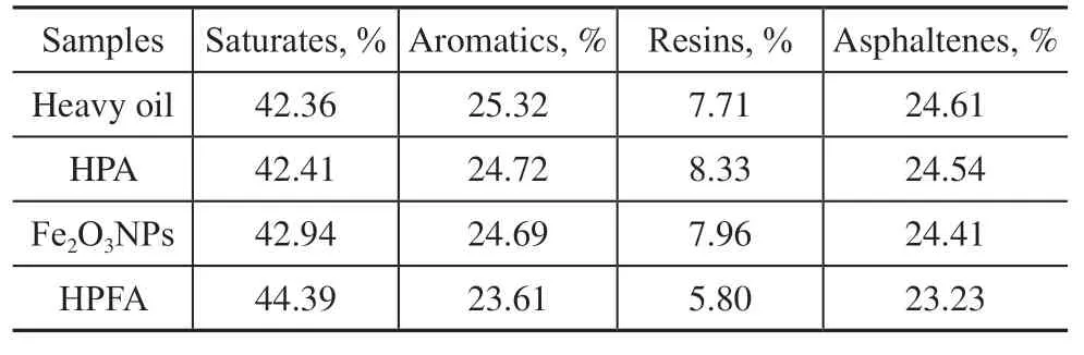
Table 3 Comparison of content of SARA before and after catalytic cracking
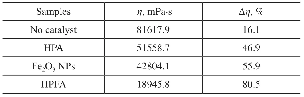
Table 4 The viscosity of heavy oil tested before and after catalytic cracking
In summary, among the three catalysts in the catalytic cracking process, the catalytic viscosity reduction effect is not high when HPA and Fe2O3NPs are used as catalysts separately, while the HPFA catalyst obtained by compounding the two can produce a better catalytic viscosity reduction effect. The reason is that HPA was only comprised of Al2O3with well-defined macropores and mesostructured skeletons, which is only a carrier material with relatively few active sites and insignificant catalytic performance. Therefore, the catalytic viscosity reduction effect was not obvious. The Fe2O3NPs had high catalytic activity, and Figure 1(a) also shows that although the NPs were high active, they were seriously agglomerated. However, the agglomeration seriously affected catalytic performance, resulting in no significant improvement of the viscosity reduction effect. However, after dispersing the NP in Al2O3material with the hierarchical porous skeleton and obtaining a composite catalyst of both, the oil viscosity was reduced from the original 97280 mPa⋅s to 18945.8 mPa⋅s, and the viscosity reduction effect was significantly improved nearly two-fold (as high as 80%).
Infrared spectra of the asphaltene and resin before and after the catalytic reaction by HPFA are shown in Figs. 8 and 9, respectively. The enhanced –CH2– and –CH3stretching vibrations at 2921 cm–1and 2850 cm–1, respectively, as well as the enhanced deformation vibrations of straight chain –CH and –CH– at 1457 cm–1and 1340 cm–1, respectively, in Figure 8 indicate that the asphaltene underwent ring-opening and hydrogenation reactions. Furthermore, the intensity of the characteristic absorption peaks of aromatic ring compounds at 650 cm–1to 900 cm–1was significantly weakened, indicating that the asphaltene underwent depolymerization reaction during hydrothermal cracking, leading to the depolymerization of thick-ringed aromatic hydrocarbons into small-molecule aromatic hydrocarbons.
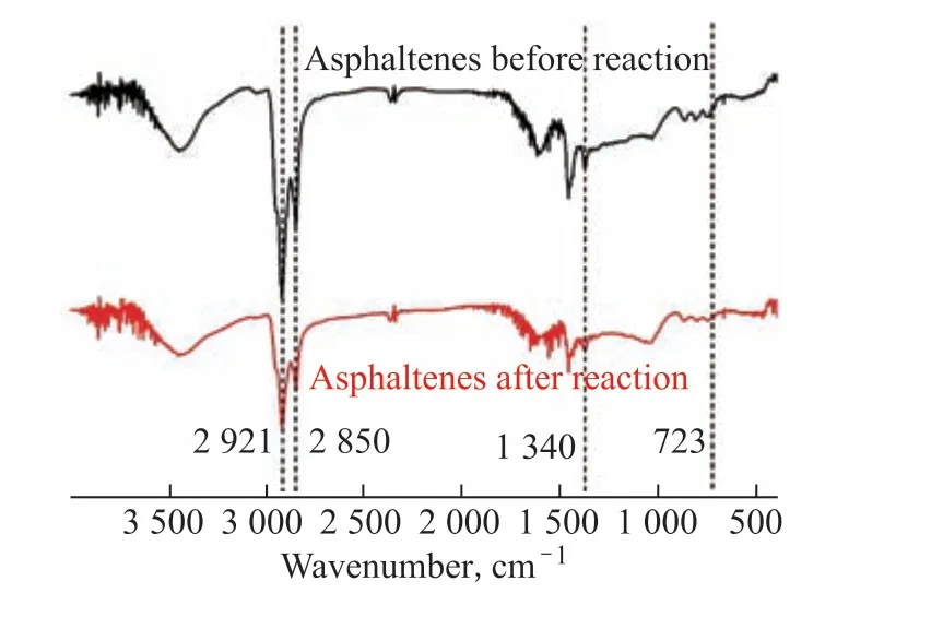
Figure 8 FT-IR spectra of asphaltene before and after the catalytic reaction by HPFA
In Figure 9, the enhanced deformation vibrations of straight chain –CH3and –CH2– at 1461 cm–1and 1380 cm–1indicate that hydrogenation occurred in the resin;the enhanced –C–H peak at 750 cm–1, the enhanced olefin characteristic absorption peak at 1680 cm–1compared to the crude oil resin, and the enhanced –C=O stretching vibration peak at 1739 cm–1indicate enhanced polarity and aromaticity in the reaction products and the oxygenation of the resin.
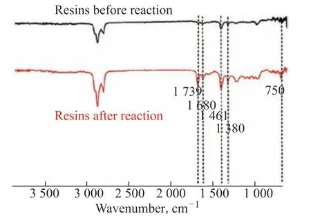
Figure 9 FT-IR spectra of resins before and after the catalytic reaction by HPFA
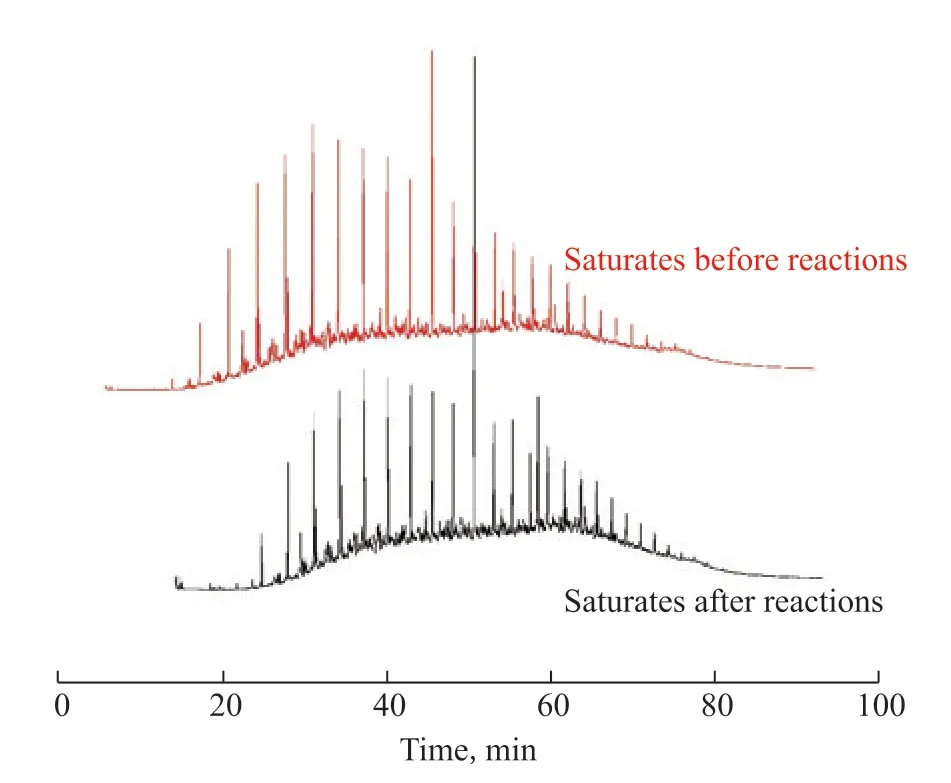
Figure 10 GC-MS of saturates before and after the catalytic reaction by HPFA
As shown in Figure 10, new peaks appeared in the heavy oil after catalytic reaction by HPFA for retention times below 15 min, indicating that there was hydrothermal cracking, which reduced viscosity; the large molecules in asphaltenes and resins were broken to generate new small molecules to increase the content of saturated hydrocarbons, thus reducing the viscosity of the heavy oil.As shown in Figure 11, the small-molecule peak heights were enhanced for retention times below 20 min (i.e., the small-molecule content increased), indicating that the large molecules in asphaltene were broken after hydrothermal cracking, and the thick-ringed aromatic hydrocarbons were depolymerized to produce new small molecules into the aromatic hydrocarbon fraction to increase the aromatic hydrocarbon content, which was consistent with the FT-IR results of asphaltenes.
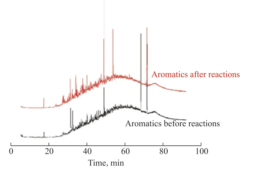
Figure 11 GC-MS of aromatics before and after the catalytic reaction by HPFA
Combined with the above data analyses and discussion, it was confirmed that the composite hierarchical porous material obtained by loading Fe2O3NPs into hierarchical porous Al2O3had a better catalytic effect on heavy oil catalytic cracking compared with Fe2O3NPs and HPA.
4 Conclusion
Using the initial doping method, self-made Fe2O3NPs were dispersed in an initial sol solution to synthesize an Al2O3hierarchical pore gel. Then, composite catalysts of HPFA were obtained via the sol–gel process accompanied by phase separation.
The Fe2O3NPs could be loaded into the porous material to achieve uniform dispersion and avoid agglomeration, and they did not damage the hierarchical porous structure. The composite catalyst could be then applied as an aquathermolysis catalyst in the viscosity reduction process of Tuha heavy oil, and the viscosity reduction rate could reach 80%, which was better than that of Fe2O3NPs (56%) and HPA (47%).
Acknowledgments:This investigation was supported by the National Natural Science Foundation of China (51472034) and the Cooperation Project of PetroChina Tuha Oilfield Company (2021H10005).
- 中国炼油与石油化工的其它文章
- Synthesis and Evaluation of Microporous Metal Organic Frameworks for Light Hydrocarbon Adsorption
- Removal of Basic and Non-Basic Nitrogen Compounds from Model Oil by FeCl3-Based Ionic Liquids
- Selection of Extraction Solvents for Bitumen from Indonesian Oil Sands through Solubility Parameters
- Activated Carbon from Rice Husk with One-Step KOH Mechanical Mixing Activation as Adsorbent for Treating Phenolic Wastewater
- Effect of Particle Shape on Catalyst Deactivation during 2-Butene and Isobutane Alkylation of Liquid Phase in Fixed-Bed Reactor Using Particle-Resolved CFD Simulation
- Experimental and Numerical Investigation on Erosion Corrosion of the Air Cooler Tube Bundle in a Residue Hydrotreating Unit