
Estimation of China Fusion Engineering Test Reactor performance and burning fraction in different pellet fueling scenarios by a multi-species radial transport model
2022-06-01 07:55WeishengLIN林伟胜XiaogangWANG王晓钢XueqiaoXU徐学桥DefengKONG孔德峰YuminWANG王嵎民JialeCHEN陈佳乐ZhanhuiWANG王占辉andChijieXIAO肖池阶
Plasma Science and Technology 2022年5期
Weisheng LIN(林伟胜),Xiaogang WANG(王晓钢),Xueqiao XU(徐学桥),Defeng KONG (孔德峰), Yumin WANG (王嵎民), Jiale CHEN (陈佳乐),Zhanhui WANG (王占辉) and Chijie XIAO (肖池阶)
1 State Key Lab of Nuclear Physics and Technology and School of Physics, Peking University, Beijing 100871, People’s Republic of China
2 Department of Physics, Institute of Space Environment and Matter Science, Harbin Institute of Technology, Harbin 150001, People’s Republic of China
3 Lawrence Livermore National Laboratory, Livermore, California 94551, United States of America
4 Institute of Plasma Physics, Chinese Academy of Sciences, Hefei 230031, People’s Republic of China
5 Southwestern Institute of Physics, Chengdu 610041, People’s Republic of China
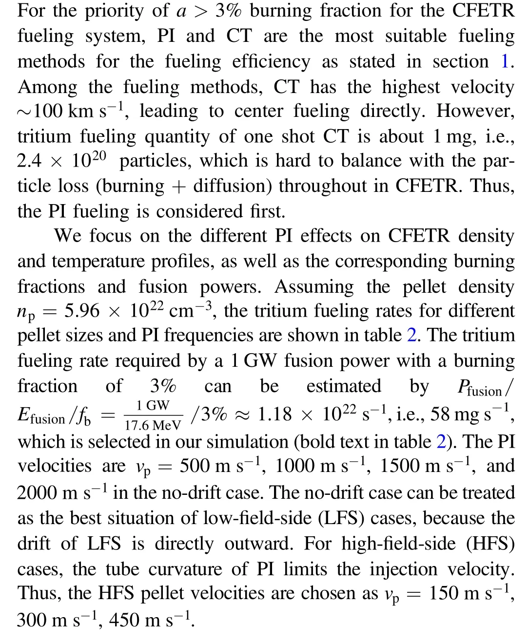
Abstract Tritium self-sufficiency in future deuterium-tritium fusion reactors is a crucial challenge.As an engineering test reactor, the China Fusion Engineering Test Reactor requires a burning fraction of 3%for the goal to test the accessibility to the future fusion plant.To self-consistently simulate burning plasmas with profile changes in pellet injection scenarios and to estimate the corresponding burning fraction, a one-dimensional multi-species radial transport model is developed in the BOUT++ framework.Several pellet-fueling scenarios are then tested in the model.The results show that the increased fueling depth improves the burning fraction by particle confinement improvement and fusion power increase.Nevertheless, by increasing the depth, the pellet cooling-down may significantly lower the temperature in the core region.Taking the density perturbation into consideration, the reasonable parameters of the fueling scenario in these simulations are estimated as pellet radiusrp = 3 mm,injection rate =4 Hz,and pellet injection velocity =1000-2000 m s- 1without drift or450 m s- 1with high-field-side drift.
Keywords: CFETR, tritium burning fraction, fueling scenarios
1.Introduction
Tritium self-sufficiency in future deuterium-tritium (DT)fusion reactors is a crucial challenge.The daily tritium consumption for a fully operated gigawatt (GW) fusion power station is of the order of 0.1 kg.Thus, current annual tritium production in the world can only support the operation of such a power station for approximately a couple of weeks.According to a recent tritium recycling model [1, 2], the burning fraction, which measures the percentage of tritium particles burned in one tritium cycle period,is a key factor for tritium self-sufficiency due to the low tritium breeding rate predicted.Furthermore, the startup quantity of tritium should be more than 10 kg if the burning fraction is only 1%.
Thus, besides sustaining a steady-state density profile in International Thermonuclear Experiment Reactor (ITER)scenarios, achieving a high burning fraction should also be a target for China Fusion Engineering Test Reactor (CFETR)[3] fueling scenarios.
In contrast to existing experimental facilities and ITER,CFETR requires a burning fraction of 3% for the goal to test the accessibility to the future fusion plant.The definition of the burning fraction isfb=ηfSfu/STf,whereSfuis the fusion rate,STfis the fueling rate of tritium particles,i.e.,the number of tritium particles that effectively reach the plasma core per second, andηfis the efficiency, making the fueling rate of tritium ionsSTf/ηf.Therefore, the way to improve the
The layout of the paper is as follows.In section 2, we first start from a zero-dimensional (0D) burning fraction model to make a magnitude estimation of the requirement for future reactor design.Then, a 1D radial transport model introduced in our previous work [12] is modified to take the temperature profile evolution into account and with the pellet deposition described by the neutral gas (NGS) and magnetohydrodynamic (MHD) drift model.This extended transport model with boundary conditions and CFETR parameters applied is described in section 3.The fueling scenario design, a short review of the pellet NGS-MHD model, and numerical results of different PI fueling scenarios are shown in section 4.Finally,a summary and discussion are presented in section 5.burning fraction can be proposed as follows.
(1) Improving the fueling efficiency.The fueling efficiencyηfof gas puffing (GP) [4], supersonic molecular beam injection (SMBI) [5], pellet injection (PI) [6], and compact torus (CT) injection [7] is about 1%-10%,10%-30%, >50%, and >50%, respectively.The difference between these fueling methods comes from the process that they experience.The GP and SMBI fueling methods are mainly by diffusion, while for PI the main processes are ablation and drift,and for CT the main process is magnetic reconnection.Due to their high fueling efficiency, PI and CT have become the most possible options for CFETR.In this work, we focus on pellet scenarios.
(2) Increasing the particle confinement time.Enhanced particle confinement was observed both in experiments and simulations by fueling in the core region by neutral beam injection(NBI)or high-speed PI[8,9].Typically,it was thought that the diffusion coefficient in the central core region is small,and thus central fueling can help increase the particle confinement.This makes the fueling depth a key factor in the CFETR fuel system design.
(3) Raising the energy confinement level.Besides sustaining the density, fueling is also a method to control burning plasma [10].For a GW fusion reactor, the schematic flowchart of particle and power flows of burning plasmas in tritium recycling is illustrated in figure 1.After the injection of PI or CT injected into plasma, the plasma density increases and the temperature decreases,which directly affects the alpha heating and the plasma confinement, withτE _98∝n0.41P-0.69,where n is the average density and P is the effective heating power.In fact, the interaction between alphas and background particles causes multi-scale spatialtemporal fluctuations [11].For simplicity, in this work,the interaction between them is represented byτE_98as illustrated in section 3.
Considering these factors to achieve a high tritium burning fraction thus becomes a key item for study in CFETR and other future DEMO operations.We then in this work selfconsistently simulate burning plasmas with profile changes in PI scenarios and estimate their burning fraction in a onedimensional (1D) multi-species radial transport model developed in the BOUT++ framework.Various pellet scenarios are tested in the model.The results show that the increased depth improves the burning fraction by particle confinement improvement and fusion power increase.Operation parameters for reasonable scenarios are also estimated.
2.0D burning fraction analysis
Before considering the complicated processes in burning plasma in the 1D simulation as shown in figure 1,a simple 0D analysis is used for magnitude analysis of the burning fraction in future reactor design.
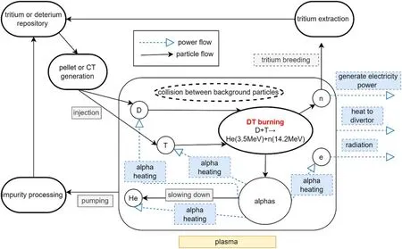
Figure 1.Illustration of the particle flow and energy flow in burning plasma tritium recycling.
Let us rewrite the definition of the ideal burning fraction as

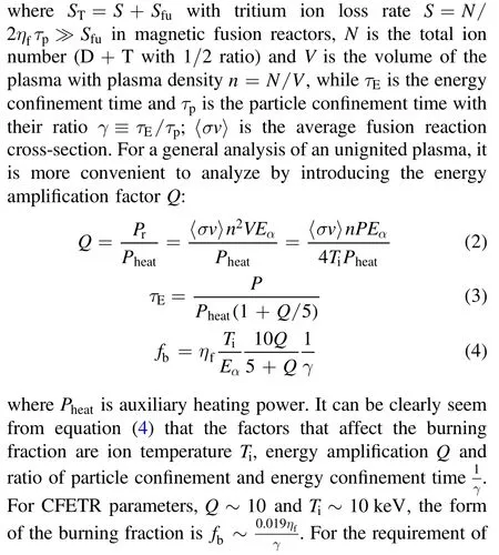

Although the 0D model sheds light on the way to improve the burning fraction, the profile effect and the inner link between theQ,Tiandcannot be described without the spatial transport.Moreover, the evolution of the density and temperature profiles during the fueling process needs to be taken into account.Therefore, a 1D radial transport model needs to be simulated to give reasonable fueling scenarios for CFETR.
3.1D transport model and numerical setups
3.1.Basic equations
As mentioned above, the burning plasma transport is a complicated problem taking fusion reaction and fuel source terms into account at the same time.Let us start from the collisional Boltzmann equation:
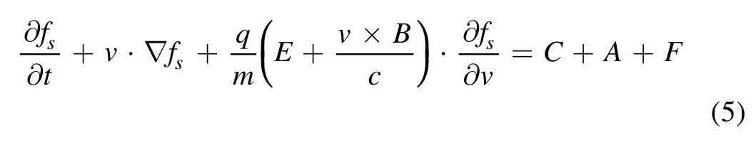
wheresstands for the different species andC,A, andFare the collision, fusion reaction and fueling source terms,respectively.
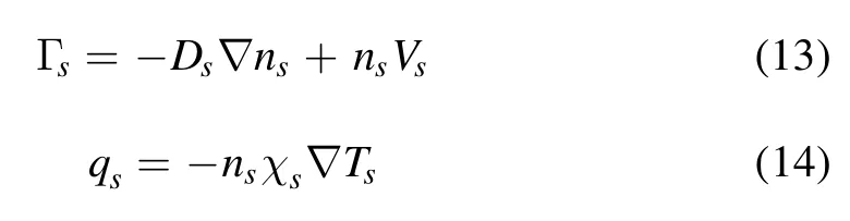
While the kinetic simulation is computational-time-consuming[13]and the momentum of the fueling source term is hardly estimated both in theory and experiment, the reduced Braginskii [14] equations are used in our model with source and sink terms due to fueling and fusion reaction.As introduced previously [12] and taking the thermal transport into account, the set of model equations is thus written:
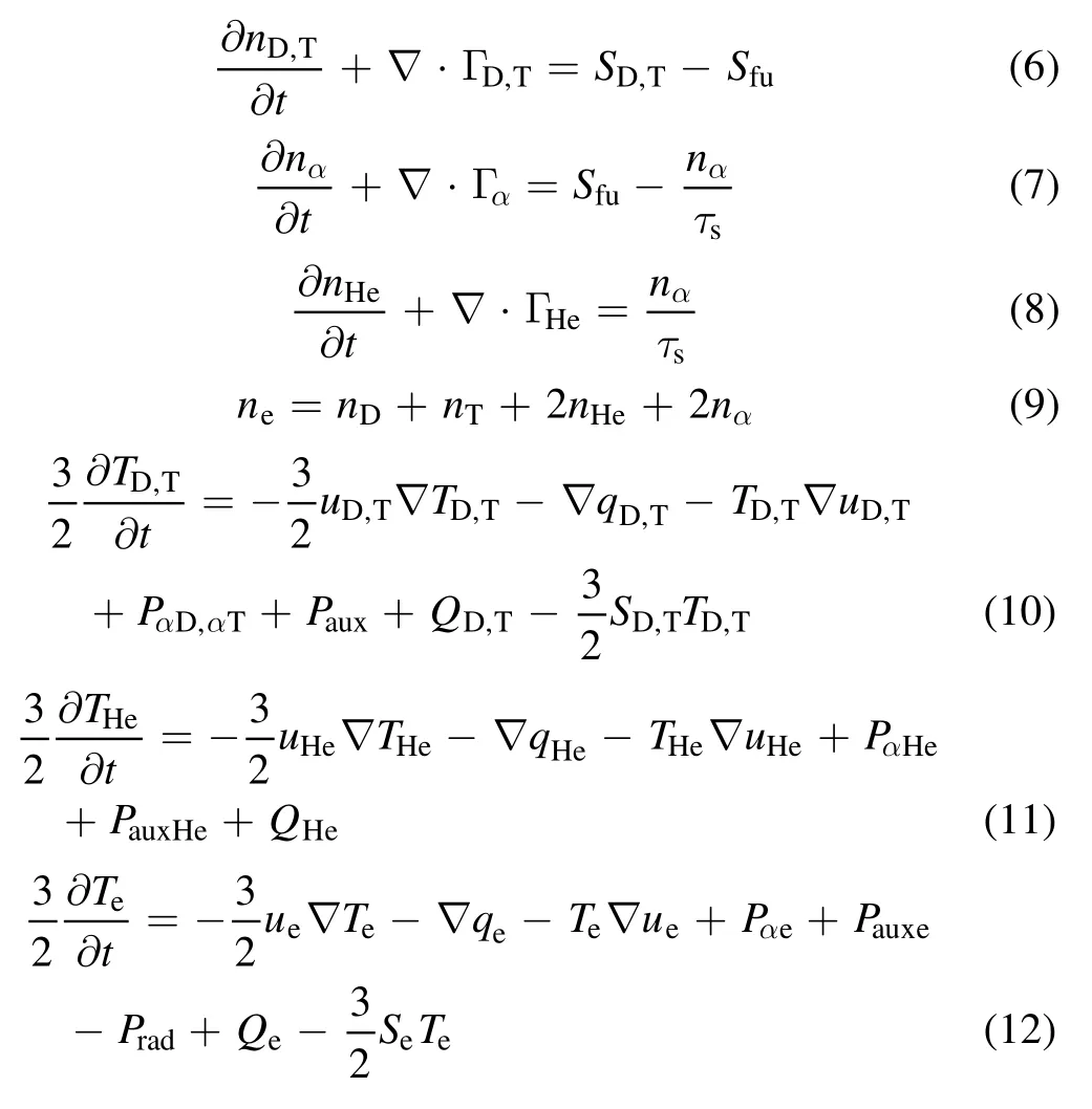
where the termSD,Tis the PI source term, as described in section 4.2.To explore the possibility of satisfying the burn fraction criterion, certain assumptions are made including 100%fueling efficiency and 50:50 deuterium to tritium ratio.The assumptions can be justified by high-density and temperature pedestals in designed edge-localized-mode(ELM)-free operations in CFETR and future reactors.Moreover, Pauxis the auxiliary heating power and the subscript stands for different species andSfu= nDnT〈 σv〉is the fusion loss term.The alpha particle classical slowing down theory[15] is consistent with Tokamak Fusion Test Reactor and Joint European Torus(JET)DT experiments without obvious alpha-particle-driven Alfvén eigenmode (AE) activities observed[16].This may not be the case for CFETR due to the large population of alphas and AE induced transport.However, in this work classical slowing down is used to describe alpha particle confinement in theory.The detailed formula for the slowing down time τs,alpha heating Pα, and heat transfer due to collisionQ are discussed in appendix.The particle flux Γ ,effective velocity u, and thermal flux q are illustrated as below.

Table 1.CFETR design parameters.
3.2.Setting for fluxes
To simplify the model,the form of species thermal flux is set as in the COREDIV CFETR simulation, for a CFETR 1 GW scenario profile calculated by OMFIT[17]with TGYRO[18]and TGLF [19].The setting for background thermal species(s = D, T, He, e) flux is then shown as below [20]:
The corresponding particle transport coefficient Ds,the heat conductivity χs,and the inward pinch velocityVsare then written

where the parameters A =0.1, ρ0= 0.92,p =100,Cei=1,Cv= 0.65,anda is the minor radius.The combination of alphas and thermal species in global transport is based on τE_ 98,where the fusion power and the effective mass enter the formula as follows [11]:

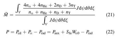
where Pαis the fusion power,Pcdis the current driven power,and Pradis the radiation power.The diffusion and pinch of alphas differ from those of the other species due to their isotropic velocity atWα0=3.5 MeV.The method of dealing with the alphas is based on the quasilinear model by Angioni et al for the study of turbulent transport of alphas and helium ash [21].The alpha particle diffusion and pinch can be expressed as

3.3.CFETR parameters and boundary condition
Several CFETR GW operation scenarios are designed in integrated modeling by the CFETR Physics Team[22].In this work, a GW hybrid scenario is applied and corresponding CFETR global parameters are shown in table 1.While the heavy impurity transport effect is not considered in this work,the impurity radiation power is taken into account and fixed in the simulation.The radiation and NBI heating power profiles are shown in figure 2.
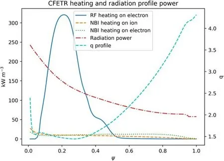
Figure 2.CFETR 1 GW hybrid scenario RF, NBI heating and radiation profile.
The simulation is conducted under the framework of BOUT++ [23] in the region of ψ = (0 .01, 1.0).The inner boundary condition is set as the Neumann condition for both plasma density and temperature.For the outer boundary condition,the density and temperature are kept at fixed values at the edge and the pinch velocity becomes zero for no edge particle inflow.The settings for the outer boundary are:

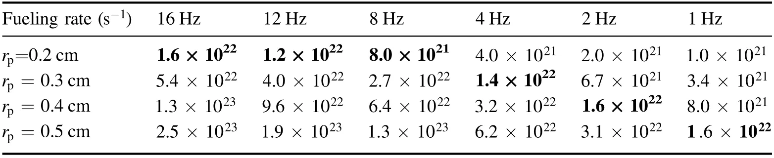
Table 2.Tritium fueling rate under different scenarios.
4.Simulation results of different fueling scenarios
4.1.Design of pellet fueling scenarios
The main PI processes are pellet ablation and deposition,as well as ablated material drift and parallel expansion [6].For the pellet deposition, the NGS model is used, which is widely verified by the International Pellet Ablation Database(IPADBASE) [24].The pellet deposition profile is then calculated by the NGS model as follows [25]:
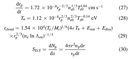
where T* stands for the temperature at the sonic radius and rcloudis the characteristic radius of the ablated cloud, and ,ϵ Eion,Ediss, and ln Λenare constants in our simulation.
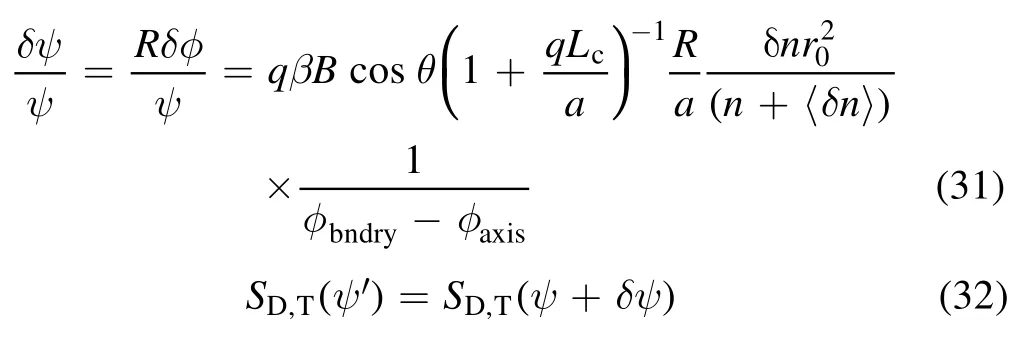
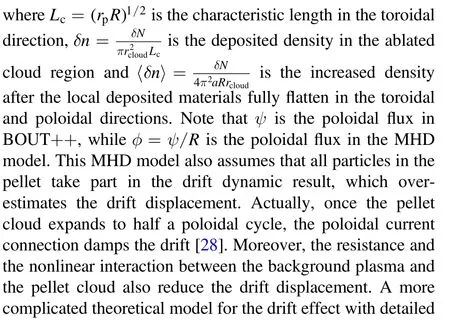
The drift phenomenon of ablated material is widely observed at ASDEX,JET,DIII-D and other tokamaks[6,26].The drift of the ablated cloud toward the major radius direction is related to the toroidal curvature, and the displacement due to the drift can be estimated by the MHD model [27] as:physics can be found in Park’s work [29].To avoid overestimating the drift effect, the damping factorb =2 is introduced,leading to δψ =δψ0(1 - e-b).The drifted source profile, i.e., equation (32), derives from the no-drift profile,i.e., equation (30), by changing the coordinate fromψ to ψ +δψ.
The time scale of parallel expansion is typically less than 1 ms, shorter than the radial profile transport time scale concerned.Thus the detailed parallel expansion process is not included in our simulation to reduce the problem into 1D.Based on these assumptions the simulation is carried out and the results are described as follows.
4.2.Size and drift effects of PI on profile evolution
Two typical cases are compared in this subsection, one for rp= 2 mm,f = 16 Hz,the other forrp= 5 mm,f =1 Hz,also with vp= 150 m s-1in the HFS and vp= 500 m s-1in the no-drift cases.Then, the total tritium fueling rate(the number of total particles injected per second) is almost the same in the two cases, as shown in table 2.It is clearly seen in figure 3(a) that the steady-state average electron density of therp= 5 mm scenarios is much higher than that of therp= 2 mm scenarios.In a pellet period,the fluctuation of the average density ofrp= 5 mm scenarios is about 2 × 10¹⁹m-3.However, the density fluctuation of the rp= 2 mm scenarios is ignorable for tokamak operation.Although the HFS inject velocity (vp= 150 m s-1) is lower than that of the no-drift case(vp= 500 m s-1),the densities at steady state in these two cases are similar.Relatively, the rp= 5 mm scenarios have lower steady-state temperature than therp= 2 mm scenarios as shown in figure 3(b).Due to the HFS inward drift,which makes the fuel directly lower the temperature at the center as shown in figure 3(c), the temperature of the HFS injected cases is much lower than that of the no-drift cases, and similar to the density perturbation, the rp= 5 mm pellet has a larger temperature perturbation of 1 keV than that forrp=2 mm.

Figure 3.2 mm,16 Hz pellet and 5 mm,1 Hz pellet cases when injected from different directions.(a)Electron averaged density,(b)electron averaged temperature, (c) pellet deposited profile, (d) maximum and minimum density profile at one pellet time when reaching the steady state and (e) maximum and minimum temperature profile at one pellet time when reaching the steady state.The pellet injected velocity is 500 m s-1 in the no-drift case (solid line) and 150 m s-1 in HFS (dash-dotted line).
To further estimate the influence of PI on profiles, different steady-state density and temperature profiles of one pellet with various sizes are plotted in figures 3(d) and (e).The maximum and minimum profiles clearly show the significant variations due to the pellet size.In general, the variations in density and temperature caused by the 5 mm pellet are larger than those by the 2 mm pellet.The HFS PI drift effect deepens the fueling position, which makes the HFS PI deposited profile more flattened and much less varied.Another interesting point is that although the no-drift 5 mm case only fuels at ψ > 0.8,it can still efficiently affect the central density as the HFS PI does, due to the large local density gradient caused by the bigger size (5 mm) of the pellet.We find that, in the 5 mm no-drift case, the lowest temperature profile almost has no pedestal.Therefore,further consideration is necessary for the 5 mm size PI to clarify the influence of the pedestal and related MHD instabilities.
4.3.PI depth under different fueling scenarios
As mentioned above, the fueling depth, i.e., the maximum depth at which the fuel penetrates, is a key parameter affecting the steady-state density and temperature profile.The investigation of the pellet fuel depth reached is shown in figure 4(a) (HFS) and figure 4(b) (no-drift) under different fueling scenarios.It can be seen in both figures 4(a) and (b)that the fuel depth has almost no dependence on frequency when the pellet size and velocity are fixed in these cases.As expected, the depth varies approximately linearly with the injection velocity.For the no-drift case,the fuel depth is only ρ ~ 0.2,even at vp= 2000 m s-1andrp= 5 mm,due to the high density and temperature pedestals of CFETR.Although the HFS PI velocity is much lower than that in the no-drift case, the HFS fueling deposition depth is much larger than that in the no-drift case.The key problem here is the pellet size.In this MHD theory, the drift displacement is proportional to particle quantities.Thus, the HFS drift features give rise to the possibility of deeper fueling into the central plasma region in future reactors.
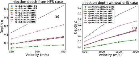
Figure 4.Injection maximum depth under different scenarios.(a) Injection depth of HFS (dash-dotted line), (b) injection depth of nodrift case.
4.4.CFETR performance and burning fraction in different fueling scenarios
According to the previous PI fueling experiments, a density could be achieved (0 .8 - 2.0) nGw[30] without disruption.For robust consideration, we chose the operation region of(0 .8 - 1.2) nGwin this work.Figure 5(a) shows the volumeaveraged electron density and volume-averaged ion temperature, and the green area is the safe operation region of 0.8 <nGw<1.2and T > 10 keV.Almost all therp=2 mm cases are located in the low-density but high-temperature region.On the other hand, the bigger size casesrp=4 mm andrp= 5 mm with high velocity or HFS injection may lower the temperature level to as low as 10 keV.It has to be pointed out,however,that though the low temperature may be a factor in decreasing the burning fraction,figure 5(b)shows a continuing increase in burning fraction with pellet size and velocity.To understand this trend, we revisit equation (4)where the burning fraction is shown to relate to Ti,γ ,and the factor 10Q / (5 + Q).Clearly, the effect of fusion power increase is insignificant.For a fusion power increase from 1 GW to 1.8 GW, i.e.Q = 12.5 to 22.5, the contribution of the factor 10Q / (5 + Q)to the burning fraction only rises from 7.14 to 8.18.Thus, as Tigets lower,is the only possible cause for the burning fraction increase, as clearly shown in figure 5(d).As the pellet size and velocity increase, 1/γ increases from 0.3 to 0.6, a remarkable improvement in particle confinement.
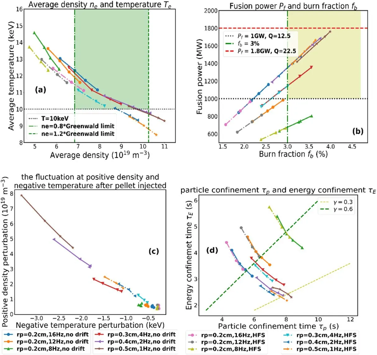
Figure 5.HFS(dash-dotted line),and no-drift(solid line)pellet scenario influence on CFETR.(a)Average density and temperature at steady state, (b) fusion power and burning fraction at steady state, (c) fluctuation at positive density and negative temperature after PI, and (d)particle confinement time and energy confinement time.The points from left to right are the results of500 m s -1, 1000 m s- 1, 1500 m s- 1,2000 m s- 1 in the no-drift cases and 150 m s- ,1300 m s- ,1450 m s- 1 in the HFS cases.
To find the practical fueling regime for CFETR, we further analyze the fueling scenarios using the 1D model.The region with >3% burning fraction and >1 GW fusion power is colored yellow in figure 5(b).Combining the green region in figure 5(a)and the yellow region in figure 5(b),the suitable fueling scenarios for CFETR in these simulations are rp= 3 mm, 4 Hz,1000 - 2000 m s-1,no-drift;rp=5 mm,1 Hz,500 m s-1,no-drift;rp= 3 mm, 4 Hz,450 m s-1,HFS.
However, as shown in figure 3(c), the large pellet perturbation on profiles is unfavored for operation.Figure 5(c) shows the positive difference between the maximum and mean densities locally and the corresponding negative temperature difference.Therp= 5 mm PI causes a density perturbation>4 × 10¹⁹m-3,making these fueling scenarios unacceptable.Thus, it seems that one may get only a very narrow parameter regime for CFETR fueling design.However, if we lower the fusion energy gain Q, i.e., either by increasing the auxiliary heating power or by reducing the fusion power expectation,the burning fraction criterion can then be much more easily achieved.
5.Conclusions and discussion
In summary, this paper offers a 0D analysis for the burning fraction criterion and a 1D simulation for favorable fueling scenarios of CFTER, which can also be applied to future DEMOs and fusion power stations.We start from the 0D burning fraction requirement to make a magnitude estimation for reactor design.Then,a 1D transport model evolving both density and temperature profiles at the same time is developed,with NGS and MHD drift models for PI fueling, based on the framework of BOUT++.Several fueling scenarios are analyzed to test the designed CFETR burning fraction and performance for 1 GW cases.For the PI fueling, at a rate of~1.8 × 10²²s-1,cases for a pellet size from 2 mm to 5 mm with an injection velocity from 500 m s-1to 2000 m s-1of no drift and 150 m s-1to 450 m s-1of HFS injection are simulated.The main conclusions from the numerical simulation for CFETR design parameters are as follows:
(a) In the 0D analysis, the unfavored fueling efficiency or unfavored particle confinement makes the burning fraction requirement hard to achieve.
(b) In the 1D transport simulation, the fueling depth has almost no dependence on the PI frequency, when the fueling rate is in a certain range, and the fueling depth varies approximately linearly with the injection velocity, even with the drift being taken into account.In comparison with the no-drift case, the HFS drift makes the pellet penetrate deeper even with a slower velocity.
(c) For the 1D transport, the bigger pellet size and higher velocity can certainly increase the density but reduce the temperature, and the contribution to the burning fraction improvement by increasing pellet size and velocity mainly comes from the improvement of particle confinement.
(d) In 1D transport simulation, the practical fueling scenario that considers the reasonable burning fraction,high density, high fusion power, and small density perturbation isrp= 3 mm, 4 Hz,no drift, 1000-2000 m s-1or HFS 450 m s-.1 Although certain optimistic assumptions such as 100%fueling efficiency have been made,the 1D model used in this work is still applicable for first-step analysis in CFETR fueling scenarios.Nevertheless, according to the simulation result, only a narrow region has been found in the parameter space for CFETR pellet fueling scenarios.It thus requires further efforts to improve the model with better approximations and detailed physics, as well as interaction with the background plasma, such as pellet triggered ELMs.
Acknowledgments
This work is supported by National Natural Science Foundation of China (Nos.11975087 and 41674165) and the National Key Research and Development Program of China(Nos.2017YFE0300501 and 2018YFE030310).
Appendix A
According to classical slowing down theory, the slowing down time can be estimated:

wherefα(Wα)is the energy distribution of alpha, and the classical heat transport time can be calculated:
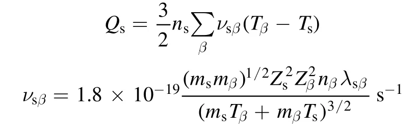
The alpha heating powers on an electron and a background ion (take D as an example) are as follows:
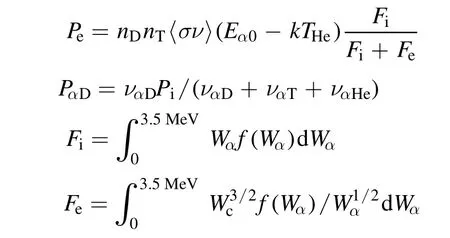
whereWα0=3.5 MeV is the alpha born energy.
 Plasma Science and Technology2022年5期
- Plasma Science and Technology的其它文章
- Synthesis of Ag-decorated vertical graphene nanosheets and their electrocatalytic efficiencies
- Upgrade of an integrated Langmuir probe system on the closed divertor target plates in the HL-2A tokamak
- Numerical study of atmospheric-pressure argon plasma jet propagating into ambient nitrogen
- Effects of O2 addition on the plasma uniformity and reactivity of Ar DBD excited by ns pulsed and AC power supplies
- Design and first result of combined Langmuir-magnetic probe on J-TEXT tokamak
- Selective catalytic reduction of NOx with NH3 assisted by non-thermal plasma over CeMnZrOx@TiO2 core-shell catalyst