
Two-dimensional self-consistent numerical simulation of the whole discharge region in an atmospheric argon arc
2022-06-01 07:55ZelongZHANG张泽龙ChengWANG王城QiangSUN孙强andWeidongXIA夏维东
Plasma Science and Technology 2022年5期
关键词:孙强
Zelong ZHANG (张泽龙), Cheng WANG (王城), Qiang SUN (孙强)and Weidong XIA (夏维东)
1 Anhui Advanced Technology Research Institute of Green Building, Hefei 230601, People’s Republic of China
2 Department of Thermal Science and Energy Engineering,University of Science and Technology of China,Hefei 230027, People’s Republic of China
Abstract A 2D self-consistent numerical model of the whole argon-arc discharge region that includes electrodes is developed in this work to facilitate analysis of the physical processes occurring in atmospheric arc plasma.The 2D arc column model contains the ionization and thermal nonequilibrium,which is coupled with a 1D electrode sheath model.The influence of plasma-species diffusion near the electrode region is investigated based on Maxwell-Stefan equations and the generalized Ohm’s law.The numerical results of argon free-burning arcs at atmospheric pressure are then investigated.The simulation shows that the plasma is obviously in the state of thermal and ionization equilibrium in the arc core region, while it deviates from thermal and ionization equilibrium in the arc fringe region.The actual electron density decreases rapidly in the nearanode and near-cathode regions due to non-equilibrium ionization, resulting in a large electron number gradient in these regions.The results indicate that electron diffusion has an important role in the near-cathode and near-anode regions.When the anode arc root gradually contracts,it is easy to obtain a positive voltage drop of the anode sheath(I = 50 A),while it remains difficult to acquire a positive anode sheath voltage drop(I = 150 A).The current-voltage characteristics predicted by our model are found to be identical to the experimental values.
Keywords: ionization non-equilibrium, thermal non-equilibrium, electron diffusion, arc discharge
Nomenclature

1.Introduction
Arc plasma is widely applied in numerous industrial fields due to its characteristics of high temperature, enthalpy, and chemical activity [1].As many parameters in the arc discharge process are difficult to measure directly, numerical simulations are employed to understand the process.The interaction between the electrode and the arc column plays an important role in arc discharge.As a result,the near-electrode plasma layers of atmospheric- and high-pressure arc discharges have been the focus of research over the past 40 years[2-5].
Cathode phenomena, which are extremely complicated,are traditionally thought to determine the existence of arc plasma discharge.Consequently, the near-cathode plasma layer has been the focus of research [5-17].An important contribution was made by Benilov et al [6, 7, 18], who established the non-linear cathode surface heating model.This model was widely accepted as it could obtain multiple cathode root modes that were consistent with experimental results.Wang et al developed a two-dimensional (2D) rotary axisymmetric mode, including hydrodynamic equations and heat transfer equation, which considers surface evaporation and Joule heating [19, 20].Baeva et al [8, 21] developed a chemical non-equilibrium model of the arc column, which was directly coupled with a cathode sheath.A review of nearcathode plasma layer modeling can be found in[22].In recent decades,the near-anode plasma layer has attracted increasing attention due to the expansion of basic research and anode applications [23-30].As is known, the near-anode region is usually affected by the flow of the arc column,and the electric field near the anode region is usually reversed because of the diffusion current [24, 26].Therefore, the study of the nearanode plasma layer needs to be coupled with the arc column,and non-equilibrium ionization should be considered to investigate the influence of the diffusion current on the nearanode region [21, 26].In addition, scholars have recently begun to study the effects of the anode sheath further[25-28].
At present, most research only considers specific aspects of arc plasma, such as the near-cathode region, arc column,and near-anode region.However, the best way to understand the physical process of arc discharge is to simulate the whole cathode and anode region,simultaneously.Almeida et al[31]established a near-cathode layer unified model for an arc plasma at high pressure without any simplifying assumptions.The above-mentioned one-dimensional model was then used by Khrabry et al[32,33]to study the entire arc discharge area to determine the pressure of the argon short arc.Due to the inclusion of assumptions in the entire near-electrode region,the unified model has only been used in one-dimensional arc mode at high pressure until now.However, one-dimensional modeling cannot predict the radial distribution of current density, heat flux, and other parameters in the near cathode and near anode layers.
A 2D cathode-arc column-anode whole argon-arc model was recently developed by Baeva et al [21], whose diffusion current was obtained by Maxwell-Stefan equations, and the characteristics of current-voltage obtained by the model were highly consistent with the experimental results.This work mainly focused on the plasma-cathode interaction.Some simplifications were used in the near-anode region; for example,the simulations were performed with the assumption that the anode sheath voltage was zero.
While the study of arc plasma has made significant progress,a global coupling model of the whole arc discharge region is still required to investigate the physical processes occurring near the electrode and arc column region.Therefore, a self-consistent numerical model of the whole arc discharge region that includes electrodes is required.In this study, a self-consistent model is established to formulate the whole arc discharge physical process.A 2D arc column model containing the ionization and thermal non-equilibrium is presented, which is combined with a 1D electrode sheath model in an atmospheric-pressure argon free-burning arc.Two different ion and electron dynamics mechanisms for the cathode and anode sheath model are used to account for the different anode sheath voltages.The near-electrode region plasma species diffusion is investigated based on Maxwell-Stefan equations and generalized Ohm’s law in much greater detail.
The rest of this paper is structured as follows.In section 2, a detailed description of the model and its governing equations are given.The models include an arc column model and a sheath model.The numerical implementation is described in section 3, including the results and discussion.We also explore the characteristics of the cathode sheath, arc column, and anode sheath.Finally, the conclusions are presented in section 4.
2.Numerical model
Figure 1 displays the schematic diagram of the global coupling model in the whole arc discharge region.To study the influence of diffusion current on the near-electrode region,both the thermal and ionization non-equilibria are considered in the 2D arc column model.According to the approach developed by Baeva et al[8,21],the ionization layer and the arc column can be considered as a whole.Consequently, the interfaces between the electrodes and the arc column only consist of the near-electrode space-charge sheath,displayed in figure 1.

Figure 1.Schematic diagram of the coupled model.
2.1.The model of the arc column
In this study, the state of the arc column deviates from the thermal and ionization equilibria.Atoms, electrons, and singly charged ions are considered when the electron temperature is below 22000 K [34].
Continuity equation:

Momentum conservation equation:

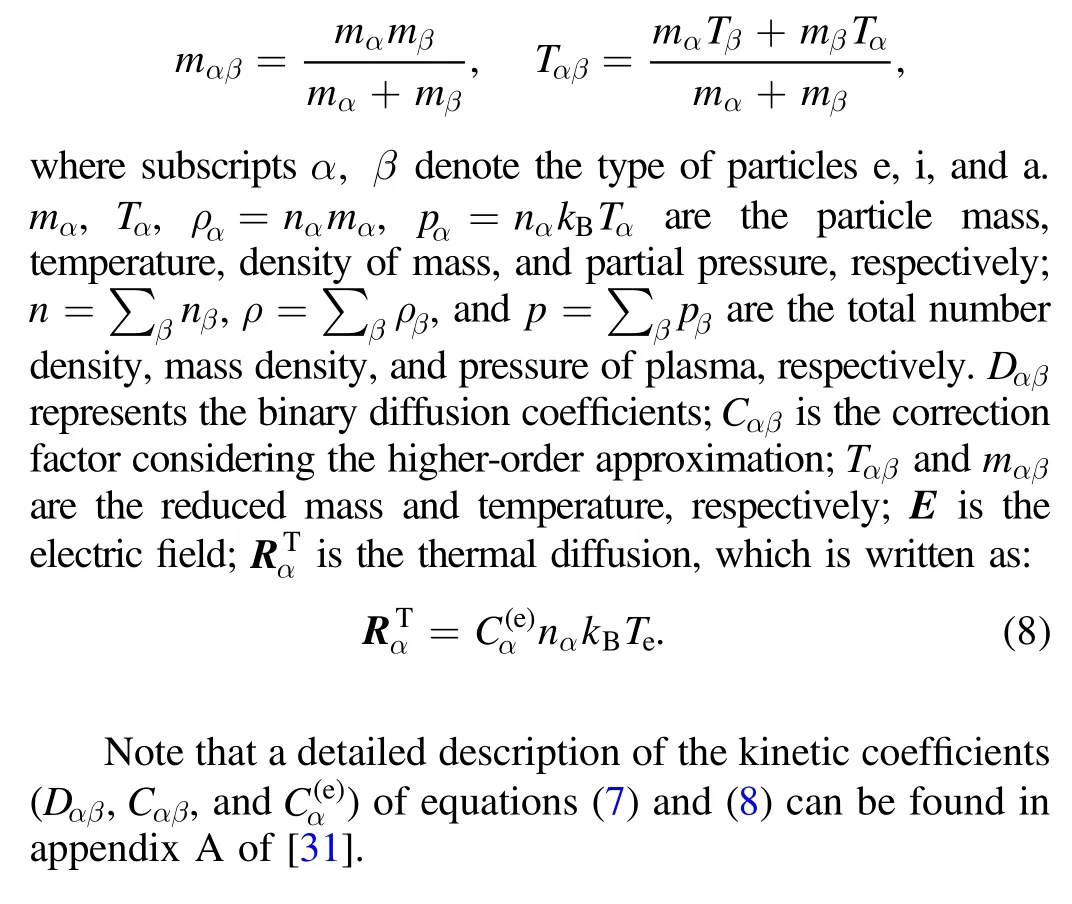
whereρandpare the mass density and pressure of the gas,respectively.Vis flow velocity,I,τ,jandBare the identity matrix, viscous stress tensor, current density, and magnetic field, respectively.
2.1.1.Species conservation equations.The transport equation for each species is

For the speciesα,Jα=nα vαis the number density flux.Here,nαandvαare the number density and mean velocity;n˙αis the net rate of the production;i, e anda represent the ion,electron, and atoms, respectively.The net generation rate of speciesαis:

wherekiandkrare the coefficients of ionization and recombination, respectively.Adding the species conservation equation for ions and atoms and subtracting the species conservation equation for ions and electrons, the following relations are obtained:

whereJi-Je=j/e,jis the current density, andJa+Ji= const = 0[30].
The calculation of the number density fulx(Jα=nαvα) of species is highly significant in multi-component systems(electrons, ions, and atoms).Note that the fluxJαincludes the convective and diffusion terms (i.e.,Jα=nαV+nα(vα-V)).In this work, the number density fluxes of plasma components are obtained using the Maxwell-Stefan equation [35]:
where
2.1.2.Energy conservation equations.For electrons:

For heavy particles:

whereheandhhpare the heat flux densities of electrons and heavy particles, respectively.QelandQinare the energy transferred between electrons and heavy particles due to the elastic collisions and the electron energy loss caused by inelastic collisions, respectively.The expressions of elastic and inelastic collisions are:

whereEionis the ionization energy of the argon atom.
The heat fluxesheandhhpcan be expressed as the heat conduction and the inverse to thermal diffusion, respectively[31]:
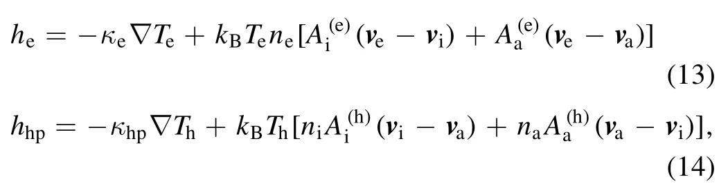
whereκhpandκerepresent the thermal conductivity of the heavy particles and thermal conductivity of the electrons,respectively.andare the kinetic coefficients.A detailed description of the above transport and kinetic coefficients can be found in appendix A of [31].
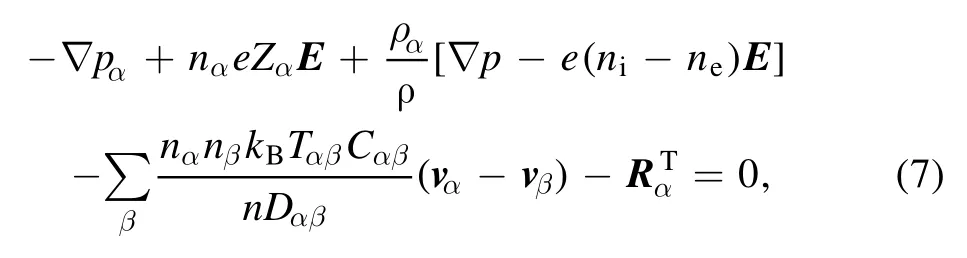
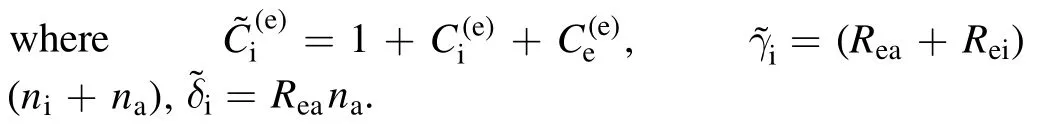
Further, according to [28],vaandviare eliminated from the Maxwell-Stefan equation(equation (7)) for electrons and ions using equations (5) and (6).

where
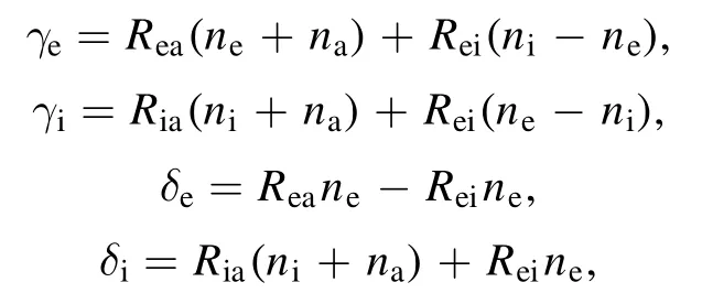
The equations for ions and electrons are added(equation (15)) according to the quasi-neutrality assumptionne=ni,and then the ion number density fluxJican be obtained.Finally, this expression ofJiis substituted into the species conservation equation of ions to obtain the following equation for the ion number density:

The total pressure of the arc plasma is the sum of the pressures of the plasma components (ions, electrons, and atoms), i.e.

The atom number density in this model can be obtained by equation (17), and the electric field is calculated by the Maxwell-Stefan equation of the electron.
2.1.3.Generalized Ohm’s law.The current density is given:
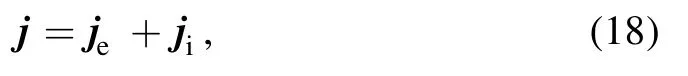
wherejis the current density,je= -eJeis the electron density, andji=eJiis the ion current density.
Maxwell’s equation:

whereAis the magnetic vector potential, andμ0is the permeability of the vacuum.
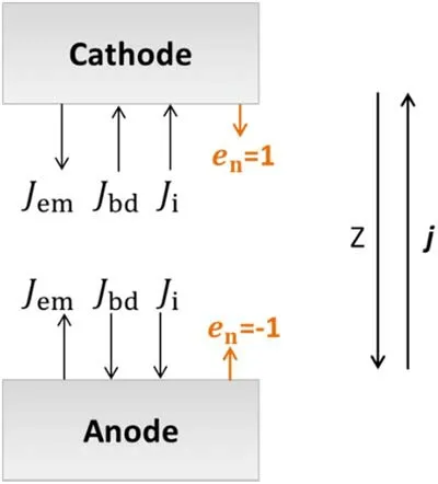
Figure 2.Schematic diagram of current composition on the electrode surface.
2.2.The sheath model
As shown in figure 2,the current density in the near-electrode space sheath can be expressed as:

whereJemis the number density flux of thermionic emission electron,jionis the number density flux of ions, andJbdis number density flux of the back-diffusion plasma electrons.Here,subscript b is related to the boundary of the plasma and electrode, anden,brepresents the projection of a unit normal on the Z-axis of the outer surface of the electrode.
For the hot cathode, the total current density is [20]:

wherejem,jion,andjbdare three different current densities,respectively.jemis caused by the thermionic emission of the electron,jionis delivered to the electrode surface by ions,andjbdis transported from the plasma to the electrode by backdiffusion plasma electrons.Here
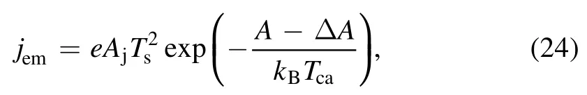
whereAjis the Richardson’s constant,A is the work function of electrode material,ΔAis the Schottky correction toA,andTsis the surface temperature of the electrode.
The model for the anode sheath has differences with the cathode sheath.For the water-cooled anode studied in this work, there is no emission electron, i.e.jem= 0.Therefore,the total current density of the anode (according to equation (22)) is:

Due to the one-dimensional assumption of the space charge sheath, all physical quantities describing the sheath layer are set as scalars.
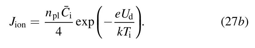
For the cathode or negative anode sheaths (Ud< 0), the sheath will hold back the electrons.Therefore, the electron density reaching the electrode is [36]:
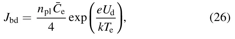
wherenplis the electron density at the plasma-sheath interface, andis the average thermal speed of electrons.
Ions freely reach the anode without impediment from the negative voltage of the anode sheath,whose density reaching the electron is:

The positive anode sheath (Ud> 0) combines with the electron flow impeding ions to the anode.Thus, the electron density reaching the anode is:

and the ion density reaching the anode is:
For the cathode, the electron heat flux of the plasmacathode boundary can be expressed as:

For the anode,Jem= 0,and the electron heat flux of the plasma-anode boundary can be written as:

According to[31],the heat flux to the electrode from the plasma of the arc column is as follows:

wherehhpis expressed as equation (14).
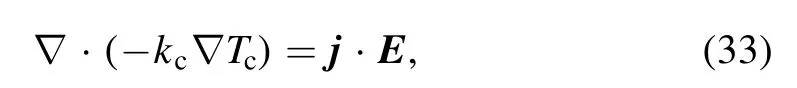
For the anode, heat transfer equation is solved in the anode body and reads:

wherekais the thermal conductivity of anode materials, andTais the anode temperature.In the anode body,the equations of electric potential and magnetic vector potential are same as those given in equations (19)-(21).
For the cathode, heat transfer equation is solved in the cathode body and reads:
wherekcis the thermal conductivity of anode materials, andTcis the anode temperature.In the cathode body, theequations of electric potential and magnetic vector potential are same as those given in equations (19)-(21).
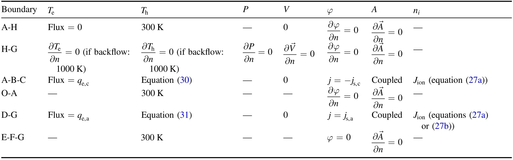
Table 1.Boundary conditions.
2.3.Calculation domain and boundary conditions
An argon-arc sketch is provided in figure 3.The gap between the cathode and anode is 10 mm, and the cathode (tungsten material) is a cylindrical rod (1 mm radius) with a hemispherical tip.The water-cooled anode (copper material) has a 25 mm radius, with a 3 mm wall thickness corresponding to[37].Both the cathode bottom and the anode outer part are 300 K ambient temperature, and table 1 shows the boundary conditions.The conditions of axial symmetric are employed at O-C-D-E, and A-H is the wall, where a 300 K heavy particle temperature is assumed.At E-F-G, which is the anode bottom and right, the potential is set to 0, and a 300 K temperature is given.At H-G, a constant temperature backflow (1000 K) is given to the zero gradients of each primary variable.
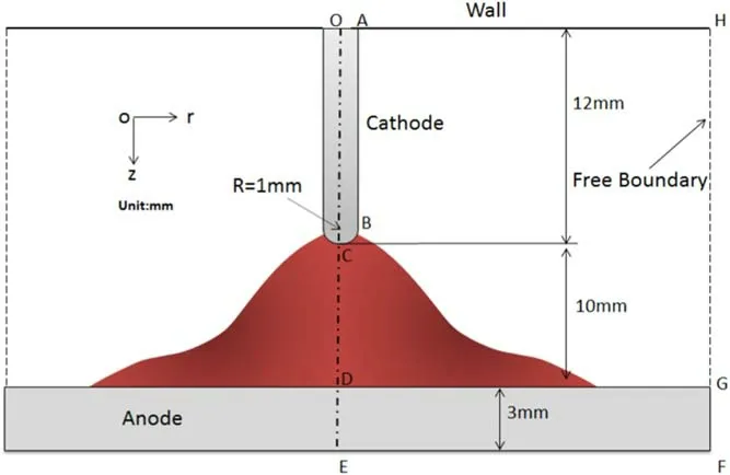
Figure 3.Sketch of the geometry.
The surface of the cathode(A-B-C)and the surface of the anode (D-G) are the interfaces between the near electrode and the sheath.Based on[6],the boundary condition ofjis applied on A-B-C and D-G.Here is an example of the cathode boundary (A-B-C).Assuming that other variables in the arc column have been solved, thenjs,candqs,cin equations (23)and(30)are only a function of the cathode surface temperatureTcand the cathode voltage dropU.cThe cathode surface temperature can be determined byqs,c.Therefore, integrating the current density (js,c) of cathode surface A-B-C, one will find the arc current of 100 A corresponding to a value ofUcbeing considered.The boundary conditions for the current density,ion flux,electron temperature,and total energy flux in the sheath region are described in detail in the sheath model of section 2.2, as shown in table 1.
The non-equilibrium anode model is simulated using the computational fluid dynamics software Fluent with userdefined C++ language.The grid has approximately 250 000 cells.The unstructured mesh is used near the tip of the hemispherical cathode, and the structured mesh is used in other areas.Due to the strong ionization non-equilibrium near the cathode tip and near the anode, parameter gradients are very steep.A refined resolution with a 0.00125 mm minimum grid size is employed in the region near the anode and cathode surfaces, where the parametric gradient was steep.
3.Results and discussions
3.1.Characteristics of arc column plasma
Figure 4 shows the heavy particle temperature distributions of the whole calculation domain, including the cathode and anode.As illustrated in the figure, the temperature at the cathode tip is about 3800 K,and the temperature at the anode surface is slightly higher than 300 K.It can be observed that the temperature of the heavy particles increases first,reaches a maximum in the front of the cathode tip, and then decreases.Figure 5 shows the distributions of electron and heavy-particle temperatures along the arc axis for different arc currents(I = 150 A,and I = 50 A).In the arc core region,the plasma is obviously in the state of thermal equilibrium, while it deviates from thermal equilibrium in the arc fringe region.The maximum values of electron temperatures (20000 K for I = 150 A, and 18000 K for I = 50 A) appear at the cathode surface, while the maximum values of heavy-particle temperatures(17500 K for I = 150 A,and 15000 K for I = 50 A)appear at a certain distance from the cathode surface.
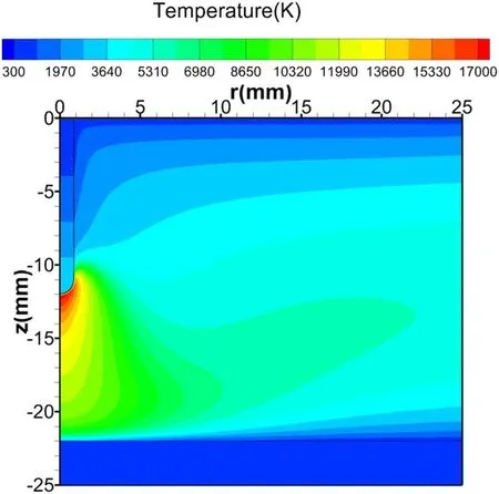
Figure 4.The distributions of heavy-particle temperatures for I = 150 A.
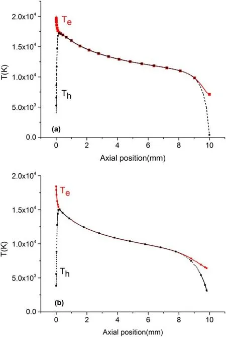
Figure 5.The distributions of electron and heavy-particle temperatures along the arc axis (CD).(a) I = 150 A; (b) I = 50 A.
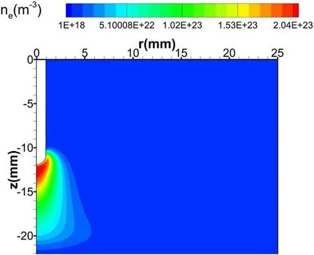
Figure 6.The distribution of electron density for I = 150 A.
The distribution of electron density for I = 150 A is shown in figure 6.It can be seen that the calculated maximum of electron density is about2.04 × 1023m-3and occurs in front of the cathode surface.The electron density distribution is a bell shape, which is similar to the shape of the temperature.Figures 7 and 8 show the electron density distribution along the arc axis (CD) for I = 150 A, and I = 50 A,respectively.ne(n on) is the electron number density calculated by our model, andne(s aha) is the electron number density in ionization equilibrium(i.e.Saha equilibrium)in the figures.As shown in figure 7, in the central region of the arc column(1-9 mm in the axial position),the calculated electron densities obviously satisfy the Saha equilibrium; that is, the plasma is in the ionization equilibrium state, while the ionization equilibrium breaks down in the near-electrode region.As illustrated in figure 8, the ionization non-equilibrium region will expand with the decline of the arc current,especially at the anode.Figures 7 and 8 also show that the plasma density in Saha(ionization)equilibriumne(s aha)near the cathode increases rapidly, which is due to the electron temperature increasing rapidly near the cathode (as shown in figure 5).However, the actual plasma density calculated by our modelne(n on) rapidly decreases in the near-cathode region because of non-equilibrium ionization.The deviation between the actual plasma density and the Saha equilibrium plasma density is more than one order of magnitude and reaches a maximum on the cathode surface.This is mainly due to a large number of ions and electrons recombining on the surface of the cathode.Near the anode region, due to the decrease of electron temperature(as displayed in figure 5),the actual plasma density will also decrease because of the net recombination of ions occurring.Moreover,the actual plasma densityne(n on) is higher than the Saha equilibrium plasma densityne(s aha) .

Figure 7.The distributions of electron density along the arc axis(CD)for I = 150 A.(a)The whole arc region;(b)the near-cathode region.
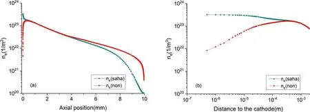
Figure 8.The distributions of electron density along the arc axis (CD) for I = 50 A.(a) The whole arc region; (b) the near-cathode region.
Figure 9 shows the electric field distribution along the arc axis(CD)for I = 150 A.It can be seen that the absolute value of the electric field near the cathode reaches up toV m-1, which leads to a rapid rise of electron temperature near the cathode.Note here that the calculated electric field is actually the electric field in the ionization layer, and the electric field in the cathode sheath should be larger than that in the ionization layer.It can also be observed that the electric field near the anode will reverse, which is caused by the diffusion current.The diffusion phenomenon near the anode region is an important physical mechanism that has been discussed in detail in previous works [21, 26].The absolute value of the electric field near the anode can reach a maximum of4 × 105V m-1, while the electric field in the nearanode region is much lower than that in the near-cathode region.This indicates that the energy stored in the near-anode layer is much less than that in the near-cathode layer.
Figure 10 shows the current density distributions along the arc axis(CD)when current I is 150 A.It can be seen that the magnitudes of the diffusion and ohmic currents are much larger than the total current density near electrodes regions.Near the cathode region, js,cis in the opposite direction to the diffusion current, and the absolute value of the diffusion current density is larger than js,c.Therefore, for the conservation of js,c,the electric field and Ohmic current rises sharply near the cathode region, and their directions are the same as js,c,as shown in figures 9(b) and 10(b).It can be observed that the diffusion phenomenon in the near-cathode region is also important and leads to a rapid increase of the electric field and Ohmic current near the cathode(as shown in figure 9(b)).In the region close to the anode, the diffusion current density has the same direction as js,a,while the absolute value of diffusion current density is higher than js,a.Therefore,the electric field and ohmic current near the anode region will reverse to maintain the conservation of total current density, as shown in figures 9(c) and 10(c).
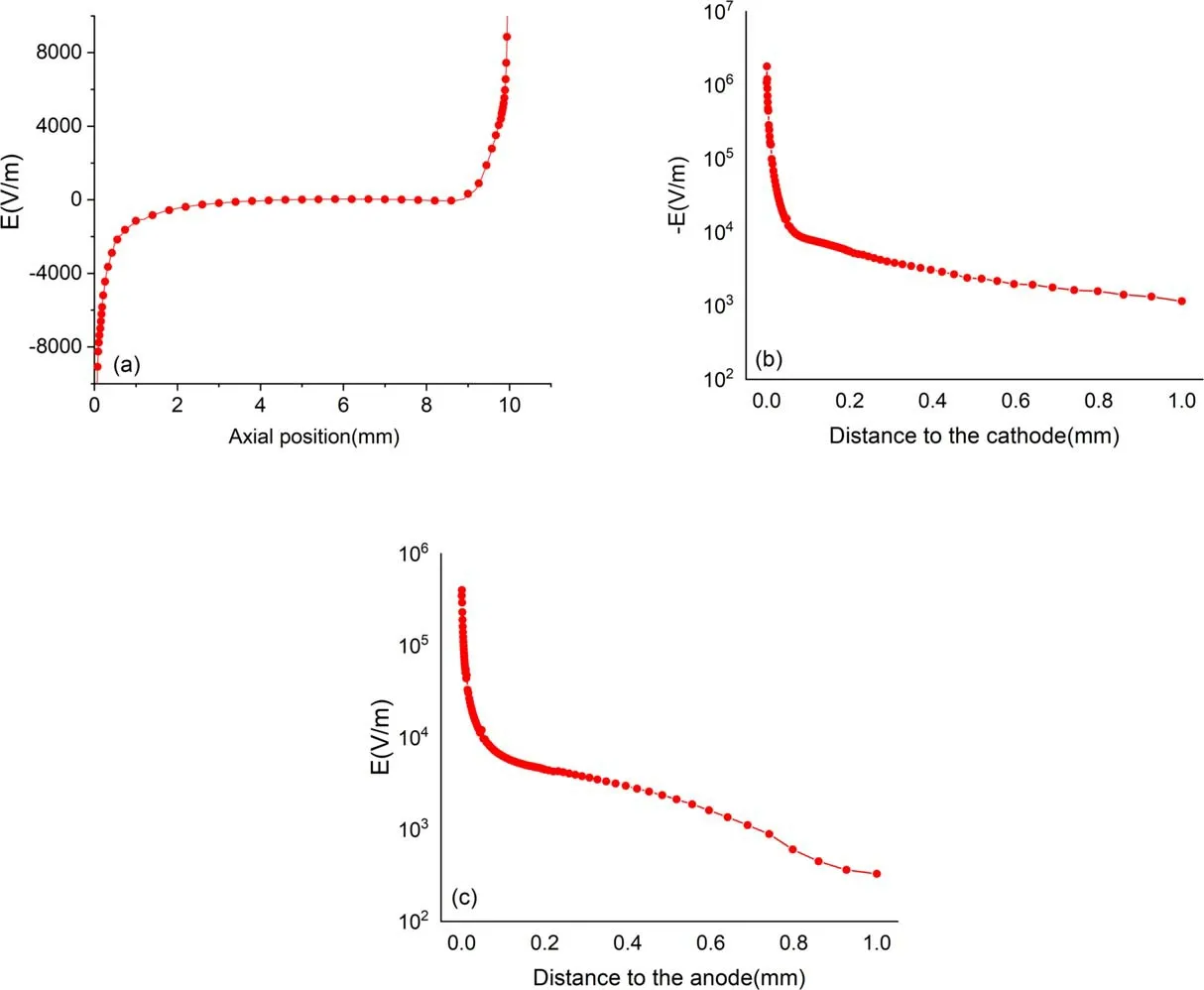
Figure 9.The distributions of electric field along the arc axis(CD)for I = 150 A.(a)The whole arc region;(b)the near-cathode region;(c)the near-anode region.

Figure 10.The distributions of current density along the arc axis(CD) for I = 150 A.(a) The whole arc region; (b) the near-cathode region;(c)the near-anode region.(jo hm :Ohmic current density; jd iff :diffusion current density; jt ot :total current density).
Finally,we can see that the diffusion phenomenon in the near electrode region is mainly produced by non-equilibrium ionization, which causes the actual electron density to decrease rapidly near the anode and cathode regions.This results in a large gradient of electron numbers in these regions,meaning that electron diffusion will play a significant role here.Moreover, the current generated by electron diffusion near the anode region is in the same direction as the total current, leading to a reversal of the electric field, while the current generated by electron diffusion in the near-cathode region is in the opposite direction to the total current,leading to an increase in the electric field.
3.2.Characteristics of the cathode and anode sheath
Figure 11 shows the distribution of current density for I = 150 A along the cathode surface.On the cathode surface,the current density of electron emission (jem) far exceeds the current density of back-diffusion electrons (jbd) and the current density of ions (jion).Therefore, the current density of electron emissions (jem) is the main contribution of the cathode surface.Figure 12 shows the distribution of current density for I = 150 A along the anode surface.On the anode surface, the electron current density (je) from the quasi-neutral plasma is two orders of magnitude larger than the ion current density (ji).Thus, the anode current is predominantly maintained by the electron current.As the cathode sheath has always been the focus of previous studies, we do not expand on this topic here.The mechanism of the anodic sheath is discussed in detail subsequently.
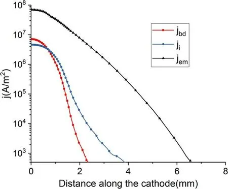
Figure 11.The distribution of current density along the C-B-A surface for I = 150 A.
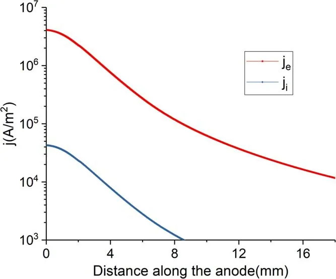
Figure 12.The distribution of current density along the cathode surface for I = 150 A.
Figure 13 display the current-voltage characteristics of the anode sheath for the diffused anodic root.When the anode arc root is in the diffused state, the voltage drop of the anode sheath is negative for different arc currents.As the negative anode sheath will hinder the electrons, the electron current density reaching the anode will reduce.It is also found that the absolute value of the voltage drop of the anode sheath decreases with the reduction of the arc current.As both anode roots calculated by our model are diffused for different currents, it is difficult to obtain a positive anode sheath without any limitations.Previous research has struggled to calculate the contracted anode root self-consistently,while the diffused arc root has been easy to obtain.According to the latest research[38,39], a more complete chemical non-equilibrium model,which considers the excited atoms and molecular ions of argon, is needed to self-consistently calculate the contracted anode arc roots.
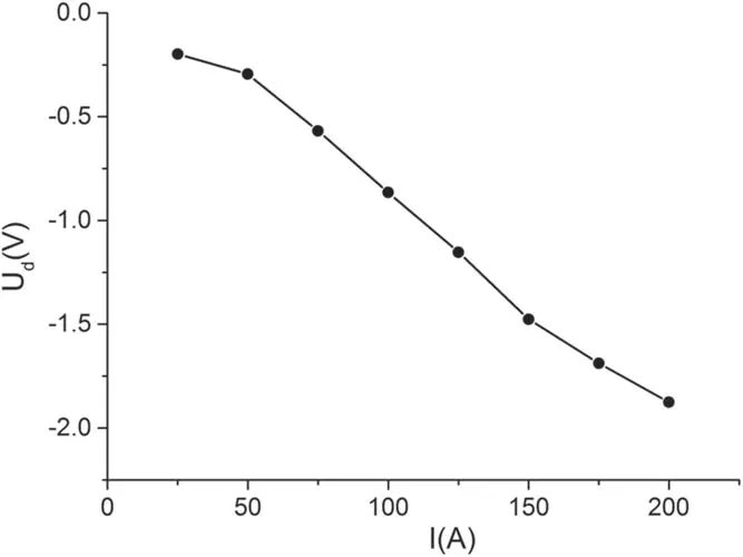
Figure 13.Current-voltage characteristics of the anode sheath for the diffused anodic root.
To further study the relationship between the contraction of the anode root and sheath voltage in this work, the anode root radii are artificially limited.The voltages of the anode sheath as a function of anodic root radius are shown in figure 14.As illustrated in the figure,when the anode arc root gradually contracts,it is easy to obtain a positive voltage drop of the anode sheath when the arc current is 50 A, while it remains difficult to acquire a positive anode sheath when the arc current is 150 A.A possible explanation for this is that in the case of a high current,the electron density near the anode is still relatively high, and a negative anode sheath will suppress the flux of electrons.In the case of a low current, the electron temperature and density near the anode are also low.Therefore, when the anodic root contracts, a positive anode sheath is needed to improve the electron current to maintain the current conservation.
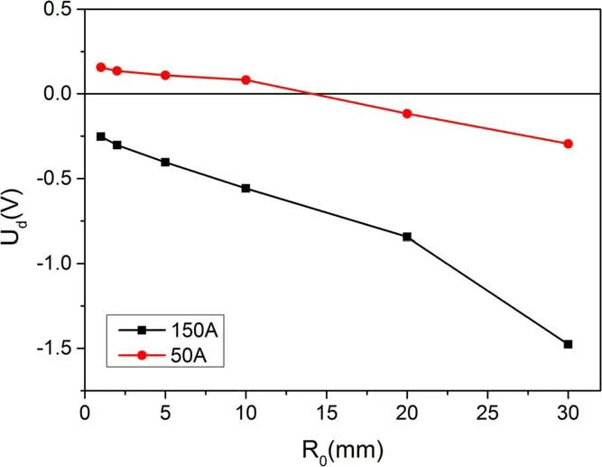
Figure 14.The voltage drop of anode sheath as a function of the anodic root radius.
Finally, the current-voltage characteristics predicted by our model are displayed in figure 15 (note that the experimental values [37] correspond to the diffused cathode root).Uacis the arc column voltage predicted by our model,Ush,cis the voltage drop of the cathode sheath predicted by the model andUsh,ais the voltage drop of the anode sheath predicted by the model.The total arc voltagepredicted by our model includes the arc column voltageUac, the voltage drop of the cathode sheathUsh,c, and the voltage drop of the anode sheathUsh,a.It can be observed that the voltage drop of the arc columnUacrises with the increase of current, while the voltage drop of the cathode sheath and anode sheath decreases with the increase of current.The total arc voltage droppredicted by our model correlates highly with themeasured by the experiment.

Figure 15.Current-voltage characteristics.
4.Conclusions
A self-consistent numerical model of the whole argon arc discharge region that included electrodes was developed in this work.The arc column was a 2D model containing the ionization and thermal non-equilibrium,which was combined with a 1D electrode sheath model.The influence of the plasma species diffusion near the electrode region is investigated using Maxwell-Stefan equations and generalized Ohm’s law.A self-consistent model was then established to elucidate the whole physical arc discharge process.The gap between the cathode and anode is 10 mm.The simulation results showed that:
(a) In the arc core region, the plasma was obviously in the state of thermal equilibrium and ionization equilibrium,while the plasma deviated from thermal equilibrium and ionization equilibrium in the arc fringe region.
(b) The actual electron density decreased rapidly in the region close to the anode and cathode due to nonequilibrium ionization, which resulted in a large gradient of electron numbers in these regions.Consequently, electron diffusion played an important role in the near-cathode and near-anode regions.
(c) When the anode arc root gradually contracted, it was easy to obtain a positive voltage drop of the anode sheath(I = 50 A),while it remained difficult to acquire a positive voltage drop (I = 150 A).
(d) The total arc voltage drop predicted by our model was in good agreement with the experimental values.
The results show that the characteristics of the near cathode and near anode regions can be predicted successfully by our global coupling model.In future work, a more complete chemical non-equilibrium model is needed to self-consistently calculate the contracted anode arc roots.
Acknowledgments
The work is supported by National Natural Science Foundation of China (Nos.11875256, 12005023, 11705202), Scientific Research Fund Project of Anhui Jianzhu University(No.2020QDZ09) and Anhui Provincial Natural Science Foundation (No.1808085MA12).
ORCID iDs
猜你喜欢
语数外学习·高中版上旬(2020年10期)2020-09-10
美与时代·美术学刊(2020年3期)2020-06-29
妇女生活(2017年9期)2017-09-13
故事林(2016年11期)2016-06-08
 Plasma Science and Technology2022年5期
- Plasma Science and Technology的其它文章
- Synthesis of Ag-decorated vertical graphene nanosheets and their electrocatalytic efficiencies
- Upgrade of an integrated Langmuir probe system on the closed divertor target plates in the HL-2A tokamak
- Numerical study of atmospheric-pressure argon plasma jet propagating into ambient nitrogen
- Effects of O2 addition on the plasma uniformity and reactivity of Ar DBD excited by ns pulsed and AC power supplies
- Design and first result of combined Langmuir-magnetic probe on J-TEXT tokamak
- Selective catalytic reduction of NOx with NH3 assisted by non-thermal plasma over CeMnZrOx@TiO2 core-shell catalyst