
Dynamic characteristics of multi-arc thermal plasma in four types of electrode configurations
2022-06-01 07:56YanjunZHAO赵彦君GuohuaNI倪国华WeiLIU刘卫HongmeiSUN孙红梅SiyuanSUI隋思源DongdongLI李冬冬HuanZHENG郑瓛ZhongyangMA马中洋andChiZHANG张弛
Plasma Science and Technology 2022年5期
Yanjun ZHAO (赵彦君), Guohua NI (倪国华), Wei LIU (刘卫),Hongmei SUN (孙红梅),Siyuan SUI (隋思源), Dongdong LI (李冬冬),Huan ZHENG (郑瓛),2, Zhongyang MA (马中洋) and Chi ZHANG (张弛)
1 Institute of Plasma Physics, Chinese Academy of Sciences, Hefei 230031, People’s Republic of China
2 University of Science and Technology of China, Hefei 230026, People’s Republic of China
3 Anhui Province Key Laboratory of Medical Physics and Technology,Hefei 230031,People’s Republic of China
Abstract The enhanced volume of thermal plasma is produced by a multi-arc thermal plasma generator with three pairs of discharge electrodes driven by three directed current power suppliers.Combined with a high-speed camera and an oscilloscope,which acquire optical and electric signals synchronously,the dynamic behavior of different kinds of multi-arc discharge adjusted by the electrode arrangement is investigated.Also, the spatial distributions and instability of the arc discharge are analyzed in four electrode configurations using the gray value statistical method.It is found that the cathodic arcs mainly show a contracting state,while the anodic arcs have a trend of transition from shrinkage to a diffusion-like state with the increase of the discharge current.As a result of the adjustment of the electrode configuration, a high temperature region formed in the center of the discharge region in configurations of adjacent electrodes with opposite flow distribution and opposite electrodes with swirl flow distribution due to severe fluctuation of arcs.The discharge voltage rises with increased discharge current in this novel multi-arc plasma generator.It is also found that anode ablation mainly occurs on the conical surface at the copper electrode tip, while cathode erosion mainly occurs on the surface of the inserted tungsten and the nearby copper.
Keywords: multi-arc, electrode configuration, dynamic character, erosion
1.Introduction
Arc plasma has achieved great improvement in theoretical research and industrial applications in the last 50 years[1-3].Because of its excellent characteristics of high temperature,high enthalpy, suitability for extensive working pressure and diverse discharge gas species, thermal arc plasma has been widely used in thermal spray[4,5],material processing[6,7],waste treatment[8],etc.Arc plasma usually displays a shrink discharge shape whose radial dimension is millimeters of magnitude due to the self-induced magnetic compression and the thermal pinch effect, and there is a large gradient of the distribution on temperature and the pressure.This reduces the mixing efficiency of particles with plasma, and limits the application of plasma in powder treatment(i.e.thermal spray,spheroidization,etc)[9,10].To make better use of arc plasma in these fields, it is important to enlarge its volume.
Many researchers have performed numerous studies on how to generate large-volume arc plasma.Initial attempts were made to generate three arcs by sharing three cathodes with one anode to increase the volume of arc plasma and obtain better treatment of particles [9, 11].The method of increasing the volume of arc plasma with multiple arcs was further developed in later studies.Wang et al[12,13]developed a six-cathode arc plasma device,which could generate large-volume diffused arc plasma.To maintain this diffused arc plasma, a working gas with low enthalpy,low conductivity and high thermal conductivity may be a requirement.Through the introduction of multi-phase power supply technology, three-phase alternating current (AC) arc discharge was successfully carried out by Rehmet et al[14,15],and its dynamic discharge characteristics were investigated.In their research, the arc is formed between the two electrodes with the maximum line voltage and discharged alternately between two of three electrodes as the electrode potential changes.To reduce the discharge instability produced by intermittent discharge and obtain arc plasma with larger volume, Watanabe [16-18] et al designed a 12-phase AC power supply to produce a multi-phase AC arc with twelve thoriated tungsten electrodes.By studying the dynamic characteristics and temperature distribution of arcs in a clockwise discharge pattern and flip-flop pattern, the understanding of multi-arc plasma generation technology and its industrial application to particle vitrification were enhanced.
Although some valuable results have been achieved in previous studies of multi-arc plasma, the understanding of multi-arc plasma needs to be further improved.In this work,a novel multi-arc plasma generator with three pairs of electrodes driven by three direct current (DC) power supplies is developed.Based on the idea of using more than one arc to expand the size of the arc plasma, this approach can be applied to large-scale industrial applications due to mature DC power supply technology.Also,its characteristics in four types of electrode configurations are investigated using the methods of high-speed camera and synchronous voltage acquisition technology.By adjusting the configuration, the generation of a large-volume arc plasma can be realized,and the spatial distribution of plasma can be adjusted to meet the requirements of different industrial application scenarios.
2.Experimental setup
The experimental setup is illustrated schematically in figure 1.It is mainly composed of one multi-arc plasma generator, a power and gas supply unit, and a diagnostic system.The multi-arc plasma generator consists of a cylindrical chamber of 150 mm in diameter and six identical electrode assemblies inserted into the chamber with uniform circumferential distribution.The setup of all six electrode assemblies is the same,with a rod-shaped water-cooled stainless-steel electrode and a coaxial shrinking quartz tube of 20 mm in outlet inner diameter.The electrode of 16 mm in diameter is equipped with a tapered copper tungsten insert at the front with a cone angle of 80°and a diameter of 7 mm on the electrode tip.An insulated swirl gas distribution ring is placed between the electrode and the quartz tube in the vicinity of the outlet to produce vortex gas.The six electrode assemblies are divided into three pairs according to the cathode and anode connections, corresponding to three DC power supplies.In the present work, argon is chosen as the discharged gas with a gas flow rate of 2 cubic meters per hour for each electrode.
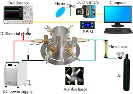
Figure 1.The experimental and diagnostic setup of multi-arc thermal plasma.
The voltage generated by arc discharge is obtained by differential voltage probes (Keysight, N2790A) connected to the cathode and anode of the same power supply, respectively.Three differential voltage probes are connected to the oscilloscope (Agilent, DSO-X 4024A) to save the voltage signals.A high-speed camera (Hsvision, Eosens Mini-2) is placed behind the optical assembly to collect arc discharge pictures at 2000 frames per second (fps) and 300 μs of exposure time.The primary optical devices include one neutral filter with 10 percent of transmittance and one band-pass filter whose central wavelength is 760 nm with a full width at half maximum of 10 nm.The high-speed camera and oscilloscope are triggered synchronously by the rising edge signal given by the pulse-width modulation(PWM) signal generator.
In this work, the characterization of multi-arc discharge in four kinds of electrode configurations is investigated.As illustrated in figure 2,the top four pictures are experimental images of the electrode arrays, corresponding to the structural illustrations below.The labels 1A, 2A, 3A and 1C, 2C, 3C represent three anodes and cathodes of the multi-arc generator, respectively,in which the Arabic number indicates three corresponding connected power supplies.The cathode and anode assemblies are interlaced around the circumference of the chamber marked as one circle with a solid black line,as shown in figure 2.All of the electrode tips point towards the center of the chamber and any two adjacent electrodes are connected to the same power supply, in which this electrode configuration is named as adjacent electrodes with opposite flow distribution (AEOF), as illustrated in figure 2(a).To investigate the discharge behavior on a swirling flow field in the multi-arc generator, the structure with swirl flow distribution is designed with central axis extension lines of the six electrodes that form an inscribed circle with a radius of 5 mm (figure 2(b)), called adjacent electrodes with swirl flow distribution (AESF).Taking electrical characteristics into consideration,the cathode and anode linked with the same power source are placed in opposite positions, as shown in figures 2(c) and (d).According to the above description of the flow field distribution,the electrode configurations of opposite electrodes with opposite flow distribution (OEOF),illustrated in figure 2(c),and opposite electrodes with swirl flow distribution (OESF), shown in figure 2(d), are designed.The default distance between two opposite electrodes is set as 45 mm in this paper,and the circle of the dotted blue line in the figure is located in this 45 mm diameter area.The difference in labels in the experimental and schematic images is caused by the arrangement of optical elements, and the electrode configurations of the discharge images discussed later in this paper all correspond to schematics rather than experimental diagrams.
3.Results and discussion
3.1.Typical arc discharge images in the multi-arc generator
To get a clear view of the discharge characteristics of our multiarc plasma, the combination of a high-speed camera and oscilloscope was introduced to investigate the dynamic behavior of the multi-arc images in four different types of electrode configurations.As shown in figure 3,the typical discharge images in four electrode configurations with the discharge current ranging from 100 A to 250 A are presented from left to right.The discharge area is marked by the solid yellow circle with a diameter of approximately 50 mm that contains the region surrounded by six electrodes and small parts of the six electrode tips.The Arabic numeral in the upper right corner of the image is the corresponding moment of discharge image capture,in milliseconds(ms).To remove the artificial consciousness,discharge images of 0 ms were selected for further illustration in figure 3.Because of the special arc shape produced by this multi-arc plasma generator,the three arcs were divided into three cathodic arcs and three anodic arcs according to the electrode connection.It can be clearly seen that the arcs’intensities were all enhanced with the increase of the discharge current (especially in the arc current increase from 100 A to 200 A) in the four electrode configurations.With the increase in the current,the ability of the cathode to emit electrons increases, which enhances the degree of gas ionization.Conversely, the self-induced magnetic compression of the arc becomes stronger with the increasing current, which limits the further increase in the radial dimension of the arc.
Moreover, the arcs were too weak to extend into the center of the discharge region at 100 A of discharge current,and each arc moved along the edge of the discharge area.With the increase in current,the arcs had a tendency to move towards the central region due to the following reasons.The radial dimension of the arc decreased near the cathode,which increased the arc pressure in the vicinity of the cathode, and further produced a pressure gradient towards the arc column.The plasma flowed from the vicinity of the cathode to the arc column, while the cold gas near the cathode being pumped into the cathodic arc formed a Maecker effect [19, 20].As a result of the Maecker effect in the vicinity of the electrodes,especially the cathodes,the plasma velocity increased rapidly with the increase in current due to more cold gas being pumped into the discharge region.In addition, the cathodic arc(or anodic arc)was repelled more strongly by the adjacent anodic arc (or cathodic arc) under the Lorentz force and tended more towards the central area with the increase in current.As seen in figure 3, the cathodic arcs were always constricted, regardless of the change in discharge current or electrode configuration.However, the brightness of the anodic arc decreased and there was no significant constricted attachment in the vicinity of the anodic arc root at higher discharge current.The arc in this diffusion-like state can be obviously seen in the anodic arc of 2A with the OESF configuration at 250 A for example.The anodic arcs transformed from constriction to diffusion when the discharge current increased,and the diffused anodic arcs appeared more clearly in electrode configurations with the swirl flow field.Further details are discussed in the following section.

Figure 3.Typical discharge images in the multi-arc generator of electrode configurations in (a) AEOF, (b) AESF, (c) OEOF and (d) OESF with the discharge current varying from 100 A to 250 A.
3.2.Spatial-temporal evolution of arcs
Figure 4 presents the detailed dynamic discharge images with 0.5 ms interval and the three arc voltages under the conditions of an arc current of 200 A in the multi-arc generator with the AEOF configuration.The voltage of arc one was the potential difference between 1A and 1C, and the same labeled method applied to arcs two and three.In the time range, as shown in figure 4, three arcs formed a discharge circuit with their own power supply, while the tails of the arcs converged in the center of the discharge area.Due to the heating of the arcs and the transport of ionized gas, a bright ionized region was generated in the center of the discharge area,which is labeled by the yellow dotted circle shown at 0.5, 1, 1.5, 3 ms, etc, as shown in figure 4(a).Further,the arcs extended to the central ionization region to form the connection with other arcs.It can be seen from the discharge images that three arcs converged together at 0 ms.Besides, arc one and arc three connected at 2 ms and 2.5 ms.Moreover, arc one and arc two connected together at 5 ms and 7 ms.In the arc connection process, the arc-to-arc restrike between the anodic arc and cathodic arc occurred, i.e.in the discharge images at 4.5 ms for arc three.The anodic arc was divided into two parts: one was the arc that existed at the last moment and the other was newly created.In the discharge images at the next moment of 5 ms,the newly generated anodic arc became strong while the old one disappeared.The similar arc-to-arc restrike phenomena appeared in the anodic arc of arc two at 7.5 ms.In the discharge images, the three cathodic arcs were obviously luminous and constricted, and the anodic arcs of 2A and 3A were mostly diffused.The diffusion-like anodic arc mainly came from the rapid swing of the anodic arc.The anode erosion enhanced the movement of the anodic arc root,which further improved the swing of the anodic arc.In addition,the evaporation of metal vapors in the vicinity of the anode electrode as a result of the erosion increased the degree of ionization near the electrode, which also enhanced the swing of the anodic arc.Furthermore, this kind of swing of the anodic arc made it more likely to be a diffuse state.More details of erosions and arc root movements will be discussed in the following section.
It is well known that the arc voltage is proportional to arc length in conventional DC plasma torches.However, in this novel multi-arc generator, the arc lengths of three arcs were difficult to extract as a result of their connections with each other and the dimension loss generated by the optical projection.Even so,some correlation could be found between arc length and voltage variation.For example, the length of arc two elongated,while its voltage increased from the discharge time of 2 ms to 2.5 ms.During 10 ms of discharge time,shown in figure 4(b), the vibration of arc one was slight,resulting in less fluctuation of voltage.The high frequency burr signal shown on the voltage waveform was caused by the breakdown of arc-to-arc,which was discussed in our previous work [21].

Figure 4.Detailed dynamic discharge images (a) with the voltages (b) of three arcs collected synchronously in the multi-arc generator in AEOF at 200 A.
As a kind of electromagnetic fluid,the dynamic character of the arc was highly influenced by the distribution of the gas flow field.The instantaneous discharge images with the synchronous voltages in the multi-arc generator with the AESF configuration are illustrated in figure 5, at an arc current of 200 A.In this configuration, the anodic arcs were mainly in the diffusion-like state, and the cathodic arcs were in the constricted state.It was found that the fluctuation of discharge images and voltages mainly occurred on arc three,while arc one and arc two were more stable.The restrike between the cathodic arc and the anodic arc of arc three, as well as the extension to the center of the discharge area, was consistent with the change in voltage signal descending and ascending.An ionized region in the central discharge area labeled by the yellow dotted circle presented an obvious anticlockwise swirling flow at moments of 0, 1, 2.5 ms, etc,shown in figure 5(a).This central ionizing region was mainly affected by the tails of the cathodic arcs because the energy of shrinking cathodic arcs was more concentrated,which caused the cathodic arcs to be subjected to a stronger arc jet force to dominate the central discharge.Due to the mutual repulsion between the three arcs in the central region,each arc would be forced to contract towards the electrode.Thus, the cathodic arc was slightly offset towards its adjacent anode, which formed the discharge loop with it.This was so that the flow direction of the three cathodic arcs was counterclockwise in this electrode arrangement, which further caused the counterclockwise vortex of the center ionization region.Because this vortex was deeply influenced by the arc shape and flow field, once the arc shape changed (such as the arc shrunk towards the electrode) or the flow field in the discharge area fluctuated,the vortex was likely to vary and even disappear in the next moment, which resulted in the vortex no longer persisting.Due to the high temperature of the arcs,the central ionized region processing high temperature was suitable for melting refractory particles with a high melting point.

Figure 5.Detailed dynamic discharge images (a) with the voltages (b) of three arcs collected synchronously in the multi-arc generator in AESF at 200 A.
In a previous study[21],the three arcs formed a complete discharge loop with the three driving power sources instead of three separate loops between arcs with their own power sources.It was clearly found that the anodic arcs linked with their nearby cathodic arcs in the multi-arc generator in the OEOF at 200 A, as shown in figure 6(a) in the present work.Here, 3A connected with 1C, 2A concatenated to 3C, while 1A linked with 2C with a time range of 10 ms.It was worth noting that the arc discharge was relatively stable in our experiment, which was due to the equilibrium between the Lorentz force and gas drag force on the arcs.Under relative equilibrium conditions, the anodic arcs and the cathodic arcs showed a relatively stable state of contraction,and there were almost no large-scale variations on the arcs.Also,a relatively low ionized cavity was formed in the center of the discharge region, labeled by the yellow dotted circle, because the arcs could not extend to the center under the force on the arcs.

Figure 6.Detailed dynamic discharge images (a) with the voltages (b) of three arcs collected synchronously in the multi-arc generator in OEOF at 200 A.
The arc discharge exhibited significant instability when the swirl structure was applied to the opposite electrode arrangement,as shown in figure 7.Such a small change in the electrode arrangement affected the force equilibrium state constructed between the three arcs, which made the lap between the cathodic arc and the anodic arc disordered.An anodic arc would quickly switch connections between its right and left cathodic arcs, as in the anodic arc of 1A shown at 3.5 ms and 4 ms, which caused large fluctuations in the arc voltage.After 2 ms, the anodic arc of 1A reconnected to the originally connected cathodic arc of 3C.The fluctuation of the flow field greatly increased the uncertainty of the connection between the arcs.However,the cathodic arcs still maintained a relatively stable discharge state and showed a significant shrinkage state.In contrast, under the influence of huge fluctuation, the anodic arcs presented a diffusion-like state.Moreover,the intense interaction between the arcs intensified the ionization in the central discharge region and formed a bright region with a higher temperature in the central region,as presented at 0.5, 1, 3.5 ms, etc.The arcs became distorted in this highly fluctuating environment, resulting in a higher discharge voltage.

Figure 7.Detailed dynamic discharge images (a) with the voltages (b) of three arcs collected synchronously in the multi-arc generator in OESF at 200 A.
3.3.Spatial distribution and fluctuation of arcs
To investigate the spatial distribution and fluctuation of arcs in different configurations, the gray values of 1000 discharge images collected continuously were calculated using the average value and standard deviation [22] and the results are shown in figure 8.The averaged gray value was obtained using the following formulawhereIijis the gray value of the image at each pixel, and f and N are the frame number and total number of frames,respectively.Also,the formulawas used to calculate the standard deviation of the arc images.From the spatial distribution of the arcs in the multi-arc generator with different electrode configurations illustrated in figure 8(I),the cathodic arcs were easily identified due to their constricted stable discharge state.However, there were no significant resolutions in the gray distribution of anodic arcs because of the existence of a diffusion-like state.Furthermore,it can be seen in the standard deviation of the discharge images in figure 8(II) that the fluctuation near the cathodic arcs was slight but the instability around the anodic arcs was strong.The strong instability of the anodic arcs was due to the shift of anodic arc roots and the swing of anodic arcs.The huge fluctuation of arcs enhanced the heat conduction from thermal arcs to the weak ionized gas in the central area, and a high temperature region formed in the center of the discharge region, as obviously presented in AEOF and OESF.The fluctuation was slight in OEOF,as shown above,as a result of its stable discharge process.

Figure 8.The average distributions (I) and standard deviations (II) of arc discharge images in the multi-arc generator of electrode configurations in (a) AEOF, (b) AESF, (c) OEOF and (d) OESF at 200 A.
3.4.Volt-ampere characteristics of arcs
The volt-ampere characteristics of arc discharges are an important result used to investigate the electrical characteristics of arcs.Figure 9 shows the variation of the average arc voltage as a function of the arc current under four electrode arrangements.Except for the OEOF type,the discharge voltage generally increased with the increasing current.The increase in the arc voltage mainly depended on the increase in the arc length.However,the arc length could not be accurately measured due to multiple overlapping of electric arcs and arcs extending out to the electrode plane.It was found that the arcs tended towards the central discharge region with the increase in current, and the interaction between arcs became stronger, thus intensifying the arc extension out of the electrode plane.Therefore, it was possible for the arc length to increase with the current within an appropriate range.As the current increased further, the enhanced Lorentz force between the arcs inhibited the arc stretching effect more significantly, which limited the further increase in the arc length.In addition, the augmentation of the current made the arcs more inclined towards the central discharge area, thus increasing the heat conduction and convection between the arcs and the cooling gas.Therefore, the system needed to provide more energy to maintain the arc discharge state.These positive resistance properties were also found in [23-25].The Lorentz force between the arcs and the drag force of the gas reached a relative balance in the OEOF pattern, which resulted in hardly any change in arc length with the increasing current.Therefore, the arc voltage varied slightly with different currents in the OEOF pattern.

Figure 9.Arc voltages on the multi-arc generator of electrode configurations in (a) AEOF, (b) AESF, (c) OEOF and (d) OESF.
3.5.Electrode erosion and anodic arc root movement
Electrode erosion seriously affects the stability of arc discharge and the working life of an arc generator.Photographs of electrode ablation in such a multi-arc generator are shown in figure 10.In the picture, the photographs of anodes and cathodes after discharge about one hour under the same working conditions showed that the anode erosion was more serious than that of the cathode.Moreover, it was found that the cathode ablation mainly occurred on the surface of the inserted tungsten and the nearby copper cover.As the electron-emitting electrode, the surface of the tungsten revealed poor flatness due to the attachment of the cathodic arc roots.The erosion of the copper cover near the tungsten was due to the strong electric field distribution, which led to the breakdown of the arcs.As an electron-emitting electrode, the cathode ablated weakly, further making a stable discharge of cathodic arcs with the combination of the Maecker effect.The anode erosion resulted in rapid movement of the anodic arc root on the anode surface.Furthermore,the alternating change of the cathodic arc connected with the anodic arc caused the anodic arc root to move reciprocally along the conical surface of the electrode tip.Therefore, the anode ablation mainly occurred on the surface of the copper cone at the electrode tip.To better illustrate the movement of the anodic arc root,the arc images with the anodic arc shrinking in OEOF at 150 A,which were easy to observe,are presented in figure 11.Taking 3A as an example to illustrate this, there was an arcto-arc restrike and large-scale shift of the anodic arc root in the picture.For illustrative purposes, the edge of electrode of 3A is marked with a red line with the letters a and b identifying two reverse directions.From the discharge image at 7 ms to the next moment at 7.5 ms, the new arc channel between 3A and 1C was built due to the newly formed anodic arc near the side labelled b in red font.Then, the new anodic arc slid towards 2C, while the arc root moved from b to a.After a while,the arc-to-arc restrike occurred between 3A and 1C at 9 ms.The displacement of pixels corresponding to the center point of the anodic arc root was calculated to quantify the movement velocity of the arc roots.The velocity of the arc root of 3A varied from 1 m s−1to 7 m s−1in the pictures shown below.The rapid movement of the anodic arc roots increased the swing of the anodic arcs, which enhanced the diffusion-like state of the anodic arcs.

Figure 10.Photographs of anode(top)and cathode(bottom)erosion.
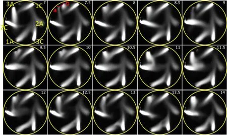
Figure 11.The movement of anodic arcs in the multi-arc generator in OEOF at 150 A.
4.Conclusions
In conclusion, the discharge characteristics of one novel multi-arc plasma generator in four types of electrode configurations were investigated using the synchronous acquisition of discharge images and voltage signals.The dynamic evolution images, spatial distribution and fluctuation of arc discharges under typical parameters of four configurations are analyzed and compared, respectively.The results show that the instabilities of arc discharge in the multi-arc generator in AEOF and OESF are more intensive than those of the other two configurations at the discharge current of 200 A, and the average discharge voltage and fluctuation in the OEOF configuration are the lowest due to the balance of forces, and a high temperature region formed in the center of the discharge area,as obviously presented in AEOF and OESF.In addition,the cathodic arcs still maintain a shrinking state, while the anodic arcs change from a shrinking state to a diffusion-like state with the increasing current, which is the result of anode ablation and the electromagnetic force.Moreover,an uptrend of the voltage is found with the rising discharge current,which is different from the negative resistance characteristics of those in a traditional DC torch.The analysis of the movement behavior of the anodic arc root shows that the arc roots mainly shift along the conical surface of the copper electrode front with a velocity of several meters per second.The different spatial distributions of the arc discharge are achieved through the regulation of the electrode configuration, which provides better solutions in industrial application of multi-arc plasma.
Acknowledgments
This work was supported by National Natural Science Foundation of China (No.11875295), and the National Key R&D Program of China (No.2019YFC0119000).
猜你喜欢
江苏教育研究(2022年8期)2022-04-27
上海工艺美术(2021年4期)2021-04-24
科技研究·理论版(2021年20期)2021-04-20
阅读(快乐英语高年级)(2019年8期)2019-09-10
创新作文(1-2年级)(2019年3期)2019-09-03
民生周刊(2019年16期)2019-08-22
小溪流(画刊)(2018年10期)2018-03-18
校园英语·中旬(2016年8期)2016-07-09
小学教学研究·新小读者(2016年6期)2016-06-22
短小说(2004年8期)2004-09-06
 Plasma Science and Technology2022年5期
- Plasma Science and Technology的其它文章
- Synthesis of Ag-decorated vertical graphene nanosheets and their electrocatalytic efficiencies
- Upgrade of an integrated Langmuir probe system on the closed divertor target plates in the HL-2A tokamak
- Numerical study of atmospheric-pressure argon plasma jet propagating into ambient nitrogen
- Effects of O2 addition on the plasma uniformity and reactivity of Ar DBD excited by ns pulsed and AC power supplies
- Design and first result of combined Langmuir-magnetic probe on J-TEXT tokamak
- Selective catalytic reduction of NOx with NH3 assisted by non-thermal plasma over CeMnZrOx@TiO2 core-shell catalyst