
Variational Solution of Coral Reef Stability Due to Horizontal Wave Loading
2022-06-14 04:04ZHANGQiyiLONGQuanandLIXiaowu
ZHANG Qiyi, LONG Quan, and LI Xiaowu
Variational Solution of Coral Reef Stability Due to Horizontal Wave Loading
ZHANG Qiyi1), 2), *, LONG Quan1), 2), and LI Xiaowu1), 2)
1) Department of Ocean Engineering, College of Engineering, Ocean University of China, Qingdao 266100, China 2) Key Laboratory of Ocean Engineering of Shandong Province, Ocean University of China, Qingdao 266100, China
This paper proposes a theoretical method that can be used in calculating the stability of coral reefs or artificial islands. In this work, we employ the variational limiting equilibrium procedure to theoretically determine the slope stability of coral reefs covered with hard reef shells as a result of horizontal wave loads. A reasonable functional is proposed and its extremum is calculated based on the conservation of energy. Then, we deduce the stability factorNof coral reefs under combined vertical self-gravity and horizontal wave loads, which is consistent with the published results. We compare some classic examples of homogeneous slopes without hard shells in order to analyze the accuracy of results generated by this variational procedure. The variational results are accurate and reliable according to the results of a series of detailed calculations and comparisons. Simultaneously, some other influence parameters on the reef stability, including the top-layer tensile strength of coral reef, the amplitude of wave loading, and the tensile crack, are calculated and discussed in detail. The analysis results reveal that the existence of a hard reef shell could enhance the stability of reef slope and that there is a nonlinear relationship between the stability factorN, the shear strength, and the thicknessDof the covered coral reef shell. Furthermore, the emergence of top-layer tensile cracks on the coral reefs reduces their stability, and the action of horizontal wave loads greatly decreases the stability of coral reefs. Thus, the hard shell strength and its thickness D, surface tensile crack, and wave loading require more careful attention in the field of practical engineering.
coral reef stability; tensile crack; variational solution; horizontal wave loading
1 Introduction
Coral reefs are representative components of marine geomorphology, are widely distributed in the deep sea and shallow waters, and especially exist in warm waters onboth sides of the equator (Putnam., 2017). In particular, coral reef topography is widely distributed in Taiwan Island, the South China Sea, and Australian waters (Pirazzoli, 1993; Harris, 2004; Beaman, 2008;Woodroffe and Webster, 2014). In recent years, with the rapid expansion of marine resources and the ongoing construction of civil structures and military facilities on coral reefs, there is an urgent need to carefully study the stability of coral reef slopes. The regularity of horizontal distribution of coral reefs tends to form steep seaward slopes, hard reef flats and coral sand lagoons covered with hard reef shells depending on the hydrodynamic environment and geological conditions, as well as the long-term formation process of coral reefs in the South China Sea (Rogers, 2017). In this special marine environment and geological condition, a typical two-layer profile appears on the vertical cross-section, with incompact coral sand to a depth of 10–20m consisting of coral debris, gravel, and coarse sand; and a deep layer of hard coral reef with good integrity (Gong., 2012; Kordi and O’Leary, 2016). A typical profile of the geomorphic features of coralreef in the South China Sea is shown in Fig.1 (Zhang, 2017), wherein the coral reef is covered with a hard shell at the surface. As shown in Fig.1, the geological structure of the coral reef consists of the following parts:1) the upper seaward slope; 2) the outer reef flat; 3) the reef margin; 4) the inner reef flat; 5) the lagoon slope; 6) the lagoon basin. The first four parts (1–4) are strongly subjected to hydrodynamic action.
Such projects as the construction of ports and military structures, along with shipping and tourism activities, tend to destroy the hard shell of coral reefs, which may significantly reduce their general stability; in turn, this can reduce the stability of structures established on the reefs (Chen, 2017). Therefore, the integrity of the reef shellhas a great influence on ensuring the stability of coral reefs. In order to investigate theoretically the influence of horizontal wave loads on the stability of coral reefs, and in light of energy conservation considerations, we propose an energy functional for coral reef stability resulting from the combined vertical self-gravity and horizontal wave loads. Then, we obtain a variational solution for the stability of coral reefs covered with a hard shell under horizontal wave loading, thereby demonstrating the influence of the horizontal wave loads and the original reef shell on the reef slope stability. We simplified the geomorphic features of the coral reef in order to reduce the difficulty of theoretical derivation and mathematical calculation, as shown in Fig.2. Table 1 presents data on the hydrodynamic and geological conditions related to the coral reef, obtained from the actual monitoring of the sea area and the coral reefs.
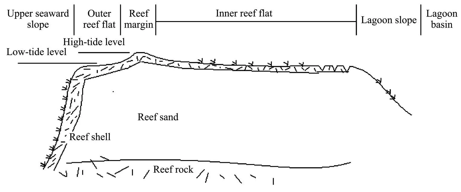
Fig.1 Typical coral reef profile.

Fig.2 Simplified model of a coral reef covered with hard shell.
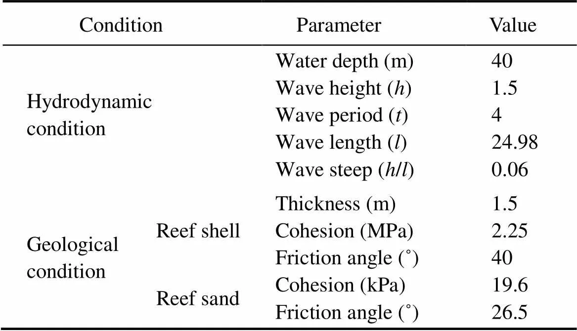
Table 1 Water depth and wave condition in front of the coral reef
According to a previous study, the variational limiting equilibrium (LE) solutions are identical to the upper plastic limit analysis solutions; thus, the top hard shell can obviously improve reef stability; however, this study ignored the horizontal action due to the wave loads (Zhang., 2018). The main advantage of this variational approach is that it is free from any artificial kinematical or static admissible assumptions, which is the case for many existing methods mentioned in the literature. In order to assess the stability of coral reefs under horizontal wave loading, the concept of safety factor is adopted in the current paper, which is usually defined as the ratio of the total shear strength available on the slip surface to the total shear strength required for equilibriums.
2 Variational Analyses
Here, we theoretically derive the stability factor of the coral reef using the variational LE in order to determine the reef stability covered with hard reef shells and undergoing the horizontal wave loads. The analysis process is as follows.
2.1 Mathematical Formulation of the Basic Problem
A typical reef slopeinclined in the horizontal direction is shown in Fig.3. The coral reef profile is identified by the unit weight, cohesion, and internal friction angle. Here,is an assumed height of coral reef described in this paper. The horizontal wave load(), the vertical load on top of the reef(), and the tension crackon the reef roof are introduced, assuming that the collapse of the coral reef is due to the combined vertical self-gravity load and horizontal wave loads. The LE method is based on the following equations:
1) Satisfaction of the plastic yielding criterion=()along the shear slip surface(). We adopt the Mohr-Coulomb’s failure condition as:

where=()and=()are the distributions of the tangential and normal stress along the assumed slip surface(), respectively, andDrefers to the thickness of the surface reef shell. To facilitate easy calculation in this paper, we set=tan().
3) Here, the horizontal wave load() is applied on the coral reef, and the wave shape adopted before wave breakage is calculated as in Fig.4. Considering the complexity of wave force calculation theory on slope, and in order to simplify the theoretical derivation of horizontal wave pressure, it is assumed that the reef shell is inclined at a fixed angleto the horizontal plane; besides, the surface roughness of the reef shell and the wave reflection effect are ignored.
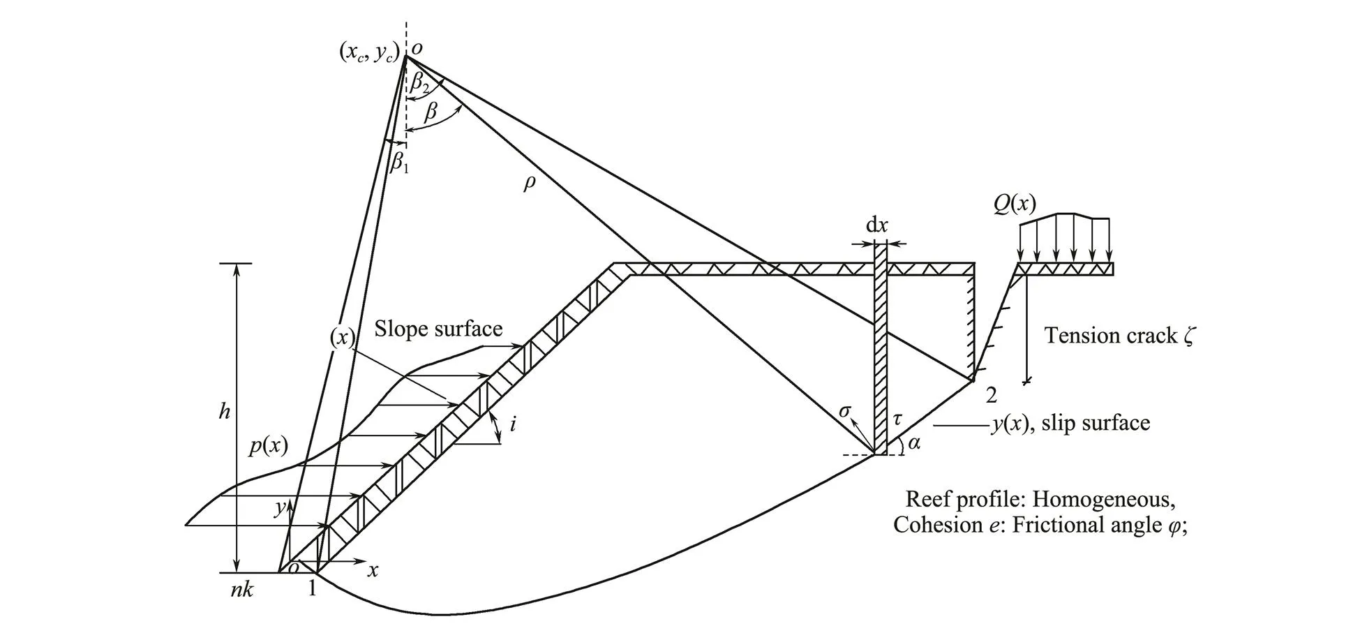
Fig.3 Basic geometric parameters and definitions.
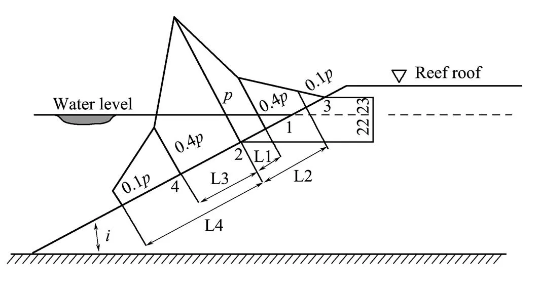
Fig.4 Calculation of wave pressure p(x).
The wave pressure(kPa) acting on the coral reef is calculated as follows:

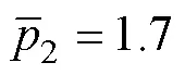
where1=1.35 and

The vertical coordinates2and3of point 2 and point 3 are respectively determined by the following equations:
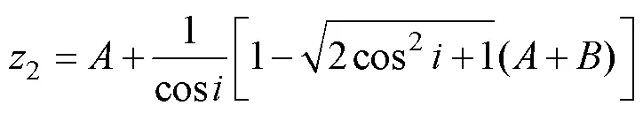

whereandare the formula parameters, which can be found in the Soviet architecture standard.
Based on the coral reef mass being in a state of LE, as shown in Fig.3, the equilibrium equations of horizontal and vertical forces and the moment are respectively satisfied as follows (Zhang, 2008):
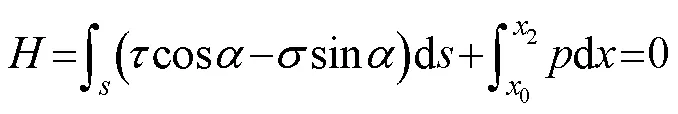
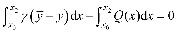

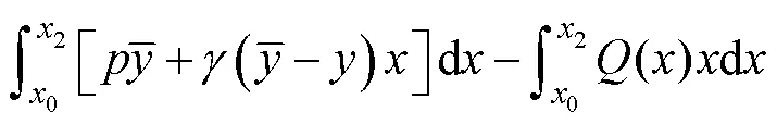
whereis the arc length along the shear sliding surface(), andis the slope inclination of(). Eqs. (3a) and (3b) are the horizontal and vertical force equilibrium equations in the two-dimensional (2D) plane strain state, respectively, and Eq. (3c) is the moment equilibrium equation of the rigid-plastic sliding coral reef. We then introduce Mohr-Coulomb’s failure criteria into the above equations and combine the geometrical relations along the continuous boundaries shown in Fig.3, cos=d/d; sin=d/d. Under these simplifications, we can obtain the following equilibrium equations which can indicate the overall stability equations of this layered slope:


2.2 Safety Factor and Critical Height of Reef Slope
To quantify the margin of reef safety relative to an LE state under combined horizontal and vertical loads, we replace the real shear strength parameters of coral reefs with an artificially reduced factor. This is also known as safety factor and is expressed as:
The critical heighthof the coral reef under combined vertical and horizontal wave loads, for which we can obtain the reef stability when it reaches a state of LE, is decided by the normal stress functions and kinematical shape() and() along the shear sliding surface, respectively. Thus, the reduced factorand slope heightcan be described as a variational functional of the mentioned shape and stress functions. Consequently, the safety factorFand the critical heighthare respectively considered the extreme values, as follows:


wherey() andσ() are the shear sliding surface and normal stress distribution along the optimal failure slip surface, respectively.
In the process of solving the functional extremum shownin Eq. (6), we set the safety factorFto 1 and use the critical heighthto estimate the stability of the coral reef. Thus, the LE issue can be stated as solving two sets of mathematical functions() and(), which can obtain the extreme valuehof the functional and simultaneously satisfy the coral reef equilibrium equations (Eq. (4)) mentioned above.
We can transform the basic equilibrium issues into the standard isoperimetric problem of the variational method using the derivation process previously introduced by Baker (1981, 2003). We select the force equilibrium equation in the vertical direction as the integral object, using the horizontal force and moment equilibrium equation as the integral constraints. The parameters1and2are Lagrange’s undetermined multipliers, respectively, which are constants in the process of variational derivation. Then, by introducing the two integral constraints (Eqs. (4a) and (4c), respectively), we can obtain the following expression[(),()] given by


We have to obtain the optimal sliding surface and its corresponding normal stress distribution in order to solve the extremum of the above auxiliary functional shown in Eq. (7b).
2.3 Functional Variational Solution
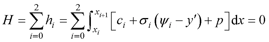
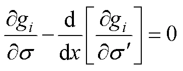
In order to solve the safety factorFand critical heighthof the coral reef, the mentioned functional must satisfy the Euler partial differential equations,, the necessary conditions for the existence of an extreme, namely,

According to Baker and Garber (1977, 1978), we can derive the family of the potential shear sliding surface by solving the first Euler partial differential equation, whereas the second Euler equation could yield the normal stress acting along the shear sliding surface. In this paper, the shear slip surface equation and the normal stress equation are derived easily by solving the Euler partial differential equations (Eqs. (8a) and (8b)), which could be expressed as Eqs. (9a) and (9b). The derivation process is consistent with that followed by Baker. The final theoretical formulas of the slip surface and its corresponding normal stress are as follows:
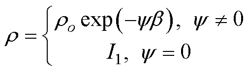

whereρ, Ω,1, and2are the integration constants. Note that Eqs. (9a) and (9b) are formulations of the family of the potential sliding surface and its corresponding normal stress in a polar coordinate system, respectively. We utilized the following coordinate transformation, which can convert the coordinate values from polar to rectangular coordinates:


where (,) is the polar coordinate system with a center (x,y), as shown in Fig.3.
Next, we can integrate the force and moment equilibrium equation explicitly once the form of the potential sliding surface and its corresponding normal stress distribution are obtained. The final form of this equilibrium equation is described as
(11)
It is important to note that we must still consider the constraints listed below in order to obtain a specific theoretical solution of the above Euler partial differential equation.
1) Geometrical boundary conditions
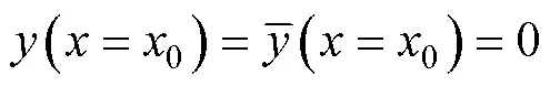
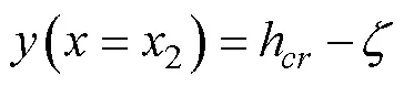
Note that the two endpoints, 0 and 2, of the sliding surface are not fixed,, they are separately variable along the slope surface. The tensile crack depthcan be obtained using the tensile strength of the coral reef. The longitudinal coordinates are already given.
2) Transversality condition among layers
In the process of searching for the optimal sliding surface, the coordinates of the two endpoints, 0 and 2, cannot ascertain which are related to the loading and the geological properties, so it is necessary to apply the transversality conditions among the layers, whose general form is given below:
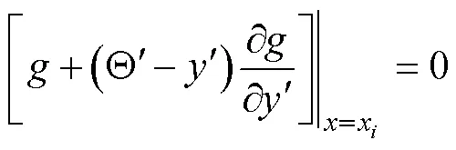
wherexmay be either0,1, and2. The Θis a particular curve passing through the two endpoints. By substituting relevant expressions into Eq. (14), utilizing the coordinate transformations in Eq. (10), and then making a detailed calculation, the following expression is obtained:

By applying the above Eq. (15) to the endpoint 0, we obtain the following expression:

where the parametercindicates the cohesion of the coral reef shell.


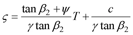
On the other hand, if the ultimate tensile strengthof the hard reef roof is known, we can obtain the depth of tension crack, as follows:
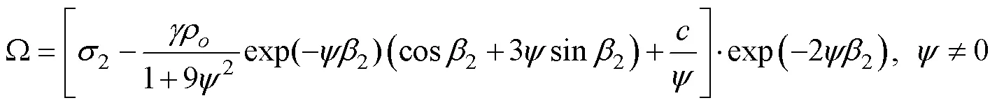
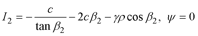
3) Stress boundary condition
Let us substitute the stress boundary condition2=(=2) into Eq. (9). In doing so, we can solve the integral constants Ω and2, after which the following expressions are obtained as shown in Eq. (18):
Hence, we can statically determine the basic variational problem by simultaneously solving the equilibrium equations as well as the geometrical boundary, stress boundary, and transversality conditions. The following two calculation results, which consider different slope inclinations and reef tensile strengths shown in Fig.5, give the typical shear sliding surfaces and their corresponding normal stress distributions with slope angles π/4 and π/2, respectively.
2.4 Numerical Verification of Theoretical Solutions
As shown in Fig.5, the general finite element software Plaxis is used to simulate the engineering example. This is done in order to verify the rationality of the variational results derived theoretically in this paper and to check the shape of the sliding surface and the normal stress distribution law along the sliding surface. The numerical calculation results are shown below.
The shear sliding surfaces shown in Figs.6(a) and (c) indicate that the hard surface shell constrains the shallow sliding of the coral reef and increases the general stability of the coral reef. The safety factorNof the coral reef withfour differential potential critical sliding surfaces is shownin Fig.6(a), which indicates that the sliding surface gradually transits from shallow failure to deep failure, increases from 16.6 to 28.6. In addition, Fig.6(c) shows that the safety factor increases from 4.16 to 10.3. Furthermore, the failure modes shown in Figs.6(b) and (d) indicate that the appearance of tensile cracks at the top surface of the coral reef accelerates the appearance of shear sliding surface and reduces the general stability of the coral reef. Furthermore, the failure modes of the numerical calculation are consistent with those of the variational solution derived in this paper. Therefore, protecting the integrity of the coral reef shell is very important in ensuring the overall stability of the coral reef.

Fig.5 Typical slip surfaces and normal stress distributions of variational solutions.
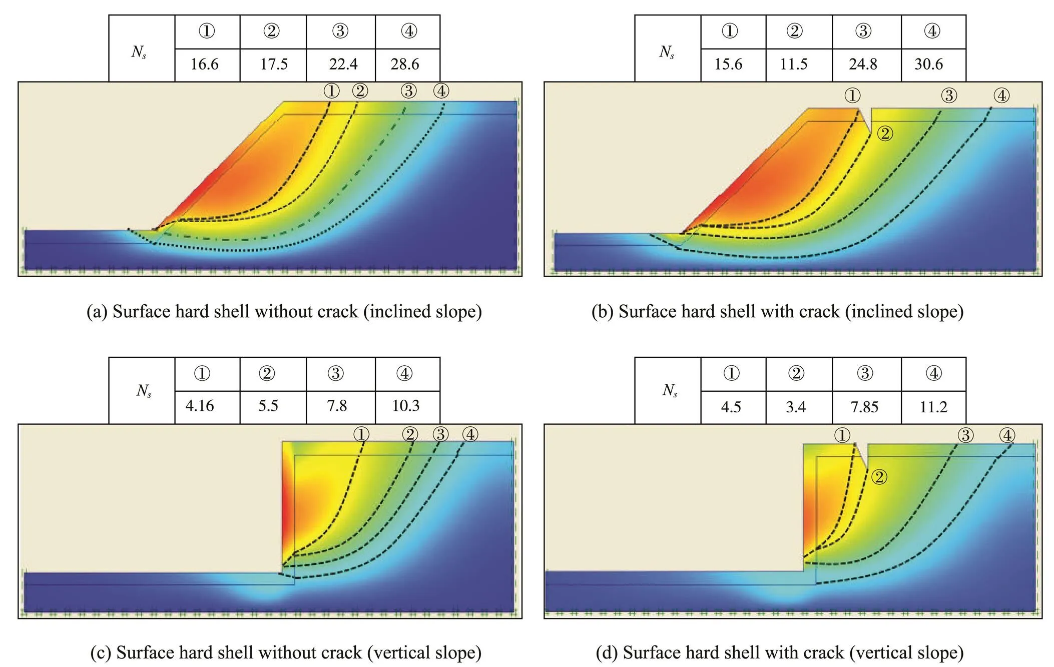
Fig.6 Numerical results of coral reef failure modes.
3 Comparison and Discussion of Results
3.1 Variational Solution of the Stability FactorNs
Actually, it is difficult to obtain the analytical results of the nonlinear simultaneous equations derived theoretically in this paper. For this reason, a trial-and-error process is utilized to generate the numerical solutions. To facilitate easier calculation, we express all the quantities in their non-dimensional forms. For example, the length-type parameters take the expression of=/, and the stress-type parameters are expressed as=/. Furthermore, we use a non-dimensional parameter, which has been defined as N=h/by Taylor (1948). By doing so, we obtained some theoretical results indicating the critical safety factors for various conditions with the different slope inclinations as well as the internal friction angle of the coral reef, as illustrated in Fig.7. By comparison, we find that the safety factor derived using the variational LE procedure is similar to that obtained by the upper bound analysis method.
Fig.7 shows that the safety factorNis a function ofand(internal friction angle and reef inclination, respectively) for the case of no reef shell covered. Comparing the results with the upper bound analysis results published by Chen (1975), we can expect the variational approach to obtain the exact theoretical values ofN, and to derive a set of theoretical calculation fourmulas.
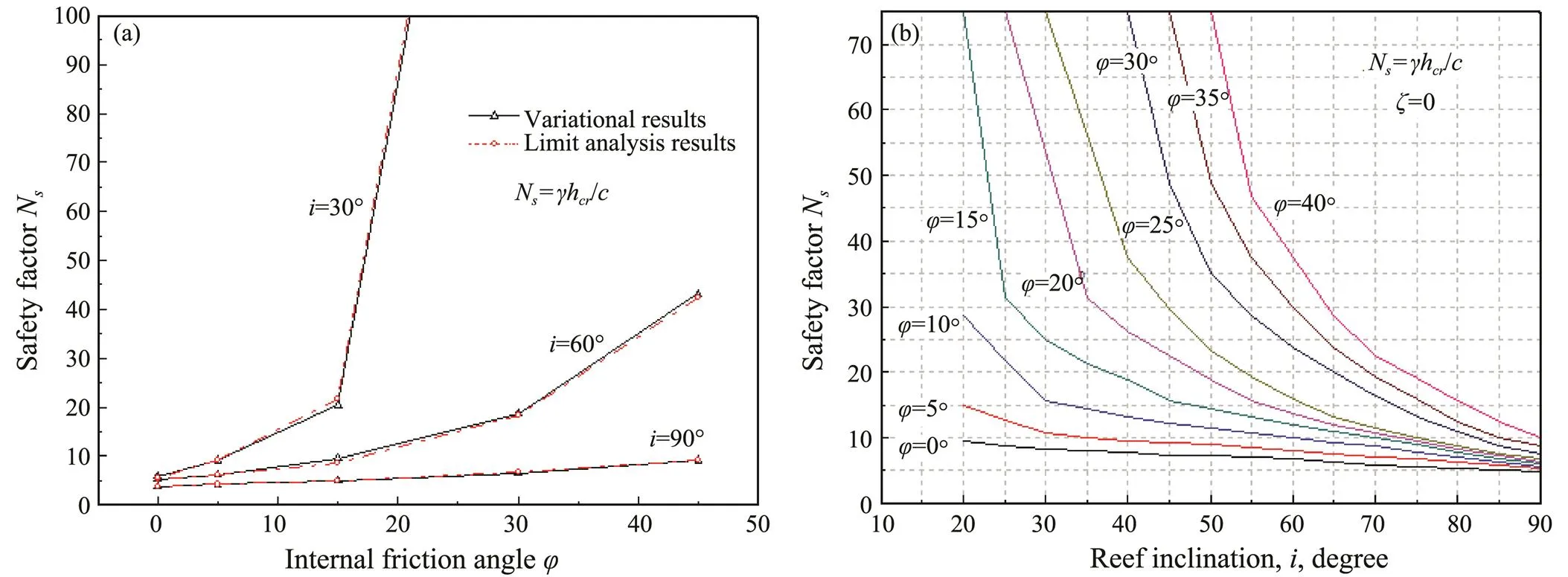
Fig.7 Safety factor without reef shell. (a), effect of internal friction angle on Ns; (b), effect of reef inclination on Ns.
3.2 Safety Factor with Hard Reef Shell
Some investigators have concluded that the influence of shell thicknessDon the coral reef stability (, to cover the surface of a coral reef) is not negligible. Fig.8 presentsNas a function of internal friction angleand reef inclinationfor the case of a coral reef with a hard shell (D). On the one hand, the dotted lines in Fig.8 represent the reef safety factor without the reef shell being covered. On the other hand, the straight lines mean that with a hard reef shell, the existence of a continuous covered reef shell significantly increases the stability of the coral reef.
3.3 Safety Factor with Tensile Crack
Fig.9 shows the effect of surface tensile strengthon the safety factorNwith the emergence of the tensile crack. We can see that there exists a linear growth relationship between the safety factorNand the tensile strength. Furthermore, the figure shows that the safety factorNof the coral reef is approximately linearly related to the surface tensile strength, and the line slopes are basically the same under different reef inclination angles. 3.4 Safety Factor Due to Horizontal Wave Loads
Two sets of typical wave data (Figs.10 and 11), which include water depth in front of the coral reef 40m, wave period 4s, wave length 24.98m, and wave heights 1 and 5m, respectively. The wave loads() acting on the reef are solved, and the safety factorNof coral reefs is analyzed under wave loads and self-gravity. Based on the variational calculation results, we determine that the safety factorNof the coral reef decreases with the increase of wave load.
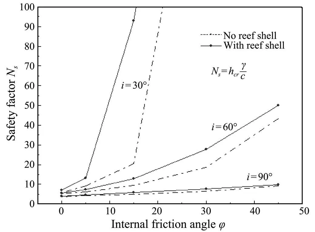
Fig.8 Safety factor with hard shell covered.

Fig.9 Safety factor with tensile crack ζ.(a), internal friction angle φ=5˚; (b), internal friction angle φ=20˚.
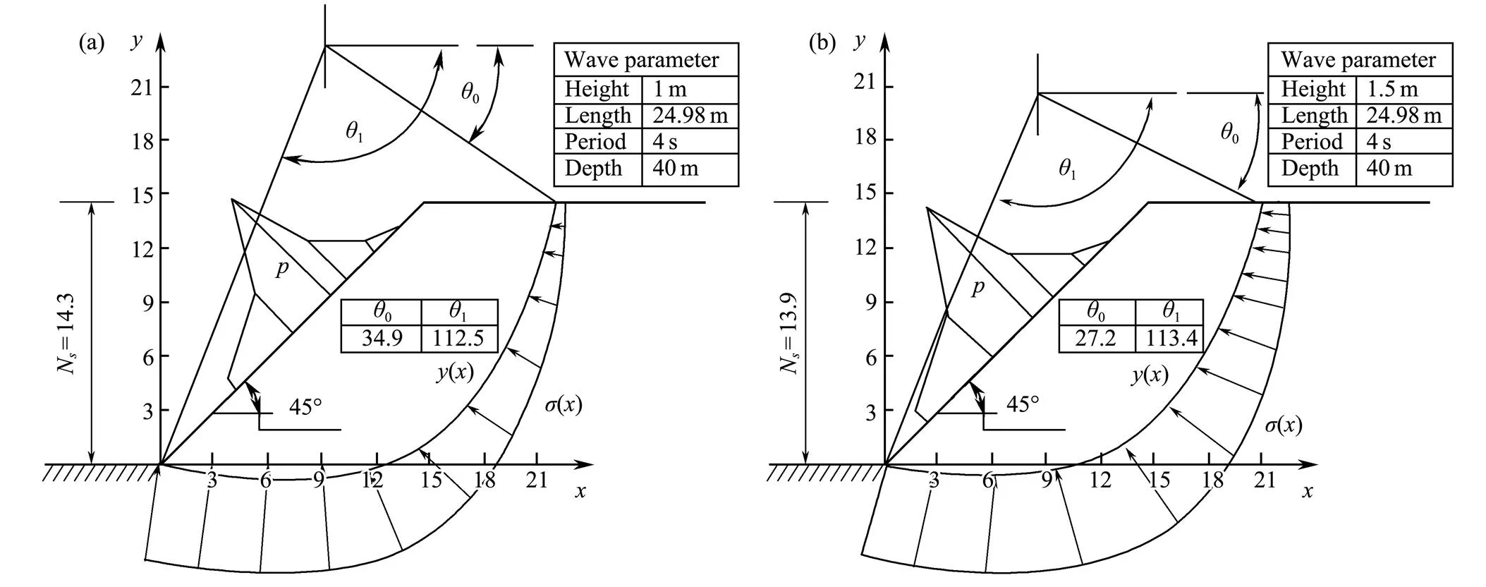
Fig.10 Safety factor with an inclination angle of 45˚. (a), wave height, 1m; (b), wave height, 1.5m.
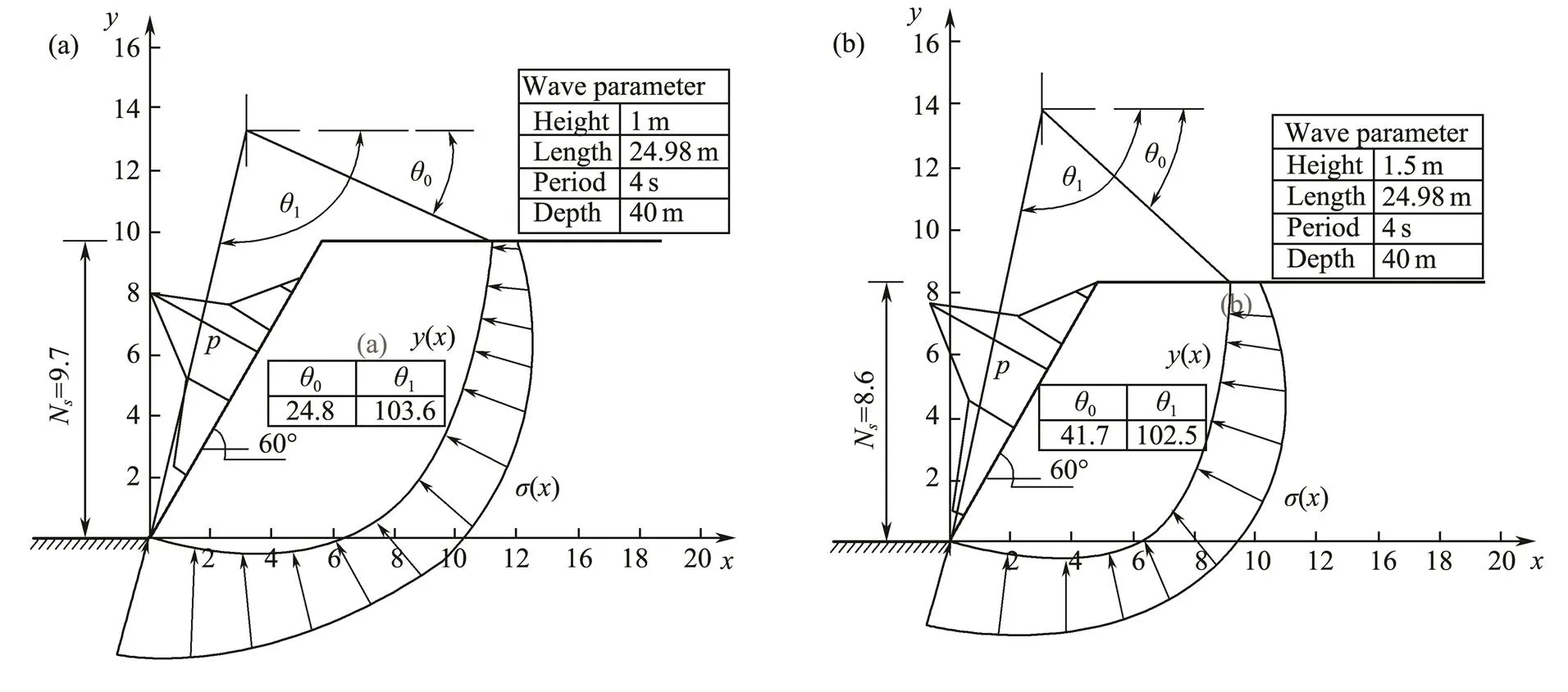
Fig.11 Safety factor with an inclination angle of 60˚. (a), wave height, 1m; (b), wave height, 1.5m.
4 Conclusions
In this paper, the variational LE procedure is applied to obtain the safety factorNof the coral reefs covered with hard reef shells and to withstand wave loads in the horizontal direction. Some meaningful conclusions are drawn as follows:
1) The analysis results show that the continuous hard shell covering the coral reef enhances the stability of the coral reef. Furthermore, there is a nonlinear relationship between the safety factorNand the tensile strengthand the thicknessDof the surface reef shell.
2) The horizontal wave loads weaken the safety factorNof the coral reef, and the existence of tensile crackfurther reduces the safety factorNof the coral reef.
Acknowledgements
This paper is supported by the Project of National Science and Technology Ministry (No. 2014BAB16B03), andthe National Natural Science Foundation of China (No. 51679224).
Baker, R., 1981. Tensile strength, tension cracks, and stability of slopes., 21 (2): 1-17.
Baker, R., 2003. Sufficient conditions for existence of physically significant solutions in limiting equilibrium slope stability analysis., 40: 3717-3735.
Baker, R., and Garber, M., 1977. Variational approach to slope stability.. Tokyo, Japan, 2: 9-12.
Baker, R., and Garber, M., 1978. Theoretical analysis of the stability of slopes., 28 (4): 395-411.
Beaman, R. J., Webster, J. M., and Wust, R. A. J., 2008. New evidence for drowned shelf edge reefs in the Great Barrier Reef, Australia., 247: 17-34.
Chen, C. S., Xia, Y. Y., and Bowa, V. M., 2017. Slope stability analysis by polar slice method in rotational failure mechanism., 81: 188-194.
Chen, W. F., 1975.. Elsevier, Amsterdam, 851pp.
Gong, E. P., Zhang, Y. L., Guan, C. Q., and Chen, X. H., 2012. The Carboniferous reefs in China., 1 (1): 27-42.
Harris, P. T., Heap, A. D., Wassenberg, T., and Passlow, V., 2004. Submerged coral reefs in the Gulf of Carpentaria, Australia., 207: 185-191.
Kordi, M. N., and O’Leary, M., 2016. Geomorphic classification of coral reefs in the north western Australian shelf., 7: 100-110.
Pirazzoli, P. A., Arnold, M., Giresse, P., Hsieh, M. L., and Liew, P. M., 1993. Marine deposits of late glacial times exposed by tectonic uplift on the east coast of Taiwan., 110: 1-6.
Putnam,H. M., Barott, K. L., Ainsworth, T. D., and Gates, R. D., 2017. The vulnerability and resilience of reef-building corals., 27 (11): 528-540.
Rogers, J. S., Monismith, S. G., Fringer, O. B., Koweek, D. A., and Dunbar, R. B., 2017. A coupled wave-hydrodynamic model of an atoll with high friction: Mechanisms for flow, connectivity, and ecological implications., 110: 66-82.
Taylor, D. W., 1948.. Wiley, New York, 714pp.
Woodroffe, C. D., and Webster, J. M., 2014. Coral reefs and sea-level change., 352: 248-267.
Zhang, Q. Y., Liu, Z. J., Dong, X. S., and Wu, L. P., 2018. Theoretical analysis of coral reef stability in South Sea., 17 (5): 1026-1032.
Zhang, Q. Y., Luan, M. T., Yuan, F. F., and Jin, D., 2008. Bearing capacity of rectangular footings on inhomogeneous foundation under combined loading., 30: 970-975.
Zhang, Q. Y., Shi, H. D., Gao, W., and Li, J. F., 2017. Non-hydrostatic numerical simulation of wave propagation deformation on coral reef terrain., 36: 1-9.
(Oceanic and Coastal Sea Research)
https://doi.org/10.1007/s11802-022-4846-0
ISSN 1672-5182, 2022 21 (3): 647-655
(November 21, 2020;
February 28, 2021;
March 16, 2021)
© Ocean University of China, Science Press and Springer-Verlag GmbH Germany 2022
Corresponding author. E-mail: zhangqiyi@163.com
(Edited by Xie Jun)
 Journal of Ocean University of China2022年3期
- Journal of Ocean University of China的其它文章
- Effect of Intertidal Elevation at Tsuyazaki Cove, Fukuoka,Japan on Survival Rate of Horseshoe Crab Tachypleus tridentatusEggs
- Asian Horseshoe Crab Bycatch in Intertidal Zones of the Northern Beibu Gulf: Suggestions for Conservation Management
- Experimental Investigation on the Interactions Between Dam-Break Flow and a Floating Box
- High Microplastic Contamination in Juvenile Tri-Spine Horseshoe Crabs: A Baseline Study of Nursery Habitats in Northern Beibu Gulf, China
- Influence of Autonomous Sailboat Dual-Wing Sail Interaction on Lift Coefficients
- Nonlinear Dynamic Analysis and Fatigue Study of Steep Wave Risers Under Irregular Loads