
Shaking Table Tests and Seismic Response of Three-Bucket Jacket Foundations for Offshore Wind Turbines
2022-06-14 05:00DINGHongyanPANChenZHANGPuyang1WANGLeandXUYunlong
DING Hongyan, PAN Chen, ZHANG Puyang1), , *, WANG Le, and XU Yunlong
Shaking Table Tests and Seismic Response of Three-Bucket Jacket Foundations for Offshore Wind Turbines
DING Hongyan1), 2), 3), PAN Chen3), ZHANG Puyang1), 3), *, WANG Le3), and XU Yunlong3)
1),,300072,2),,,300072,3),,300072,
The seismic response characteristics of three-bucket jacket foundations for offshore wind turbines (OWTs) and the li- quefaction of the surrounding soil are particularly important for the development and application of this type of structure for offshore use. Using the shaking table test and three-dimensional finite element analysis, different magnitudes of simulated earthquake waves were used as inputs to the shaking table to model seismic excitations. The resulting changes in the excess pore water pressure and acceleration response of the soil under horizontal earthquake are compared in this paper. Calculations of the anti-liquefaction shear stress and equivalent shearing stress during the earthquake, determination of the areas prone to liquefaction, and identification of the effect of the three-bucket jacket foundation on the soil liquefaction resistance were conducted by developing a soil-structure finite element model. The development law of the soil’s amplification effect on seismic acceleration and the seismic response of the foundation soil under various magnitude earthquake waves were also discussed. Results indicate that liquefying the soil inside the bucket of the foundation is more difficult than that outside the bucket during the excitation of seismic waves due to the large upper load and the restraint of the surrounding hoop. This finding confirms the advantages of the three-bucket jacket foundations in improving the liquefaction resistance of the soil inside the bucket. However, the confinement has a barely noticeable impact on the nearby soil outside the skirt. The phenomenon of soil liquefaction at the bottom of the skirt occurred earlier than that in other positions during the seismic excitation, and the excess pore water pressure slowly dissipated. The acceleration amplification coefficient of the sand outside the bucket increases with depth, but that of the sand inside the bucket is substantially inhibited in the height range of the bucket foundation. This result proves the inhibition effects of the three-bucket jacket foundations on the seismic responses of soils. The li- quefied soil layer has a significant effect in absorbing a certain amount of seismic wave energy and reducing the amplification effect. The numerical simulation results are consistent with the phenomenon and data measured during the shaking table test. The current study also verifies the feasibility of the excess pore water pressure ratio and the anti-liquefaction shear stress method for judging soil liquefaction.
three-bucket jacket foundation; seismic response; shaking table test; liquefaction analysis
1 Introduction
As the supporting structure of offshore wind turbines (OWTs), some new innovative foundations offer easy in- stallation, convenient towing of the assembly, and high load capacity (Li., 2014; Ding., 2015, 2020; Ren., 2022; Wang., 2022). Bucket foundations have additional advantages of dispersing the load and improving the anti-moment capability; thus, research into their application has received increasing amounts of attention from the marine engineering community (Li., 2015; Wang., 2019a; Fu., 2020). Many studies confirm the feasibility and economy of the jacket structure using a mul- ti-bucket foundation. Suction bucket jackets were success- fully installed in China in 2020 (as shown in Fig.1).
The marine geological environment is relatively complex. OWT foundations not only need to resist loads from wind, waves, currents, and superstructures but may also beaffected by marine earthquakes. The foundations for OWTsare mostly located in offshore zones where the ocean floor comprises saturated sand and silt, which can liquefy during marine earthquakes. Thus, the bearing capacity of a li- quefied area would be substantially reduced or even totally incapacitated, seriously affecting the service life and inte- grity of infrastructure. The seismic response characteristics of the three-bucket jacket foundation for OWTs and the liquefaction analysis of the surrounding soils are particularly important for the use of foundation structures and their reliability.
The use of the three-bucket jacket foundations is new; thus, previous work on the seismic response of this type of foundation structure is limited. However, numerous dis- cussions on the seismic performance of these bucket foun- dations using Finite element (FE) methods or shaking table tests are available and have obtained useful conclusions and results. Ju and Huang (2019) developed an analytical framework for the NWEL 5 MW jacket-type OWT and sub- jected it to seismic, wind, and wave loads using the FE me- thod with the structure-soil interaction (SSI). They found that almost all loadings of the members are induced by the seismic loads for an earthquake with a peak acceleration larger than 0.52g. This paper also indicated that a first- mode tuned mass damper can efficiently reduce the responsepeaks. Alati(2015) investigated the seismic responseof tripod jacket foundations using fully coupled non-lineartime-domain simulations. Their results indicated that earth- quake loading may cause a significant increase in the resulting structural stresses. Seong(2017) used centrifuge experimental modeling and the FE method to evaluate the natural frequencies of OWTs. Huo(2018) dis- cussed the seismic response of OWTs with the occurrence of long-period ground motions considering SSI. Asheghabadi(2019) used the three-dimensional FE method to investigate the seismic response of suction bucket foundations. Their results were in good agreement with their centrifuge results. Their simulation also indicated that the sandy soil outside the caisson is prone to liquefaction due to its limited confinement. Emdadifard(2010) and Prowell (2011) conducted shaking table tests to simulate dynamic structural responses and compared their results with the data from a FE study, which demonstrated consistent results. Karimi and Dashti (2016) developed a fully- coupled 3D nonlinear numerical model and compared their results with those from their centrifuge experiments for a shallow-coupled structure on liquefiable sand. These studies guide the evaluation of seismic soil-foundation-structure interactions on the ground that can liquefy.

Fig.1 Multi-bucket jacket foundations for OWTs in China.
Liquefaction can cause a wide range of structural damages due to the resulting loss of load-bearing capacity; thus, considering liquefaction in structural tests and analyses is necessary. Ku and Chien (2016) investigated the behavior of wind turbine jacket foundations subjected to seismicloading and found that the pore pressure generation modelcan be used to simulate soil liquefaction. Zhang. (2007) performed a series of centrifuge tests on suction foundations for OWTs under static and cyclic loadings to investigate dynamic responses. They found out that the liquefaction of the soil is likely to occur in shallow sandy lay-ers. Zhang. (2014) developed a structural design for alarge-scale bucket foundation for OWTs with seismic loads and found that their foundation exhibited good resistance to soil liquefaction during earthquakes by improving the anti-liquefaction capability of the soil inside and under the foundation because of the overburden pressure of the self- weight and the constraint effect of the skirt. Ding. (2007) studied the determination of liquefaction for bucket foundations of OWTs under ice-reduced vibration based on the anti-liquefaction shear stress method. They also ana- lyzed the liquefying areas near the bucket foundation due to earthquakes using the FE software ADINA. Wang. (2020) conducted a series of centrifuge shake table tests to investigate the seismic response and liquefaction characteristics of hybrid monopile foundations and concluded that the soil maintains part of its strength and stiffness during shaking due to the high stress confinement under this type of foundation.
The above studies provide useful insights into the seismic responses and liquefaction resistance characteristics of bucket foundations. Therefore, shaking table tests and three-dimensional FEA were applied for the work describ- ed in this paper. Different magnitudes of simulated seismic waves were used as seismic excitation model inputs to the shaking table to induce the changes in excess pore water pressure and acceleration response of the soil under horizontal earthquakes. Calculations of the anti-liquefac- tion shear stress and equivalent shearing stress during the earthquake, determination of the areas prone to liquefaction, and the development law of the amplification effect of soil on seismic acceleration were conducted by deve- loping a soil-structure FE model. The effects of the three- bucket jacket foundation on the soil liquefaction resistance and the seismic response of the foundation soil were then extracted from the resulting data.
2 Experimental Design of the Shaking Table Test
2.1 Dimensional Similarity for Shaking Table Tests
The dynamic dimensional similarity law derived from theBuckingham π dimensional analysis theorem has been wide- ly used in the related design of experiments for shaking table model tests of SSI in liquefaction sites.
The dynamic model and the prototype are in the gravity field of 1, that is, the gravitational acceleration similarity ratioS=1. Therefore, the similarity parameters of elastic modulus, density, acceleration, and length should satisfy the following equations:
The full counterweight method reveals that when the material of the model is the same as the prototype, that is, the elastic similarity ratioS=1, then=1. Therefore, ap- propriate counterweights should be required on the model structure to compensate for the lack of gravity and inertia effects according to the premise of retaining the overall ri- gidity of the model structure.
The partial counterweight method was applied consider- ing the actual bearing capacity of the shaking table. Three controllable scaling factors during the shaking table test are set asS=1/50000,S=1/100,S=1. Thus, the stress similarity ratioS/21/5. The elastic similarity ra- tioS=1/5, which is difficult to achieve based on rea- listic conditions. The current study aims to investigate the influence of three-bucket jacket foundations on the liquefaction of saturated sand and verify the rationality of shaking table tests and the three-dimensional FE method. The study also focuses on the development of seismic liquefaction phenomena and characteristic indicators. Therefore, the similarity ratio error between the model and the prototype does not affect the main purpose of this study. The 403 stainless steel was used as the material of the model. The similitude law and coefficients of the other main physical quantities are shown in Table 1.
Table 1 Parameters of example toroidal drive system
2.2 Experimental Model Equipment and Design
The mass similarity theory indicates that the weight of the three-bucket jacket foundation model was 6.61kg when composed of 403 stainless steel and the mass of the selected prototype model was 901016.94kg. The weight of the counterbalance should satisfy=SM−M(whereMis the mass of the prototype, andMis the mass of the model). That is, the weight should be 11.41kg. The mass and natural frequency must meet the dynamic similitude law. Therefore, the principle of weight distribution is based on the need for the center of gravity of the model to be as close as possible to that of the prototype. Thus, the total mass of the counterbalance was 11kg, which was distri- buted among the top of the bucket with a mass of 1.122kg, the jacket with a mass of 1.62kg, and the tower with a mass of 7.26kg.
The three-bucket jacket foundation model was processed on the basis of the dynamic similitude law. The subscale model comprises three buckets, each with a diameter of 159 mm and a height of 120mm. The jacket connection was welded using a 12.7mm diameter stainless steel pipe, thus demonstrating an overall height of 0.5m. The upper tower comprised a 30mm diameter stainless steel tube with a height of 0.6m. The stainless steel counterweight components were also welded in their positions, as shown in Fig.2.
These shaking table tests were performed in the Engineering Structure and Disaster Prevention and Mitigation Laboratory of Shandong Jianzhu University. The parameters of the shaking table are listed in Table 2.
The laminar shear box used in the shaking table test cansuccessfully simulate the soil boundary, ideally weaken the seismic reflections and the seismic wave scattering effects, and reproduce the shear deformation characteristics of soil (Zhang., 2014). The box can be regarded as a free field beyond three times the diameter of the model from its center throughout the boundary effect range of the shak- ing table test and the model’s scale. Therefore, the laminar shear box was chosen as 2210mm×1510mm×1670 mm. The box comprised aluminum alloy lined with a fle- xible rubber layer in the interior to prevent soil and water seepage, absorb seismic waves, and reduce boundary effects. Moreover, the superior elasticity of the rubber layer played a positive role in improving the restoring capabi- lity of the shear box. Each layer of the frame was welded together by two 2050mm×75mm×5mm and two 1550mm×75mm×5mm rectangular steel plates connected by steel cables. The space between the frames was 15mm. Balls that can rotate arbitrarily in the steel ring on a diameter of 190mm and swing back and forth by 90mm according to geometric calculations were also placed on the top of the column. The laminar shear box is depicted in Fig.3.

Fig.2 Test model. (a), design concept sketch; (b), entity graph.

Table 2 Main parameters of shaking table

Fig.3 Container for laminar shear soil tests. (a), design con- cept sketch; (b), entity graph.
The rigid base of the laminar shear box was fixed onto the shaking table using high-strength bolts threaded on both ends and nuts. The box was positioned after the assembly such that the center of mass of the box coincided with the center of the table, as shown in Fig.4.
Fig.4 Diagrams of the hole arrangement on the shearing table and the laminar shear soil container position.
2.3 Test Soil
The test soil is fine sand named ‘Fujian standard sand’ with a soil layer thickness of 0.95m. The physical properties of the standard sand are shown in Table 3, and the grain size distribution curve is shown in Fig.5. The Fujian standard sand has a relatively small particle size, and this characteristic is preferable in centrifuge modeling becausethe scale effect is minimized (Randolph., 1992; Wang., 2019b). The sand can maintain the proper internal friction angle for the bearing capacity analysis despite its small particle size. Therefore, the law of gravitational si- milarity of the soil was neglected for this test. The layeringmethod was used to prepare the sand by using a flat mouthsander for the sand distribution after airing and sifting. The layering thickness was 50mm to ensure adequately uniform soil. The preparation method of the test soil is illustrated in Fig.6.
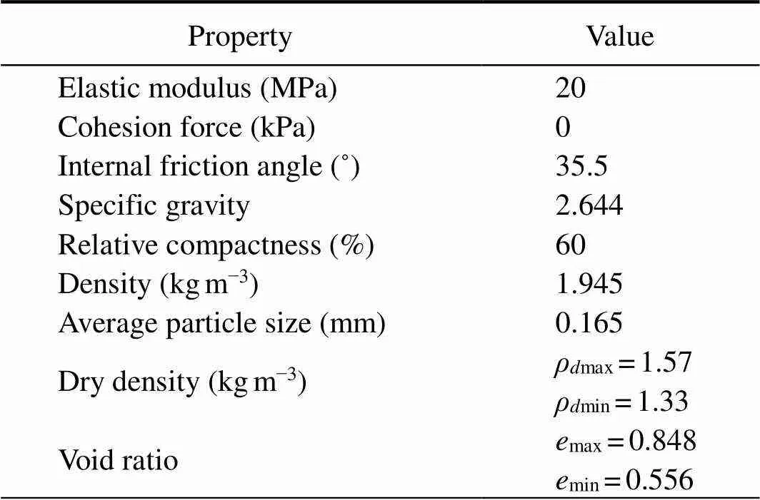
Table 3 Properties of the standard sand used

Fig.5 Grain size distribution of the standard sand.
2.4 Loading System
The typical seismic waves (EI-Centro waves) were used in this test as the longitudinal (-direction) input excitations to the shaking table. The peak acceleration was adjusted in accordance with the acceleration similarity coefficient as an input corresponding to increasing earthquake intensities. That is, they followed the sequence from 1 to 5: 0.035, 0.1, 0.175, 0.22, and 0.4. White noise was used for a frequency sweep test before each waveform adjustment. The time history curves of the input and output white noise were compared, as shown in Fig.7. The high degree of coincidence between the two curves indicated the good output performance of the shaking table. The loading of the next working conditions could be performed until the load- ing completion of the working conditions for each previous process and the dissipation of pore water pressure. The seismic waves are depicted in Fig.7 (taking an acceleration peak value as 0.1for an example), and the loadingconditions are shown in Table 4.
2.5 Sensor Arrangement
The pore water pressure sensors (K is used for identifi- cation, with a diameter of 8mm and a height of 10mm) and the single-track acceleration sensors (A is used for iden- tification, with an area of 10mm×6mm) were used in the test to reflect the response of the soil inside and outside the bucket foundation under the excitation of seismic waves. The specific locations and descriptions of the sensors are respectively described in Tables 5 and 6. The sensors werelaid out using flexible sensor chaining technology, as shown in Fig.8(c). The cotton threads were set at the boundary of the laminar shear box to mark the location. The sensors were fixed by thin steel wires that were fastened with cotton thread. The flat mouth sander and smooth brush (as shown in Fig.6) were then used to drop sand. The cotton thread was sheared off, and the sensors were placed in the corresponding position during sand preparation. Thus, the sensors can be fixed in place before the soil is added, over- coming the low efficiency of simultaneously setting up a traditional sensor layout and the soil sample. Fig.9 depicts the specific layout locations for the three-bucket foundations, conveniently allowing distinctions between them: buckets 1, 2, and 3.

Fig.6 Preparation of the model foundation. (a), schematic; (b), scene diagram.
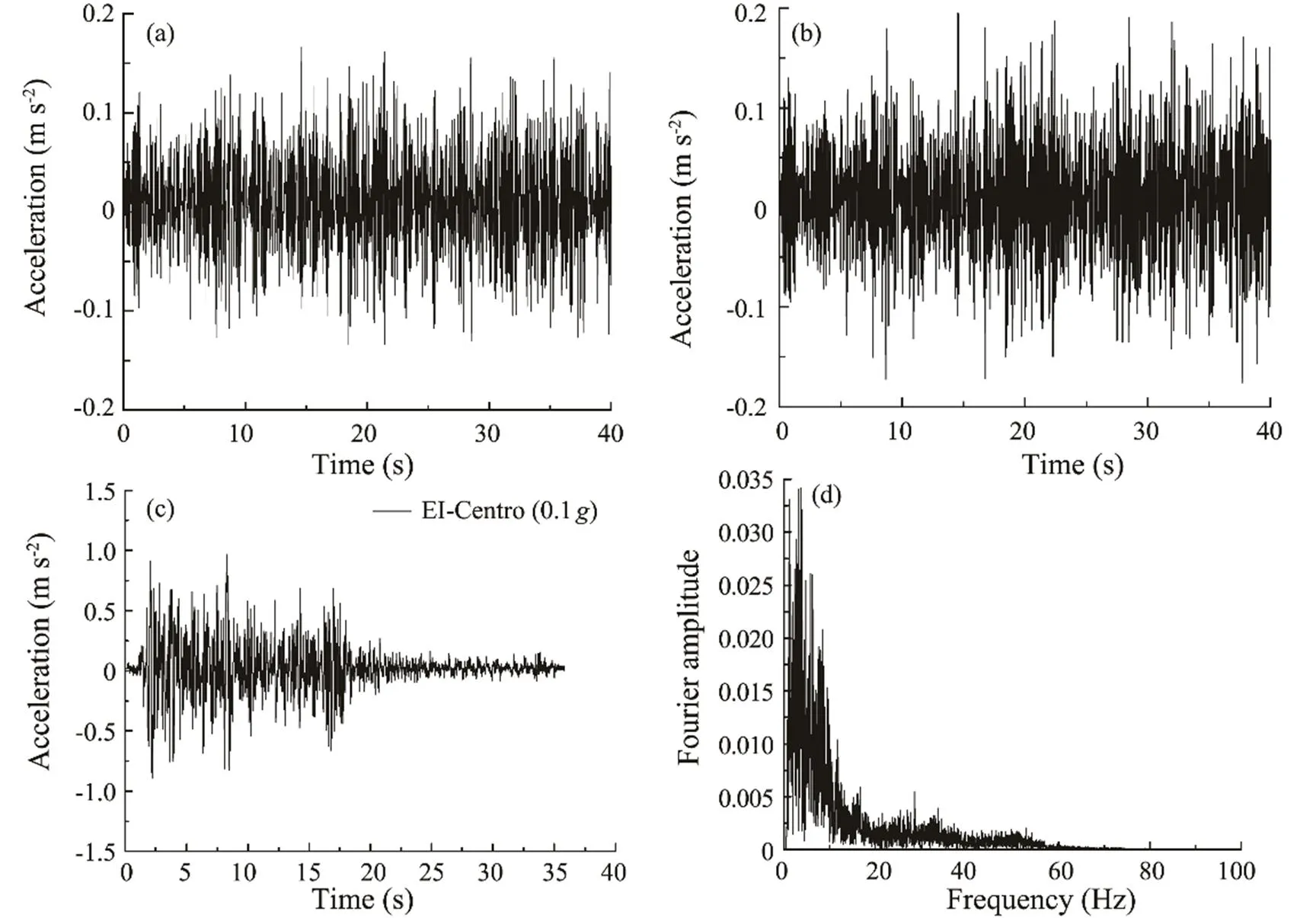
Fig.7 Information of the seismic inputs. (a), input white noise; (b), output white noise; (c) EI-Centro wave (0.1g); (d), frequency spectrum of EI-Centro wave (0.1g).

Table 4 Loading conditions
2.6 Model Positioning
The sensors were laid out after the soil samples were prepared, and the three-bucket jacket foundation model wasplaced at the fixed point. The exact position and the vibra- tion direction are depicted in Fig.9. Fig.10 comprehensive- ly describes the process of model positioning and soil sa- turation. The covers over the heads of the model buckets settled to the soil surface level after a 24h model settling process, while one of the head covers was slightly lower than the surface. Slight cracks could also be observed in the soil around the buckets during this time because the sand was dense and settled where the foundation was placed. The exhaust air in the bucket foundation produced a suction effect to further lower the foundation. The soil saturation began after the model settlement was stabilized.
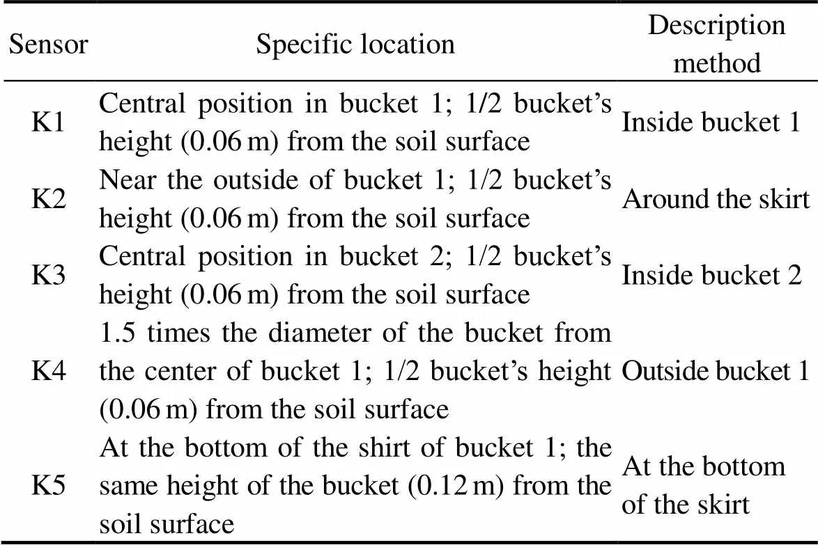
Table 5 Summary of the pore water gauge sensors

Table 6 Summary of the acceleration sensors

Fig.8 Sensors and the sensor fixation. (a), (b), pore water pressure sensors; (c), acceleration sensors; (d), sensor fixation.

Fig.9 Sensor layout. (a), front view; (b), top view.
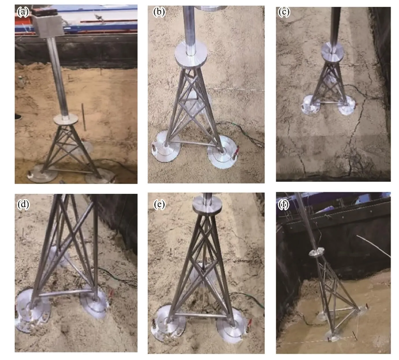
Fig.10 Process of model positioning. (a), model positioning; (b), sinking process; (c), cracks; (d), settlement; (e), settlement complete; (f), soil saturation.
3 Liquefaction Determination Criterion
3.1 Effective Stress Method
The liquefaction mechanism used in shaking table tests for the foundation soil is based on the theory of HB Seed. From the perspective of the stress state of saturated sand, the vertical effective stress of the soil decreases when the soil is subjected to an earthquake or a reciprocating dyna- mic load. The shear strength of the soil is completely lost when the value drops to 0 and can be regarded as in the initial state of saturated sand liquefaction. The liquefied soil will continuously meet this criterion again once the initial state of liquefaction is reached and can accumulate signi- ficant additional deformation. Furthermore, the range of li- quefaction will increase until the overall strength of the soil is removed and its structure is unstable or the soil de- formation becomes evident. However, the prerequisite for whether the foundation soil reaches the liquefaction state lies on whether any soil element has reached an initial stateof zero effective stress. Therefore, whether or not the effec-tive vertical stress of the soil is zero is regarded as the basis for judging soil liquefaction.
The effective principle proposed by Terzaghi indicates that the total stress acting on any section of the soil is equal to the weighted total of the stress borne by the soil particles and the water pressure. This phenomenon is the sum of the effective stress and pore water pressure. The soil is consolidated under the long-term effects of its weight before the earthquake, and the additional load of the superstructure and the pore water pressure dissipates to zero. The effective stress on the soil particles in that state is found to be equivalent to the total pressure. The originally loose soil particles are compacted during the shaking process once the earthquake excitation starts. However, the ground motion duration is too short to allow the water drainage in the pores, causing the excess pore water pressure to rise rapidly. The effective stress in the soil is zero when the excess pore water pressure approaches the total stress of the soil; that is, the saturated sand has reached the initial state of liquefaction. Therefore, from this perspective, the ratio of the excess pore water pressure after the earthquake to the total stress at the time of soil consolidation before the earthquake is the ratio of the excess pore pressure/. This parameter is regarded as the criterion for the liquefaction of saturated sand. An excess pore pressure ratio/1indicates that the liquefaction stage has been attained.
3.2 Anti-Liquefaction Shear Stress Method
Considering the infeasibility of the FE software ABAQUS in simulating the changes in pore water pressure, the anti- liquefaction shear stress method is proposed for the lique- faction judgment of sand. According to the anti-liquefaction shear stress method, the effect of the earthquake on the soil is regarded as a horizontal shear wave propagating from the bedrock in the vertical direction, which causes the time-varying seismic shear stress at different soil depths.The seismic shear stress that changes irregularly with time can be equal to the equivalent cyclic shearing stress with the number of cycles. The dynamic triaxial test on the samesoil with the same number of stress cycles can measure the dynamic shear stress required for the liquefaction, that is, the anti-liquefaction shear stress. The equivalent cycle num- ber corresponding to the seismic magnitudes is listed in Table 7. Therefore, the liquefaction can be judged by comparing the anti-liquefaction shear stress and the equivalent shearing stress (Xie, 1988).

Table 7 Equivalent cycle number
The average equivalent shearing stressτis utilized instead of the maximum amplitude of shear stressmaxto simulate the seismic effects:
The Tresca yield criterion is based on the maximum shear stress in ABAQUS. Therefore, the maximum shear stress of the soil element can be obtained through the time history curves of Tresca stress. Thus, the Tresca stress output by ABAQUS can be expressed as
where1and3respectively denote the maximum and minimum principal stress. Therefore, the maximum shear stress can be expressed as

A magnitude calibration factor−1is also introduced to consider the impact of different magnitudes (as shown in Table 8). Therefore, the equivalent shearing stress can be measured by Eq. (6) as follows:


Table 8 Magnitude calibration factor MSF−1
In the absence of experimental data, the anti-liquefaction shear stressτ, dcan be determined by an empirical formula Eq. (7):
4 Experiment Results and Analysis
4.1 Analysis of Macroscopic Phenomena
The seismic wave excitation inputs were started after the white noise sweep tests. The vibration of the laminar shear box was found behind the input of the vibration signal by approximately 1s. The laminar shear box showed only slight sloshing, the soil surface did not change signi- ficantly, and the three-bucket jacket foundation model did not tilt under a peak acceleration of 0.035from the input seismic waves. A few gas bubbles were generated on the surface of the soil outside the buckets due to the vibration as the peak acceleration reached 0.1. Bubbles appeared on the surface of the soil outside the bucket when the peak acceleration reached 0.175, while several small bubbles were generated around the bucket. The shear box vibrated violently and the maximum displacement in the horizontal direction reached 0.1m when the peak acceleration was increased to 0.22. The test model experienced a large in- clination; particularly, bucket 1 was overturned, and part of it was pulled out of the soil surface. Thus, the stability of the foundation was markedly reduced, and the tilt range ofthe foundation model gradually increased a while after the vibration. Strong sand boils and waterspouts occurred on the soil surface when the peak acceleration value reached 0.4. The inclination of the foundation model further increased, the model was finally shaken down, and the soil lost its bearing capacity altogether. The model was unplugged and the test was ended when the model fell on the laminar shear box. Fig.12 depicts the significant phenomenon during the vibration.

Fig.11 Liquefaction stress ratio.
4.2 Excess Pore Water Pressure Response
The pore water pressure sensors should be zeroed and balanced before the application of each seismic wave. The dissipation process of the excess pore water pressure was continually recorded after the loading due to the completion of a seismic waveform. Therefore, the numerical values reflected the change from the loading from seismic waves to the dissipation process of excess pore water pressure under the EI-Centro waves at each position, as plotted in Fig.13.
The excess pore water pressure inside the bucket, outside the bucket, or near the foundation during the shaking process showed the same trend of increasing to a certain level and maintaining that level for several minutes. This pressure then dissipated until the pore water pressure recovered to its original state. The fluctuation range of the excess pore water pressure increased as the acceleration rose. The excess pore water pressure slightly accumulated under the small-magnitude earthquake waves, and the lique- fied state was not reached. The excess pore water pressure ratio did not exceed 0.3 until the acceleration peak value rose to 0.1; particularly, the ratio of the sand inside the bucket (K1, K3) remained lower than 0.1. The excess porepressure significantly increased when the acceleration rea- ched 0.175; particularly, the excess pore water pressure ratio of the soil at the bottom of the skirt (K5) almost reached an initial liquefaction state of/1. The ratio of the soil outside the bucket (K4) and around the skirt (K2) both increased to 1.0 once the acceleration reached 0.22, and the excess pore water pressure inside the bucketdeveloped a large peak in a short time. The excess pore wa- ter pressure ratio of the sand inside the bucket also reached the liquefied state when the acceleration increased to 0.4. The pressure then dissipated but did not fall to its initialstate, and the recording was stopped after the model structure fell over. The sand at each measuring point was liquefied and gradually lost its bearing capacity during this time.The order in which the sand at each measuring point reached the liquefied state is as follows: At the bottom of the skirt (K5)>outside bucket 1 (K4)>around the skirt (K2)>inside buckets 1 and 2 (K1, K3). This order reveals that the dissipation rate of the excess pore water pressure at the bot- tom of the skirt was slower than that of other positions.
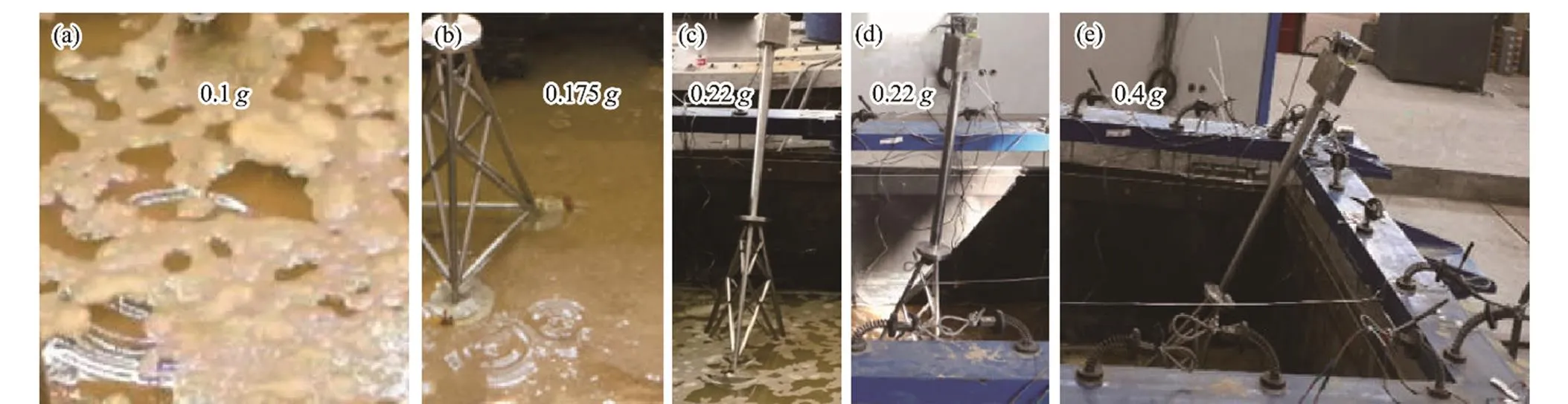
Fig.12 Vibration phenomenon at different time. (a), bubbles outside the bucket; (b), bubbles near the bucket; (c) bucket 1 pulling out; (d), model inclination; (e), model tilting.
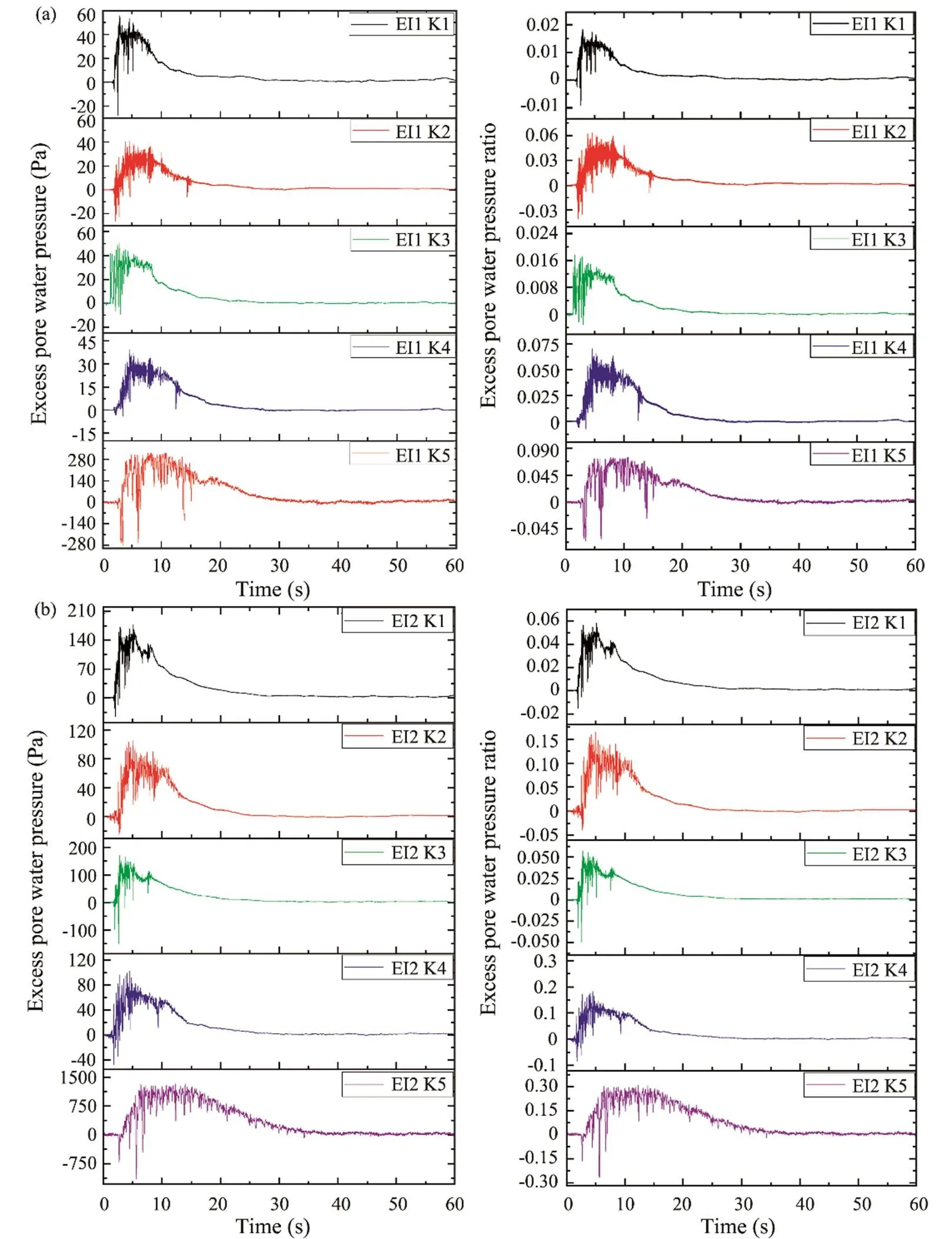
Fig.13a–b Time history of excess pore water pressure and excess pore water pressure ratio. (a), EI-Centro wave (0.035); (b), EI-Centro wave (0.1).

Fig.13c–e Time history of excess pore water pressure and excess pore water pressure ratio. (c), EI-Centro wave (0.175); (d), EI-Centro wave (0.22); (e), EI-Centro wave (0.4).
Moreover, the test soil is subjected to shear stresses causedby seismic waves during the shaking table test. At the beginning of the earthquake, the friction between soil particles is sufficient to resist the shear stress, and soil particlesretain their relative positions. Therefore, the excess pore pressures demonstrate minimal growth. As the accelerationrises, additional soil particles are distorted and moved fromtheir original equilibrium states to a suspended state due to the increased shear stresses. The pressure originally borne by soil particles transfers to water in the pores; thus, the ex- cess pore pressure at each location tends to grow rapidly as the earthquake intensifies.
The sand inside the bucket reached the liquefied state at the latest, and this phenomenon can be ascribed to two reasons. First, the existence of the foundation model and counterweight above the soil leads to a large vertical load. The effective stress of the soil in the bucket is also high. Therefore, the seismic excitation required for liquefaction is strong, and the resulting vertical force consolidation con- tributes to the anti-liquefaction behavior of the soil. Second,the soil inside the bucket is constrained by the skirt, whichis equivalent to the surrounding hoop effect. Therefore, the soil skeleton maintains stability, and the frictional force between the particles remains high. Consequently, particle misalignment and floating are difficult to induce, and the pore pressure is slightly prone to accumulation.
The sand outside the bucket was slightly constrained by the bucket foundation; thus, the soil lacked liquefaction resistance. Moreover, the effective stress of the sand was smaller than that inside the bucket due to the minimal over- burden load; thus, slight shear stresses could generate water pressure. Therefore, the sand at this location was liquefied earlier than the soil inside the bucket. Simultaneously, the excess pore water pressure ratio of the sand near the skirt slowly increased compared with that outside the bucket under the excitation of small-magnitude earthquake waves. Thus, the confinement of the three-bucket jacket foundation has a barely noticeable impact in the nearby soil outside the skirt under the small-magnitude seismic excitation.
The soil at the bottom of the skirt was markedly disturbed by the structure, and the stress concentration phenomenon occurred. The soil particles at this position were prone to distortion during the vibration process. Therefore, the sand reached the liquefied state early. The analysis of macroscopic phenomena revealed that the soil particles continuously adjusted their positions due to the generation of seismic shear stress, thus becoming suspended among the skeleton voids between the particles, which were affect- ed by pore water movement from the bottom to the top and turned upward with the water flow. In addition, the pore pressure sensor (K5) was located in the deep sandy soil where fewer paths are available for the pore water pressure to dissipate; therefore, the pore water dissipated slower than in other positions. Consequently, the pressure that the soil particles could bear and the bearing capacity of the soil was markedly reduced, and a large number of air bubbles appeared on the macroscopic scale. Part of the soil at the bottom of the skirt also lost its stability in the liquefied layer.
Fig.13 shows that the instantaneous negative pore pressure phenomenon occurred at the moment before the excess pore water pressure generated its plateau, which was aggravated by the increasingly intense seismic waves. This phenomenon was first recorded by Ogawa. (2001) at the National Institute of Earthquake and Disaster Preventionshaking table tests of soil-pile dynamic interactionmodel of liquefaction sites. The aforementioned phenomenon was also reported by Ling. (2003) in his large- scale shaking table 1:10 model test for free-ground liquefaction from earthquakes in Tongji University. Previous research indicates that this phenomenon is caused by the instant expansive action of the soil before the acceleration reaches its plateau. Therefore, the pore water pressure mea- sured for a short time is not positive pressure but suction. Consequently, the instantaneous pressure is negative.
4.3 Seismic Acceleration Response
Earthquake wave propagates upward from the bedrock to the structure by the site soil as a medium. The site soil has the effects of amplifying and filtering seismic excitations according to elastic wave propagation theory. Therefore, these effects will increase the amplitude of the seismic waves when the excitations pass through the uniform elastic soil and reach the surface. This phenomenon is called the amplification effect. The concept of acceleration amplification coefficient is introduced, that is, the ratio of the peak value of acceleration at the measuring point to that of the input seismic waves, to study the amplification effect of the soil on the acceleration intuitively.
Two sets of acceleration sensors were arranged in the center of bucket 1 and a certain distance away from bucket1 to examine the influence of the three-bucket jacket foundation on sand acceleration response and the law of acceleration amplification along the depth direction during the earthquake. The two sets of sensors, namely=0 and=1.5D (where D is the diameter of the bucket), were used to represent the distance from the center of bucket 1, and each group had four acceleration sensors arranged in the vertical direction, as depicted in Fig.9. Figs.14 and 15 respectively illustrate the time history curves of the acceleration response at each measuring point and the accelera- tion amplification coefficient curves with depth.
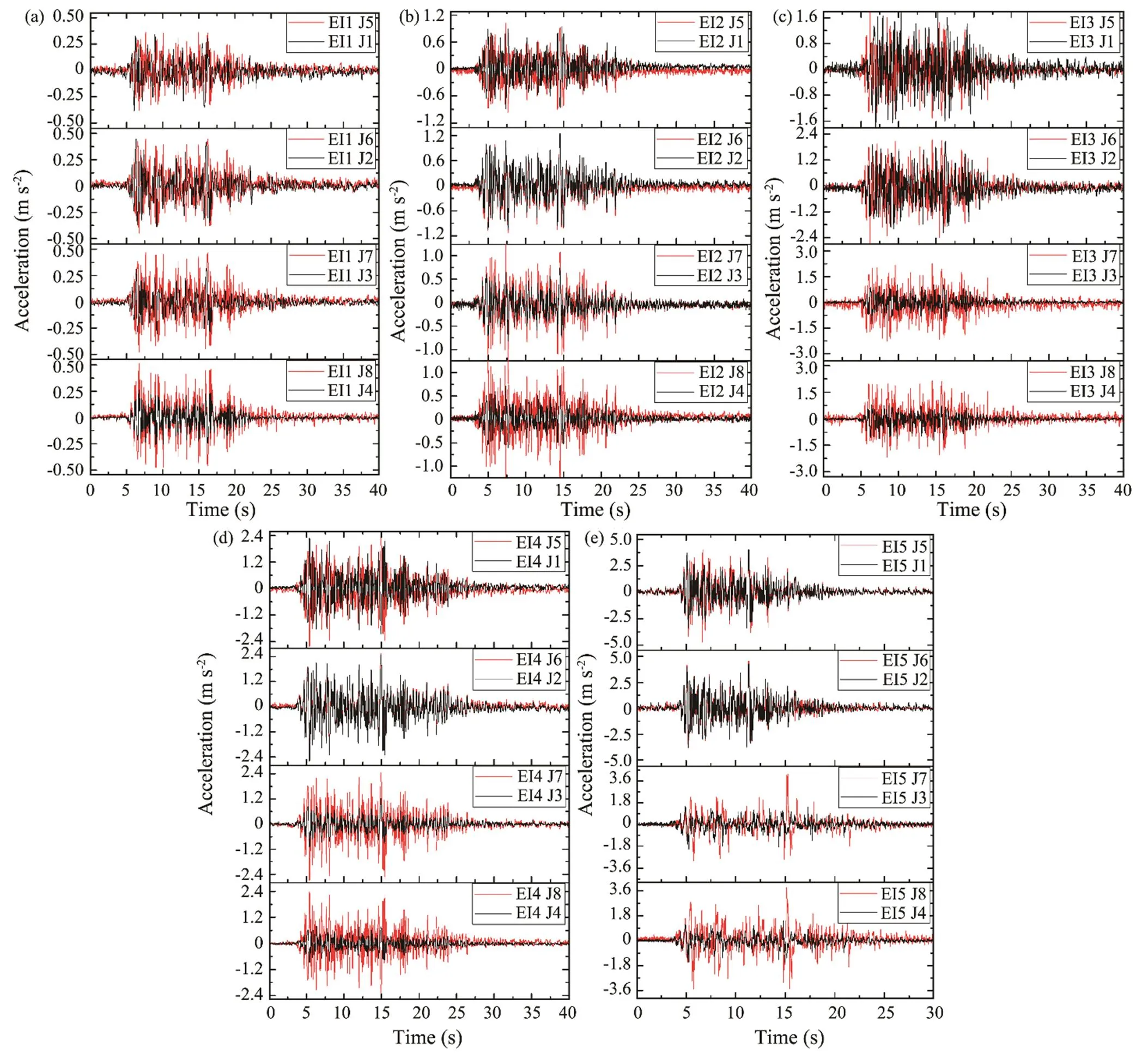
Fig.14 Time history of acceleration at each measuring point. (a), EI-Centro wave (0.035g); (b), EI-Centro wave (0.1g); (c), EI- Centro wave (0.175g); (d), EI-Centro wave (0.22g); (e), EI-Centro wave (0.4g).

Fig.15 Acceleration magnification coefficient curves. (a), acceleration magnification coefficient at Y=0; (b), acceleration magnification coefficient at Y=1.5D.
The comparison of acceleration responses of the two axes revealed that the peak acceleration of sand inside the bucket is substantially inhibited and no longer follows the law of development of sand liquefaction in the free field. In- stead, the sand in the height range of the bucket foundation (0.06–0.12m) liquefies later than that in the free field at the same height and reacts slightly to the seismic excitations. However, the restraint of the three-bucket jacket foundation on the soil inside and around the bucket decreases with depth.
As plotted in Fig.15, the acceleration amplification coef- ficient of the sand outside the bucket (=1.5D) increases with the height of the measuring point under the small- magnitude earthquake waves. A significant increase in acceleration response on the surface was observed when the input acceleration was 0.035g. However, the acceleration amplification coefficient of the sand in the center of the bucket (=0) demonstrates a different tendency that increases first and then decreases from bottom to top. The acceleration amplitude of the sand in the height range of the bucket foundation (0.06–0.12m) is restrained by the foundation. Therefore, the acceleration amplification coef- ficient is approximately half of that at the same height outside the bucket. The three-bucket jacket foundation also has a noticeable impact on the acceleration response of sand and can effectively reduce the dynamic response of the soil around the foundation. The acceleration amplification coefficient of the sand outside the bucket experiences a different variation trend that increases originally and then decreases with depth under the rising magnitude of ace- leration. The extent of reduction of the coefficient also expands near the soil surface.
Notably, the peak acceleration and the acceleration amplification coefficient of sand under the small-magnitude earthquake waves are relatively larger than those under large seismic excitations. This phenomenon is due to the elastic state of the soil and its violent reaction to earthquake excitations under small shakings. The SSI exhibits a non- linear state as the magnitude of the earthquake increases; therefore, part of the sand reaches an initial liquefaction state with low shear resistance and large shear strain, which substantially weakens its seismic response. Sand liquefac- tion begins at the shallow layer and then progresses down- ward. Therefore, a shallow soil layer leads to a high lique- faction degree, and the liquefied soil layer has a signifi-cant effect in absorbing a certain amount of seismic wave energy and reducing the amplification effect.
5 Numerical Simulation Results and Analysis
5.1 FE Model
The FE model of the three-bucket jacket foundation was developed in the ABAQUS software package. Instead of a guide for engineering practice, the FE model was used to study the influence mechanism of this foundation form on soil liquefaction resistance and the development of soil li- quefaction and compare the results with experimental data to verify the reliability. Therefore, model size was used for FE modeling.
The size of the FE model was the same as that in the foundation model used in the shake table test, with a mo- deled diameter of 159mm and a bucket height of 120mm. The material model was steel. The foundation soil model used a circular profile with a diameter of 2m and a height of 1.5m to facilitate the meshing process. The parameters of the soil referred to the experimental sand, as listed in Table 3. The Mohr-Coulomb elastoplastic constitutive mo- del was employed in the model development. In addition, the direction of the seismic waves in the shaking table test is parallel to the-axis direction, and the positions and numbers of the bucket foundations were set up to match the shaking experiments, as shown in Fig.16a.
The acceleration time histories, which were equivalent to a fixed boundary, were directly applied to the bottom of the model. Only the displacement perpendicular to the vibration direction was limited for the side boundary. Simultaneously, the equation constraint command was used to simulate the motion consistency of the soil at the opposite face of the frame at the same depth to replicate the motion of the laminar shear box in the shaking table tests and reflect the real shear deformation of the soil. The relative dis- placement between the soil elements on opposite faces at the same depth was limited to zero based on the set motion equation, as shown in Figs.16b–c.
5.2 Effective Initial Stress Calculation
Fig.17 depicts the initial effective stress nephogram after soil consolidation, as calculated in the FE model. The initial effective stress of the soil calculated by FE was used to compute for the excess pore water pressure ratio in Section 4.2 and the vertical effective stress of the soil in Section 5.3. The effective stress cloud diagram shows that stress concentration occurs at the bottom of the bucket, indicating the possible occurrence of local liquefaction in this area. The measuring point K5 was selected in the shak- ing table test due to the aforementioned occurrence.

Fig.16 Finite element model. (a), three-bucket jacket foundation and soil model; (b) equation constraint settings; (c), equation parameters.
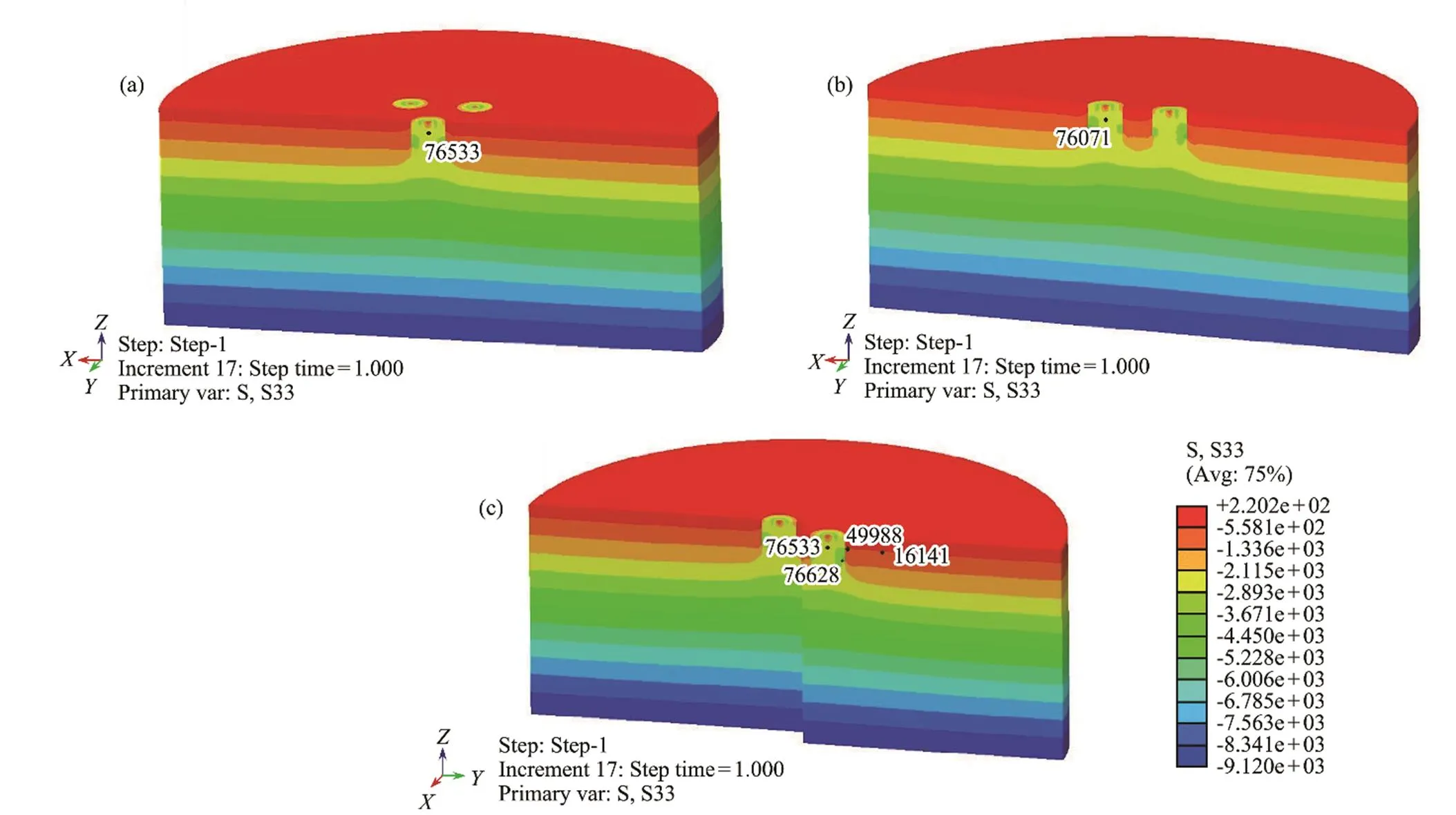
Fig.17 Cloud plot of initial effective stress. (a), section perpendicular to Y-axis of bucket 1; (b), section perpendicular to Y-axis of buckets 2 and 3; (c), section parallel to Y-axis of buckets 1 and 2.
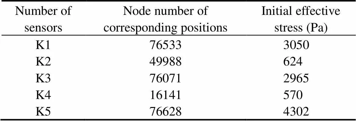
Table 9 illustrates the initial effective stress of the soil elements at corresponding positions extracted from the FE model for comparison with the excess pore water pressure at each measuring point obtained from the shaking table test.
5.3 Tresca Stress and Liquefaction Determination
Based on the anti-liquefaction shear stress method described in Section 3.2, the anti-liquefaction shear stress was calculated in accordance with the empirical formula, and the Tresca stress was outputted through ABAQUS post- processing to obtain the equivalent shearing stress. The occurrence of liquefaction can be judged by comparing the two stresses. Only the acceleration peak value of 0.22of the EI-Centro wave was simulated in this paper due to the length of the article. The soil elements were selected as the arrangement position of the pore water pressure sensors in the shaking table test, that is, inside the bucket, away from the bucket, around the skirt, and at the bottom of the skirt, to investigate the influence of the three-bucket jacket foundation on soil liquefaction. Fig.18 depicts the time histories of Tresca stresses of each position, and the calculation results are listed in Table 10.
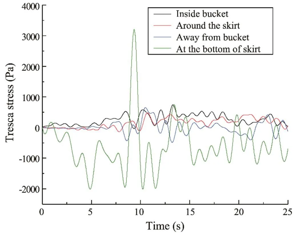
Fig.18 Time histories of Tresca stresses.
Tresca stresses reflect the strength of the earthquake action on the soil during seismic excitations. As the soil elements at the bottom of the skirt are disturbed by the bucket wall, the shear stress is at a substantially higher level than that of other parts, and the fluctuation range is relatively large. This finding proves that the structure and soil have a violent interaction during the vibration process, which causes soil particle distortion. The aforementioned result also explains that the soil in this area reached the liquefied state substantially early in the shaking table test. A slight difference is observed between the peak value of the shear stresses of the soil element outside the bucket and that of the sand inside the bucket and near the skirt, as plotted in Fig.18. The soil at this location is not restricted by any additional load; thus, the fluctuation range of the Tresca stress is larger than that in the two other areas. In addition, no counterweight is found above the soil at this location; therefore, its initial stress and the anti-liquefaction shear stress are relatively small. Slight shear stresses can generate water pressure and cause the liquefaction of the sand. The average shear stress value of the soil element at this location is less than that inside the bucket, but the liquefaction occurs early.

Table 10 Calculation results of the anti-liquefaction shear stresses and the equivalent shearing stresses
The soil near the skirt is compacted due to the settlementof the bucket foundation. Thus, the initial stress is relative- ly larger than the soil outside the bucket. The maximum shear stress value is similar, but the liquefaction degree of the soil near the skirt is less than that outside. In addition, the interaction between the foundation and soil aggravates the mutual displacement of the soil particles in this area during the vibration process. Therefore, the average shear stress value is larger than that outside the bucket.
The restriction effect complicates the fluctuation of Tresca stress of the soil element inside the bucket. The additional load of the upper structure also leads to large initial stresses and anti-liquefaction shear stresses. Therefore, the soil in- side the bucket liquefies at the latest despite the maintainedhigh level of average equivalent shearing stress value. The restriction effect of the bucket foundation and the additional load on the upper part demonstrate a significant im- provement in the liquefaction resistance of the sand inside the bucket and have a certain effect on the sand around the bucket. Correspondingly, sand liquefaction appears later, and the degree of liquefaction is also small.
5.4 Simulation Results of the Acceleration
The acceleration time histories of the soil element at thecorresponding position of the acceleration measuring points in the shaking table test are plotted in Fig.19. In this paper, two working conditions were selected: EI1 as the small- magnitude earthquake and EI4 as the large-magnitude earth- quake.
The FE simulation results of small waves are better than those of large excitations, while the simulation results of the axis=0 are superior to those of=1.5D. The numeri- cal simulation results are slightly smaller than the experimental ones, especially at around 15s when a short-termpeak in acceleration measured in the shaking table tests doesnot appear in the numerical simulation results. Overall, the numerical simulation results of acceleration are relatively credible.
Fig.20 depicts the acceleration magnification coefficientsof the two axes=0 and=1.5D under various conditions to compare the influences of three-bucket jacket foundations on the acceleration responses of the sand inside and outside the bucket. The experimental and numerical simulation results of acceleration response display the same trend under the excitations of small-magnitude earthquakes:that is, the peak acceleration of the sand outside the bucket gradually increases from bottom to top, while that of the sand inside the bucket increases originally and then decreas- es with depth. This finding indicates that the three-bucket jacket foundation has a significant inhibitory effect on the acceleration response of the sand. The numerical simulation result of the sand outside the bucket experiences a different trend from the experimental resultswhen the peak acceleration reaches 0.175. The acceleration response of sand exhibits a weakness effect, which is not displayed in the FE simulation results due to the liquefaction. Consequently, the acceleration amplification factor was reduced in the shaking table test. This finding is probably due to the change in stiffness of the sandy soil once the liquefied state is reached and the prominence of the non-linear characteristics, which cannot be simulated accurately by the FE software.
6 Conclusions
Using the shaking table tests and three-dimensional FE software for modeling, different magnitudes of simulated earthquake waves were used as inputs to the shaking table to simulate seismic excitations and evaluate the seismic response and liquefaction of the sand near the foundation. Two liquefaction determination criteria were then applied to judge the liquefaction. The development law of the soil’samplification effect on seismic acceleration and the seismic response of the soil under various magnitude earthquake waves were also discussed in this paper. The conclusions are as follows.
1) The weight and counterbalance of the foundation model result in a larger initial load on the soil inside the bucket than that nearby and outside the skirt, and the vertical forcehelps with the liquefaction resistance of the soil. The hoop restraint effect of the bucket foundation during the earthquake shaking complicates the development of the excess pore pressure inside the bucket and demonstrates a weak effect on the acceleration response, which effectively improves the anti-liquefaction capability of the sand. How- ever, the confinement has a barely noticeable impact on the nearby soil outside the skirt.
Fig.20a–b Comparison of experimental and FE results of acceleration magnification coefficient. (a), EI-Centro wave (0.035); (b), EI-Centro wave (0.1).
Fig.20c–f Comparison of experimental and FE results of acceleration magnification coefficient. (c), EI-Centro wave (0.175); (d), EI-Centro wave (0.22); (e), EI-Centro wave (0.4).
2) The soil outside the bucket easily reaches the liquefaction state due to the small vertical load and reduced re- striction effects. A strong SSI is also found at the bottom of the skirt. Therefore, the phenomenon of soil liquefaction occurs earlier than that in other positions, and the excess pore water pressure dissipates slowly.
3) The acceleration amplification coefficient of the sandoutside the bucket increases with depth, but that of the sand inside the bucket is substantially inhibited in the height range of the bucket foundation. This finding proves that three-bucket jacket foundations have a noticeable impact on the acceleration response of sand and can effectively reduce the dynamic response of the soil around the foundation. The liquefied soil layer has a significant effect in absorbing a certain amount of seismic wave energy and reducing the amplification effect.
4) The numerical simulation results are consistent with the phenomenon and data measured during the shaking table test, except that the seismic response of the soil after liquefaction under the large-magnitude seismic excitation cannot be accurately simulated. This paper verifies the fea-sibility of the excess pore water pressure ratio and the anti- liquefaction shear stress method for judging soil liquefaction.
5) The phenomenon of instantaneous negative pore pressure emerged during the earthquake shaking tests, and si- milar phenomena have been recorded in previous experiments. However, further study is necessary to find specific reasons.
Acknowledgement
This work was supported by the National Natural Science Foundation of China (No. 52171274).
Alati, N., Failla, G., and Arena, F., 2015. Seismic analysis of off- shore wind turbines on bottom-fixed support structures., 373 (2035): 20140086.
Asheghabadi, M. S., Sahafnia, M., Bahadori, A., and Bakhsha- yeshi, N., 2019. Seismic behavior of suction caisson for offshore wind turbine to generate more renewable energy., 16 (7): 2961-2972.
Ding, H., Hu, R., Zhang, P., and Le, C., 2020. Load bearing be- haviors of composite bucket foundations for offshore wind turbines on layered soil under combined loading.,198: 106997.
Ding, H., Liu, Y., Zhang, P., and Le, C., 2015. Model tests on the bearing capacity of wide-shallow composite bucket foundations for offshore wind turbines in clay., 103: 114-122.
Ding, H., Zhang, C., and Hang, X., 2007. Analysis of clay soil softening in ice-induced vibration of bucket foundation platform., 3: 369-371 (in Chinese with English abstract).
Emdadifard, M., and Hosseini, S. M. M. M., 2010. Numerical modeling of suction bucket under cyclic loading in saturated sand., 15: 1- 16.
Fu, D., Zhang, Y., Yan, Y., and Jostad, H., 2020. Effects of tension gap on the holding capacity of suction anchors., 69: 102679.
Huo, T., Tong, L., and Zhang, Y., 2018. Dynamic response analysis of wind turbine tubular towers under long-period ground mo- tions with the consideration of soil-structure interaction., 14 (2): 227-250.
Ju, S. H., and Huang, Y. C., 2019. Analyses of offshore wind tur- bine structures with soil-structure interaction under earthquakes., 187: 106190.
Karimi, Z., and Dashti, S., 2016. Numerical and centrifuge mo- deling of seismic soil-foundation-structure interaction on lique-fiable ground., 142 (1): 04015061.
Ku, C. Y., and Chien, L. K., 2016. Modeling of load bearing cha- racteristics of jacket foundation piles for offshore wind turbines in Taiwan., 9 (8): 625.
Li, D., Zhang, Y., Feng, L., and Gao, Y., 2014. Response of skirted suction caissons to monotonic lateral loading in saturated medium sand., 28 (4): 569-578.
Li, D., Zhang, Y., Feng, L., and Gao, Y., 2015. Capacity of modified suction caissons in marine sand under static horizontal loading., 102: 1-16.
Ling, X., Wang, C., Wang, Z., Wang, C., and Wang, D., 2003. Study on large-scale shaking table proportional model test for free-ground liquefaction arisen from earthquake., 23 (6): 138-143.
Ogawa, N., Ohtani, K., Katayama, T., and Shibata, H., 2001. Con- struction of a three-dimensional, large-scale shaking table and development of core technology., 359 (1786): 1725-1751.
Prowell, I., 2011. An experimental and numerical study of wind turbine seismic behavior. PhD thesis. University of California.
Randolph, M. F., May, M., Leong, E. C., Hyden, E. C., and Murff,J. D., 1992. Soil plug response in open-ended pipe piles., 118 (5): 743-759.
Ren, Y., Vengatesan, V., and Shi, W., 2022. Dynamic analysis of a multi-column TLP floating offshore wind turbine with tendon failure scenarios., 245: 110472.
Seong, J. T., Ha, J. G., Kim, J. H., and Park, H. J., 2017. Centrifuge modeling to evaluate natural frequency and seismic behavior of offshore wind turbine considering SFSI.,20 (10): 1787-1800.
Wang, X., Zeng, X., and Li, J., 2019a. Vertical performance of suction bucket foundation for offshore wind turbines in sand., 180: 40-48.
Wang, X., Zeng, X., Li, X., and Li, J., 2020. Liquefaction cha- racteristics of offshore wind turbine with hybrid monopile foun- dationcentrifuge modelling., 145: 2358- 2372.
Wang, X., Zhang, P., Ding, H., and Liu, Y., 2019b. Experimental study on wide-shallow composite bucket foundation for offshore wind turbine under cyclic loading., 37 (1): 1-13.
Wang, Y., Shi, W., Michailides, C., Wan, L., Kim, H., and Li, X., 2022. WEC shape effect on the motion response and power performance of a combined wind-wave energy converter., 250: 111038.
Xie, D., 1988.. Xi’an Jiaotong University, Xi’an, 203-213.
Zhang, J., Zhang, L., and Lu, X., 2007. Centrifuge modeling of suction bucket foundations for platforms under ice-sheet-induced cyclic lateral loadings., 34 (8-9): 1069- 1079.
Zhang, L., Qiu, W., and Jiang, T., 2014. Shaking table model de- sign under circumstances of similarity ratio is not strictly proportional., 26 (5): 421-425 (in Chinese with English abstract).
Zhang, P., Xiong, K., Ding, H., and Le, C., 2014. Anti-liquefaction characteristics of composite bucket foundations for offshore wind turbines., 6 (5): 053102.
J. Ocean Univ. China(Oceanic and Coastal Sea Research)
https://doi.org/10.1007/s11802-022-4742-7
ISSN 1672-5182, 2022 21 (3): 719-736
(August 28, 2020;
October 30, 2020;
January 29, 2021) © Ocean University of China, Science Press and Springer-Verlag GmbH Germany 2022
Corresponding author. E-mail: zpy_td@163.com
(Edited by Chen Wenwen)
 Journal of Ocean University of China2022年3期
- Journal of Ocean University of China的其它文章
- Effect of Intertidal Elevation at Tsuyazaki Cove, Fukuoka,Japan on Survival Rate of Horseshoe Crab Tachypleus tridentatusEggs
- Asian Horseshoe Crab Bycatch in Intertidal Zones of the Northern Beibu Gulf: Suggestions for Conservation Management
- Experimental Investigation on the Interactions Between Dam-Break Flow and a Floating Box
- Variational Solution of Coral Reef Stability Due to Horizontal Wave Loading
- High Microplastic Contamination in Juvenile Tri-Spine Horseshoe Crabs: A Baseline Study of Nursery Habitats in Northern Beibu Gulf, China
- Influence of Autonomous Sailboat Dual-Wing Sail Interaction on Lift Coefficients