
Study on Wave Added Resistance of Ships in Oblique Waves Based on Panel Method
2022-06-14 06:13WANGXujieZHANGRiZHAOJingandCAOPengfei
WANG Xujie, ZHANG Ri, *, ZHAO Jing, and CAO Pengfei
Study on Wave Added Resistance of Ships in Oblique Waves Based on Panel Method
WANG Xujie1), ZHANG Ri1), *, ZHAO Jing2), and CAO Pengfei3)
1)College of Engineering, Ocean University of China, Qingdao266100, China 2) College of Electromechanical Engineering, Qingdao University of Science and Technology,Qingdao266100, China 3)Shipping Center, Ocean University of China,Qingdao266100, China
When the ship is sailing at sea, wave added resistance has great influence on the rapidity and economy of the ship. With the increasing pressure of energy and environmental protection, IMO has proposed the EEDI formula of the newly built ships, which restricts the energy consumption standard of civil ships more strictly. Therefore, a panel method based on three dimensional potential flow theory is proposed to study the problem of wave added resistance in this paper. Firstly, the method solves the motion responses of the ship in the time domain, and then calculates the wave added resistance of the ship by near-field pressure integration method. The wave added resistance of S175 container ship in head and oblique waves are calculated and compared with the experimental data, and the accuracy of the proposed method are verified. At last, the influence of Froude number and wave direction angle on wave added resistance is studied. The proposed method provides an approach of satisfactory accuracy and efficiency for the development of high-performance new ship forms, optimization of ship hull lines, comprehensive performance evaluation of ships and practical navigation guidance.
wave added resistance; oblique wave; panel method; potential flow theory
1 Introduction
Wave added resistance of a ship is the increased resi- stance by waves compared to resistance in calm sea, and its magnitude even could reach 10%–30% of calm water resistance (Arribas, 2007).In order to improve the energy efficiency of ships and reduce carbon emissions, the IMO has issued more and more strict regulations,so many scholars have carried out research on the accurate pre- diction of wave added resistance. At present, the resear- ches on wave added resistance are mainly focused on the condition of sailing in head waves, but in actual navi- gation, ships rarely travel in head waves. Thus, in order to properly evaluate the motion and energy consumption of ships in actual navigation, it needs further research on calculation method of wave added resistance in oblique waves.
There are three main methods to study wave added resistance:methods based on potential flow theory, me- thods based on viscous flow theory and experiments. The analytical approaches to wave added resistance based on potential flow methods can be generally classified into two categories: the far-field method and the near-fieldmethod. The far-field method based on the momentum conservation theory was firstly introduced by Maruo (1960). It was further elaborated by Newman (1967), Ge- rritsma and Beukelman (1972) and Salvesen (1978). Ka- shiwagi (2010) used Maruo’s approach to calculate added resistance by applying enhanced unified theory, and intro- duced a correction factor in the diffracted wave com- ponent at short wave lengths. Liu. (2011) applied a developed hybrid Rankine Source-Green function method to calculate the motion responses of the ship, and then obtained the wave added resistance by Maruo’s approach. The far-field method is simple and efficient, but there are difficulties in handling a proper control surface. The near-field method which directly integrates the steady second-order pressure acting on the wetted hull surface was pro- posed by Boese (1970). At the early stages, many scho- lars calculated the wave added resistance of ships based on strip theory, such as Faltinsen. (1980), Grue and Biberg (1993). Recently, 3D time/frequency domain boundary element methods have been widely applied. Söding. (2014) calculated the wave added resistance based on a frequency domain Rankine panel method, with considering the dynamic squat of the ship and the effects of the non- linear steady flow caused by forward speed. Hong. (2016) computed the wave added resistance of the ship based on a three-dimensional translating and pulsating source panel method. Park. (2016) used Rankine source me- thod to solve the motion responses of the ship in head waves, and obtained wave added re- sistance by near-field method with good accuracy. Wang. (2020) used a three-dimensional panel method to calculate the motion responses and wave added resistance of a deep-V hybrid monohull in head waves,then analy- zed the resistance reduction mechanism of the appendage. Duan. (2021) developed a numerical method for solving 3D unsteady potential flow problem of ship advancing in oblique waves. The simple Green function and transient free-surface Green function were used to form the boundary integral equation (BIE) for the inner and outer domains, then the Taylor expansion boundary element method (TEBEM) was adopted to solve the double-body flow and unsteady flow BIE.
As the rapid development of computing power, compu- tational fluid dynamics (CFD) methods are now increa- singly applied to calculate wave added resistance. Orihara and Miyata (2003) solved the Reynolds-averaged Navier- Stokes (RANS) equation by using a finite volume method (FVM), and developed a CFD that could calculate the wave added resistance of the ship. Guo. (2012) pre- dicted the motion responses and wave added resistance of the KVLCC2 ship in head waves using RANS equation. Sadat-Hosseini. (2013) calculated the motions and wave added resistance for KVLCC2 in head waves based on an Unsteady Reynolds-averaged Navier-Stokes (URANS) approach.Tezdogan. (2015) predicted the wave added resistance of the KCS containership in head waves using CFD software and estimated the effective power and fuel consumption of the ship. Yang and Kim (2017) developed a Cartesian-grid-based method for solv- ing the Euler equation, and investigated the wave added resistance of KVLCC2 with different bows. Chen. (2020) calculated the wave added resistance and motions of an icebreaker in regular waves by CFD and nonlinear potential methods. However, there are still some limita- tions in the application of CFD method, such as high computational costs and strong dependency on the user’s experience.
In the past fewdecades, many experimental studies have been conducted on wave added resistance of ships. in the initial research, the wave added resistance of some classic ships were measured forimproving the experi- mental testing technology and verifying the numerical results, such as the Series 60 ship (Gerritsma and Beu- kelman, 1972), the S175 container ship (Fujii and Taka- hashi, 1975), and the wigley hull (Journee, 1992). In re- cent years, the research on wave added resistance main- ly focused on the reduction of added resistance by chang- ing hull forms or attaching appendages. Hirota. (2004) and Kuroda. (2012) studied the effect of changes in bow shape on wave added resistance. The mo- tion responses and wave added resistance of some special ships have been also studied by experiments. Valanto and Hong (2015) measured the wave added resistance of the HSVA cruise ship. Stocker (2016) obtained the wave added resistance data of the KCS ship in different in- cident waves through experiments. Kim. (2019) conducted model test and numerical calculation on the wave added resistance of a LNGC, and analyzed the characteristics of the results. Although the experimental results are more accurate, the requirements of measure-ment technology are stricter and the cost are also higher.
In the previous research, the hydrodynamic software AQWA based on panel method was used to calculate the ship’s wave added resistance in head waves, and the numerical results have a reasonable agreement with the experimental data. In this paper, the motion responses and wave added resistance of S175 container ship sailing in several wave directions are calculated, and the feasibility of the method is verified by comparing the calculated results with the experimental data. Finally, the characteristics of ship motions and the variation of wave added resistance under different waves are analyzed.
2 Basic Formulation
A Cartesian coordinate system-is introduced, with the origin placed at the center of a ship and on the undisturbed free surface, as shown in Fig.1. The–plane coincides with the calm water free surface with the-axis pointing towards the bow and the-axis pointing upwards. The translatory displacements in the,anddirections are1(surge),2(sway) and3(heave), and the angular displacements of rotational motion about the,, andaxes are4(roll),5(pitch) and6(yaw) respectively. The angle between incident wave and-axis is, and the wave amplitude isζ, the circular frequency of wave is0. In this case, the encounter frequency is given by0−0cos, where0is the wave number of incident wave and equal to02, withthe acceleration due to gravity.

Fig.1 Coordinate system.

The periodic potential can be separated into three parts: the incident wave potential, the diffraction potential and the radiation potential:

where0is the incident wave potential,7is the diffraction potential of the restrained ship,is the normalized velocity potential due to forced motions in six degrees of freedom,is the complex amplitude of theth degree of freedom.
For diffraction and radiation wave potential, the boun- dary value problem to be solved is:

The boundary element method based on three-dimen- sional source and sink distribution theory can be used to solve the above velocity potential. The velocity potential can be expressed as:

where σ is source strength,is wetted surface, (,,) is the coordinate of the field point in the flow field, (,,) is the coordinate of the source point on,is Green’s function.satisfies all boundary conditions, and can be expressed as:
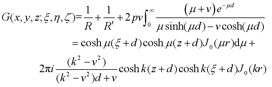


whereis the principal value of the integral,0is the first term of the Bessel function.
Then the first-order hydrodynamic pressure distribution of the hull can be obtained from the Bernoulli equation as follow:

By integrating the pressure along the wetted surface of the hull, the hydrodynamic force acting on the hull can be obtained. The longitudinal component of the hydrodynamic force is wave added resistance, which can be divided into three parts: incident force, diffraction force and radiation force.


where0kis incident force,7kis diffraction force,is the radiation force ofdirection when floating body moving at unit velocity indirection.
The differential equation of motion of a ship advancing in regular waves is:

whereMis structural mass matrix,Mis hydrodynamic additional mass matrix,is linear damping matrix of the system,Kis total stiffness matrix of the system,is wave force on the system,is response amplitude operator (RAO),is encounter frequency.
3 Hull Geometry Model
The ship model used in this paper is the S175 container ship. It is one of the benchmark hull forms used to study seakeeping capability and resistance performance by several researchers. Table 1 provides the main particulars of the S175 container ship and Fig.2 shows the body plans.

Table 1 Main particulars of S175 container ship

Fig.2 The body plan of S175 container ship.

Fig.3 Model and grids of S175 container ship.
4 Numerical Validations and Discussion
When a ship is sailing at sea, the wave angle may vary from 0 to 360 degrees. Therefore, the ship may be in the state of head waves, head quarter waves, beam waves, following quarter waves and following waves. When sai- ling in the beam waves, the ship is easy to capsize due to its violent rolling motion. When sailing in the following waves, it is prone to dangers such as losing control of cour- se and large heeling. In actual navigation, it is necessary to avoid sailing in the above two wave directions. Therefore, this paper studies only three wave directions: head waves, head quarter waves and following quarter waves. Consi- dering the symmetry of ship hull, this paper calculates and analyzes the motion responses and wave added resistance of S175 container ship with=0.15, 0.25 and=180˚, 150˚, 30˚.
In this paper, the motion responses and wave added resistance of S175 container ship are solved quickly based on panel method by AQWA. Firstly, the response ampli- tude operators (RAOs) of the ship under different Froude numbers and wavelengths are calculated. Then the ship’s motion responses and the wave force under the selected Froude numbers and wavelengths are calculated in time domain. Finally, the time history curves of motion res- ponses and wave added resistance are obtained. And the effectiveness and accuracy of the proposed method are verified by comparing the calculated results with the expe- rimental values.
4.1 Motion Responses and Wave Added Resistance in Head Waves
Firstly, the motion responses and wave added resistance of S175 container ship advancing in regular head waves (=180˚) with=0.15 and 0.25 are calculated. The range ofis 0.5–2.5, whereis wave length andis ship length between perpendiculars. The wave amplitudeζis 1.5m. Due to the symmetry of the hull and the flow field, the transverse motion response of the ship is close to zero. Therefore, only the heave and pitch motions of the ship are calculated in head waves.
Due to the limitation of space, the paper only gives the time history curves of ship motions and longitudinal force when the added resistance reaches the maximum value at each Froude number. Figs.4 and 5 present time histories of computed heave and pitch motions of S175 container ship sailing in regular head waves with=0.15,/=1. Fig.6 presents time history of computed longitudinal wave force on the ship.

Fig.4 Heave response of S175 container ship. β=180˚, Fn=0.15, λ/L=1.0.

Fig.5 Pitch response of S175 container ship. β=180˚, Fn=0.15, λ/L=1.0.
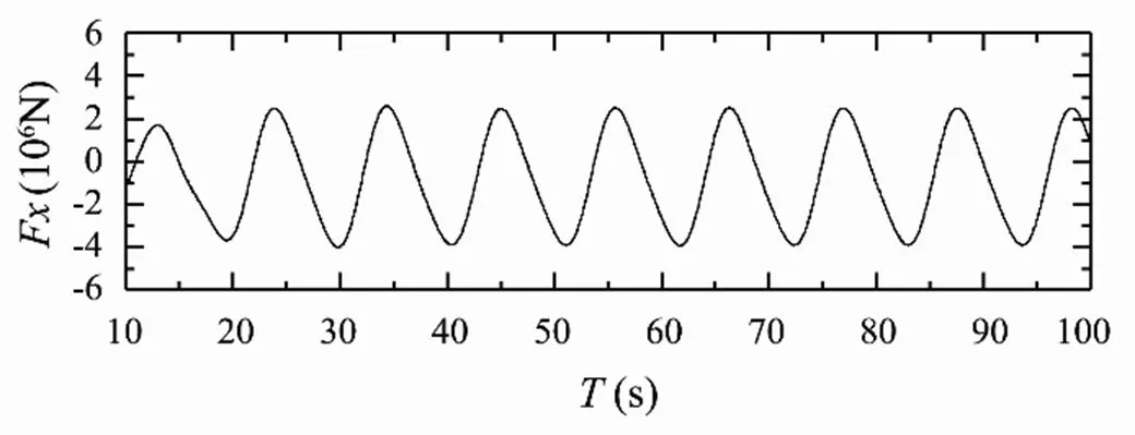
Fig.6 Longitudinal wave force of S175 container ship. β=180˚, Fn=0.15, λ/L=1.0.
Figs.7 and 8 present time histories of computed heave and pitch motions of S175 container ship sailing in regular head waves with=0.25,/=1.1. Fig.9 presents time history of computed longitudinal wave force on the ship under this condition.
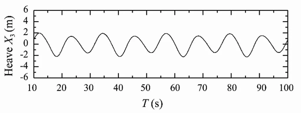
Fig.7 Heave response of S175 container ship. β=180˚, Fn=0.25, λ/L=1.1.
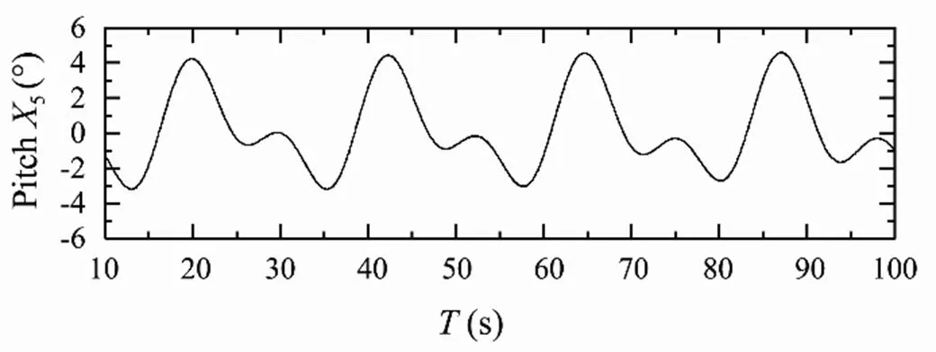
Fig.8 Pitch response of S175 container ship. β=180˚, Fn=0.25, λ/L=1.1.

Fig.10 Wave added resistance of S175 container ship. β=180˚, Fn=0.15.

Fig.11 Wave added resistance of S175 container ship. β=180˚, Fn=0.25.
It can be seen from the figures that the calculation results have a reasonable agreement with the experimental data. In the whole calculation region, the wave added resistance first increases with the increase of/, and then decreases after reaching the peak value. With=0.15 and 0.25, the peak values of the calculation results appear at/=1.0 and 1.1 respectively. This is because the wave added resistance is composed of diffraction added resistance and radiation added resistance, and when a ship is sailing at high speed in waves, the wave added resistance is mainly caused by radiation. Within the region where encounter wavelength is close to the ship length, the heaving and pitching motions of the ship are violent, and the radiation added resistance caused by the motions is large, so the total wave added resistance is large. In the region far away from this interval, the ship movement is relatively gentle, and the wave added resistance is also small.
4.2 Motion Responses and Wave Added Resistance in Oblique Bow Waves
Then, the motion responses and wave added resistance of S175 container ship advancing in oblique bow waves (=150˚) with=0.15 and 0.25 are calculated. Different from sailing in head waves, the waves are encountered mostly by one side of the hull when ship sailing in oblique waves, and the flow field are no longer symmetrical. At this time, the rolling motion of the ship is very obvious, it is unreasonable to only consider the heave and pitch mo- tions. In this section, the coupling effect between multiple degrees of freedom of the hull is considered. The motions of the hull are calculated by solving the coupled motion equations of heave, roll and pitch, then the wave added resistance of the hull is obtained.
Figs.12–14 present time histories of computed heave, roll and pitch motions of S175 container ship sailing in oblique bow waves (=150˚) with=0.15,/=0.9. Fig.15 presents time history of computed longitudinal wave force on the ship under this condition.
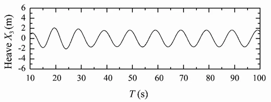
Fig.12 Heave response of S175 container ship. β=150˚, Fn=0.15, λ/L=0.9.

Fig.13 Rolling response of S175 container ship. β=150˚, Fn=0.15, λ/L=0.9.

Fig.14 Pitch response of S175 container ship.β=150˚, Fn=0.15, λ/L=0.9.
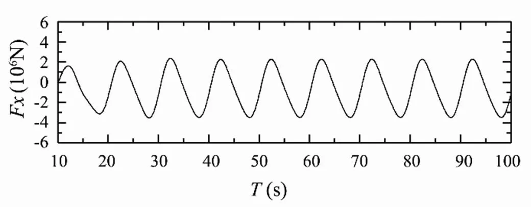
Fig.15 Longitudinal wave force of S175 container ship. β=150˚, Fn=0.15, λ/L=0.9.
Figs.16-18 present time histories of computed heave, roll and pitch motions of S175 container ship sailing in oblique bow waves (=150˚) with=0.25,/=1.0. Fig.19 pre- sents time history of computed longitudinal wave force on the ship under this condition.

Fig.16 Heave response of S175 container ship. β=150˚, Fn=0.25, λ/L=1.0.

Fig.17 Rolling response of S175 container ship. β=150˚, Fn=0.25, λ/L=1.0.

Fig.18 Pitch response of S175 container ship. β=150˚, Fn=0.25, λ/L=1.0.

Fig.19 Longitudinal wave force of S175 container ship. β=150˚, Fn=0.25, λ/L=1.0.
Figs.20 and 21 show the comparison between the cal- culated and experimental data of wave added resistance of S175 container ship sailing in oblique bow waves (=150˚) with=0.15 and 0.25.
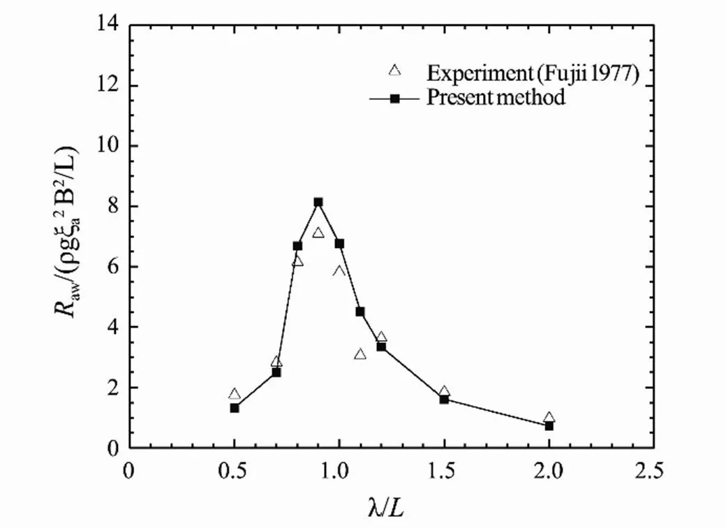
Fig.20 Wave added resistance of S175 container ship. β=150˚, Fn=0.15.
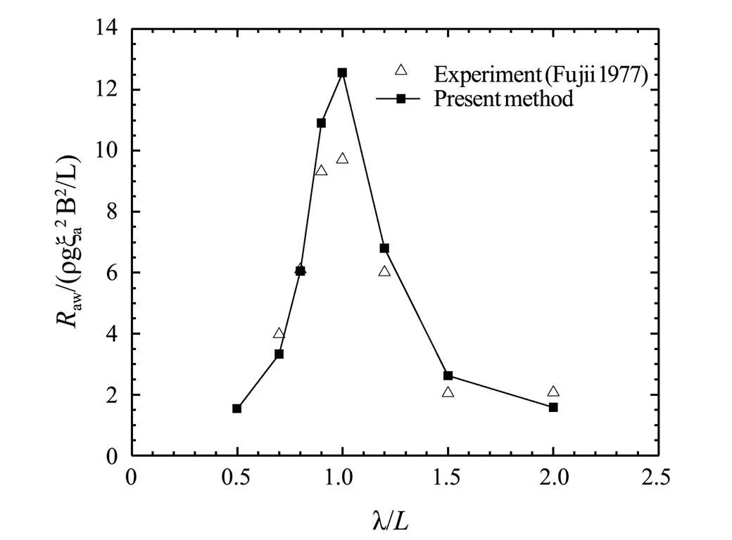
Fig.21 Wave added resistance of S175 container ship. β=150˚, Fn=0.25.
It can be seen that the wave added resistance in oblique waves calculated by this method are still in good agree- ment with the experimental values, and the accuracy meets the requirements. In the whole calculation range of/, the wave added resistance first increases and then decreases, and the peak values appear at/=0.9 and 1.0 respectively. The abscissas of the peak values are smaller than that in head waves, because the encounter wavelengthλin obli- que waves is larger than the wavelength, the calculation formula isλ=/cos(180˚−).
4.3 Motion Responses and Wave Added Resistance in Quartering Waves
Finally, the motion responses and wave added resistance of S175 container ship advancing in quartering waves (=30˚) with=0.15 and 0.25 are calculated. As in the case of oblique bow waves, the motions of the hull are calculated by solving the coupled motion equations of the three degrees of freedom (heave, roll and pitch), then the wave added resistance of the hull is obtained.
Figs.22–24 present time histories of computed heave, roll and pitch motions of S175 container ship sailing in quartering waves (=30˚) with=0.15,/=0.7. Fig.25 presents time history of computed longitudinal wave force on the ship under this condition.

Fig.22 Heave response of S175 container ship. β=30˚, Fn=0.15, λ/L=0.7.

Fig.23 Rolling response of S175 container ship. β=30˚, Fn=0.15, λ/L=0.7.
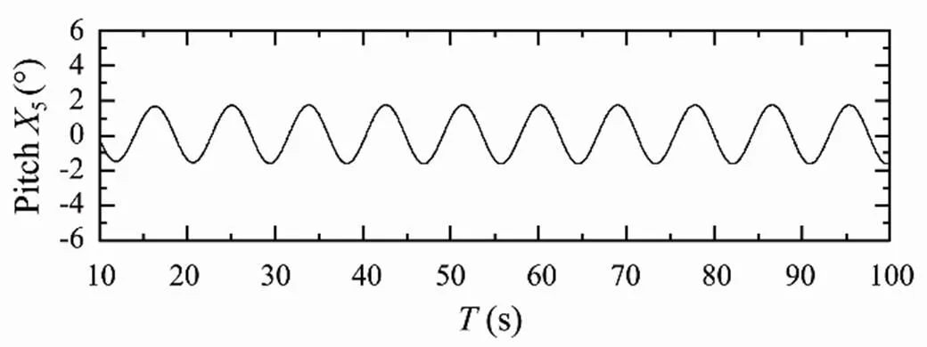
Fig.24 Pitch response of S175 container ship. β=30˚, Fn=0.15, λ/L=0.7.

Fig.25 Longitudinal wave force of S175 container ship. β=30˚, Fn=0.15, λ/L=0.7.

Fig.26 Heave response of S175 container ship. β=30˚, Fn=0.15, λ/L=0.7.

Fig.27 Rolling response of S175 container ship. β=30˚, Fn=0.15, λ/L=0.7.

Fig.28 Pitch response of S175 container ship. β=30˚, Fn=0.25, λ/L=0.7.

Fig.29 Longitudinal wave force of S175 container ship. β=30˚, Fn=0.25, λ/L=0.7.

Fig.30 Wave added resistance of S175 container ship. β=30˚, Fn=0.15.

Fig.31 Wave added resistance of S175 container ship. β=30˚, Fn=0.25.
Figs.30 and 31 show the comparison between the calcu- lated and experimental data of wave added resistance of S175 container ship sailing in quartering waves (=30˚) with=0.15 and 0.25. In the whole calculation range, the calculated values first increase and then decrease, which are in good agreement with the experimental data. Com- pared with the cases of=180˚ and=150˚, the wave added resistance with=30˚ is greatly reduced, and the differences between the extreme value zone and other zone are small. The calculation results show that the wave added resistance has little influence on the ship’s navigation in quartering waves, and the ship’s stability and maneuvering safety have become the important issues to be considered.
4.4 Discussion of Results
By comparing the calculated results with the experi- mental data under three wave directions, it is shown that the method proposed in this paper is feasible to calculate the motion responses and wave added resistance of ships in head and oblique waves, and the calculation accuracy meets the requirements of engineering application. With=180˚ and=150˚, the peak values of wave added resis- tance are prominent, and the calculation error at the peak values are relatively large. This is because this method is based on the potential flow theory without considering the viscosity of the fluid. When the ship moves violently, the computed values of the motion responses are too large, and the calculated radiation resistance will also be too large. Therefore, the calculated values of the wave added resis- tance are greater than the experimental data. When=30˚, the motion responses of the ship are small, so the wave added resistance of the ship are greatly reduced, and the curves of the force becomes relatively flat.In order to reduce the error, the introduction of viscosity correction coefficients can be considered, and the research will be carried out in future work.
When=180˚, the peak values of the calculation results with=0.15 and 0.25 appear at/=1.0 and 1.1 respec- tively. When=150˚, the corresponding extreme points appear at/=0.9 and 1.0 respectively. When=30˚, both of the two extreme points appear at/=0.7. It can be found that as the wave direction angle decreases, the/corresponding to extreme point of wave added resistance shifts to the left. This is because when the ship is sailing in oblique waves, with the decrease of the wave direction angle, the encounter wavelength of the hull gradually in- creases. Comparing the magnitudes of wave added resi- stance under different wave direction angles, it can be seen that the wave added resistance in head waves is the largest under the same conditions. With the decrease of the wave direction angle, the wave added resistance slightly decrea- ses in bow waves and greatly decreases in quartering waves. When=30˚, it can be seen from the time history curves of ship motion responses that although the mag- nitudes of the ship’s motion responses are significantly smaller, there are two peaks in a rolling cycle, which means the rolling motions become more complex. There- fore, the coupling characteristics of the ship’s motion responses are more obvious in quartering waves, and the complex motion responses are detrimental to the stability and safety of the ship.
5 Conclusions
Based on the potential flow theory and panel method, this paper proposes a method to calculate the ship motion responses and the wave added resistance, and then cal- culates the wave added resistance of S175 container ship sailing in head waves, bow waves and quartering waves. The comparison between the calculated results and the experimental data shows that the calculated wave added resistance of each wave direction angle are in good agreement with the experimental value. Because the potential flow theory ignores the viscosity of the fluid, the calculation errors will be relatively large in the interval of intense motion, but the overall calculation accuracy meets the requirements of engineering application.
In this paper, the wave added resistance of S175 con- tainer ship are calculated and analyzed under three wave directions. The results show that the wave added resistance is the largest in head waves under the same conditions. As the wave direction angle decreases, the wave added resi- stance gradually decreases. When the ship is sailing in quartering waves, the wave added resistance is greatly reduced, but the ship’s lateral and longitudinal coupled motions are more complex, which will bring adverse effects on the stability of the ship and the comfort of the personnel on board.
This paper proposes a fast method to calculate the motion responses and wave added resistance of ship in any wave direction, which can provide strong technical support for the development of high-performance new ship forms, optimization of ship hull lines, comprehensive performance evaluation of ships and practical navigation guidance.
Acknowledgements
The authors wish to acknowledge financial support from the National Natural Science Foundation of China (Nos. 51709246, 52171280, 51609220, U1806229).
Arribas, F. P., 2007. Some methods to obtain the added resistance of a ship advancing in waves., 34 (7): 946-955.
Boese, P.,1970. A simple method for the calculation of resistance increase of a ship in a seaway.,17: 86.
Chen, C., Liu, Y., He, Y., and Li, X., 2020. Numerical analysis of added resistance on an icebreaker in regular waves.,2: 1-13.
Chen, J. K.,Duan, W. Y.,Ma,S., and Liao,K.P., 2021. Time-domain tebem method for mean drift force and moment of ships with forward speed under the oblique seas., 26: 1001-1013.
Duan, W. Y., Li, J. D., Chen, J. K., and Ma, S., 2021. Time- domain TEBEM method for wave added resistance of ships with forward speed., 26: 174-189.
Faltinsen, O. M.,Minsaas, K. J., Liapis, N.,and Skjørdal, S.,1980. Prediction of resistance and propulsion of a ship in a seaway.. Tokyo, Japan, 505-529.
Fujii, H., and Takahashi, T., 1975. Experimental study on the resistance increase of a ship in regular oblique waves.. Otawa, Japan, 4pp.
Gerritsma, J., and Beukelman, W., 1972. Analysis of the resistance increase in waves of a fast cargo ship.,19(217): 285-293.
Grue, J., and Biberg, D.,1993. Wave forces on marine structures with small speed in water of restricted depth., 15 (3): 121-135.
Guo, B. J.,Steen, S., and Deng, G.B., 2012. Seakeeping prediction of KVLCC2 in head waves with RANS.,35: 56-67.
Hirota, K.,Matsumoto, K.,Takagishi, K.,Orihara, H., and Yoshida, H., 2004. Verification of Ax-bow effect based on full scale measurement.,241: 33-40.
Hong, L.,Zhu, R.,Miao, G., Fan, J., and Li, S.,2016. An investigation into added resistance of vessels advancing in waves., 123: 238-248.
Journee, J.M.J., 1992. Experiments and calculations on four Wigley hull forms. Faculty of Mechanical Engineering and Marine Technology, Delft University of Technology, Delft, Netherlands, Rep. 0909.
Kashiwagi, M.,Ikeda, T., and Sasakawa, T.,2010. Effects of forward speed of a ship on added resistance in waves., 20(3): 196-203.
Kim, Y.,Park, D. M.,Lee, J. H.,Lee, J.,Kim, B. S., and Yang, K. K., 2019. Numerical analysis and experimental validation of added resistance on ship in waves.,63 (4): 268-282.
Kuroda, M., Tsujimoto, M.,Sasaki, N.,Ohmatsu,S., and Takagi, K.,2012. Study on the bow shapes above the waterline in view of the poweringandgreenhouse gas emissions in actual seas., 226(1): 23-35.
Liu, S.,Papanikolaou, A., and Zaraphonitis, G.,2011. Prediction of added resistance of ships in waves.,38 (4): 641-650.
Maruo, H.,1960. The drift of a body floating on waves., 4 (3): 1-10.
Newman, J. N., 1967. The drift force and moment on ships inwaves., 11: 51-60.
Orihara, H., and Miyata, H.,2003. Evaluation of added resistance in regular incident waves by computational fluid dynamics motion simulation using an overlapping grid system.,8(2): 47-60.
Park, D.M.,Kim, Y.,Seo, M.G., and Lee, J.,2016. Study on added resistance of a tanker in head waves at different drafts.,111: 569-581.
Sadat-Hosseini, H.,Wu, P., Carrica, P.,Kim, H., Toda, Y., and Stern, F.,2013. CFD verification and validation of added resistance and motions of KVLCC2 with fixed and free surge in short and long head waves.,59: 240-273.
Salvensen, N., 1978. Added resistance of ships in waves.,2(1): 24-34,
Söding, H., Shigunov, V.,Schellin, T.E., and Moctar, O. E.,2014. A rankine panel method for added resistance of ships in waves., 136 (3): 15-21.
Stocker, R. M.,2016. Surge free added resistance tests in oblique wave headings for the KRISO container ship model.Master thesis. University of Iowa, Iowa.
Tezdogan, T., Demirel, Y. K., Kellett, P., Khorasanchi, M., Incecik, A., and Turan, O., 2015. Full-scale unsteady RANS CFD simulations of ship behaviour and performance in head seas due to slow steaming., 97: 186-206.
Valanto, P., and Hong, Y., 2015. Experimental investigation on ship wave added resistance in regular head, oblique, beam, and following waves.. Kona, USA, 19- 26.
Wang, X., Zhao, J., Liu, P., Cao, P., and Yu, T., 2019. Study on ship added resistance in regular head waves based on panel method.. Honolulu, Hawaii, USA, 2630- 2635.
Wang, X., Zhao, J., Zhang, H., Cao, P.,and Liu, P., 2020. Study on wave added resistance of a deep-V hybrid monohull based on panel method.,19(3): 601-608.
Yang, K. K., and Kim, Y., 2017. Numerical analysis of added resistance on blunt ships with different bow shapes in short waves., 22: 245- 258.
(Oceanic and Coastal Sea Research)
https://doi.org/10.1007/s11802-022-5074-3
ISSN 1672-5182, 2022 21 (3): 773-781
(May 18, 2021;
September 25, 2021;
October 13, 2021)
© Ocean University of China, Science Press and Springer-Verlag GmbH Germany 2022
Corresponding author. Tel: 0086-532-66781550 E-mail:zhangri@ouc.edu.cn
(Edited by Ji Dechun)
 Journal of Ocean University of China2022年3期
- Journal of Ocean University of China的其它文章
- Effect of Intertidal Elevation at Tsuyazaki Cove, Fukuoka,Japan on Survival Rate of Horseshoe Crab Tachypleus tridentatusEggs
- Asian Horseshoe Crab Bycatch in Intertidal Zones of the Northern Beibu Gulf: Suggestions for Conservation Management
- Experimental Investigation on the Interactions Between Dam-Break Flow and a Floating Box
- Variational Solution of Coral Reef Stability Due to Horizontal Wave Loading
- High Microplastic Contamination in Juvenile Tri-Spine Horseshoe Crabs: A Baseline Study of Nursery Habitats in Northern Beibu Gulf, China
- Influence of Autonomous Sailboat Dual-Wing Sail Interaction on Lift Coefficients