
A novel single wire indirect arc metal inert gas welding process operated in streaming mode
2022-07-26 08:18LiuAiguoZhaoJing
China Welding 2022年2期
Liu Aiguo , Zhao Jing
1. School of Materials Science and Engineering, Shenyang Ligong University, Shenyang 110159, China;2. Liaoning Horsen Automotive Parts Co. Ltd., Liaoyang 111000, China
Abstract Dilution of a pad weld must be limited to a certain critical level to improve its wear and/or corrosion properties. To do that, a novel single wire indirect arc metal inert gas welding process operated in streaming mode was realized. A metal inert gas welding torch, arranged perpendicular to a substrate in vertical position, is fixed with an auxiliary tungsten electrode horizontally. The arc is ignited between a wire through the torch and the auxiliary electrode. The substrate is not electrically connected. The welding current is set in the range of streaming mode. 304 stainless steel was pad welded on Q235 substrates in vertical position by this process. Microstructures were analyzed with optical microscope. Dilution ratios were measured with stereo light microscope and calculated. The results show that, after eliminating interference of the massive torch setup, the dilution ratio of the pad weld with optimized parameters is 5.07%, much less than that with a metal inert gas welding process, which is 26.46%. The pad weld is bonded to the substrate without defects. Microstructures of the pad weld consist of columnar austenite and ferrite between the columns. The dilution ratio increases with increasing welding current or welding velocity, and decreases with increasing distance to the substrate.
Key words pad welding, dilution ratio, indirect arc, streaming mode, vertical welding, metal inert gas welding
0 Introduction
Pad welding is widely used to improve wear and/or corrosion resistance of metal parts. Properties of the pad weld are determined by chemical compositions of the filler material, the welding process, the process parameters, and dilution ratio of the weld. The composition of the pad weld can be altered dramatically by incorporation of melted substrate,amount of which is determined by the welding process and the process parameters. Dilution of the pad weld will decrease wear and/or corrosion properties, so it must be limited to a certain critical level. Adamiec[1]has investigated pad welds of Inconel 625 alloy on water wall tubes to improve their wear and corrosion resistance. He has found that the Fe content in the pad welds should not exceed 10%. Exceeding a value of 10% may cause the formation of iron oxide Fe2O3on the surface of the pad weld, and Fe2O3has significantly lower adherence to the substrate than chromium oxide. Dilution ratios of welds produced by most commonly used welding processes, like manual metal arc(MMA) welding[2], metal inert gas (MIG) welding[3], submerged arc (SA) welding[4], are higher than 20%. These welding processes are not suitable for the pad welding on water wall tubes, or any other applications requiring low dilution of the welds. Low dilution can be realized by some processes, like laser cladding[5 – 6], plasma transferred arc(PTA) cladding[7 – 9], cold metal transfer (CMT) welding[10],hot wire gas tungsten arc welding (GTAW)[11]. But equipment for these processes is expensive, which restricts their widely application. An economical low dilution pad welding process has been the aim of many welding researchers[12 – 13].
Twin-wire indirect arc welding (TWIAW)[14], which is a process with high deposition efficiency and low dilution ratio, is especially suitable for wear and/or corrosion resistant surfacing. But it can only be operated in globular transfer mode to pad on horizontal substrates. In this paper, a novel single wire indirect arc metal inert gas (SWIAMIG) welding process operated in streaming mode is presented. The SWIAMIG process can be applied in pad welding with low dilution ratio in vertical position.
1 Materials and methods
1.1 Setup of the SWIAMIG process
A schematic diagram of the SWIAMIG process is shown in Fig. 1. The substrate fixed on a platform was arranged in vertical position, and it could move upward and downward to produce relative motion to the SWIAMIG torch. The SWIAMIG torch consisted of a MIG torch and a water-cooled auxiliary tungsten electrode. The MIG torch and the auxiliary tungsten electrode, fixed together with an angle of about 60° between axes of them, were arranged horizontally. The MIG torch was perpendicular to the substrate. The SWIAMIG torch was fixed on an oscillator which oscillated in horizontal direction parallel to the substrate. A filler wire was fed forward by a wire feeder through the MIG torch. The MIG torch was connected to the anode of a direct current (DC) power source, and the tungsten electrode was connected to the cathode. The DC power source was equipped with a high frequency generator.
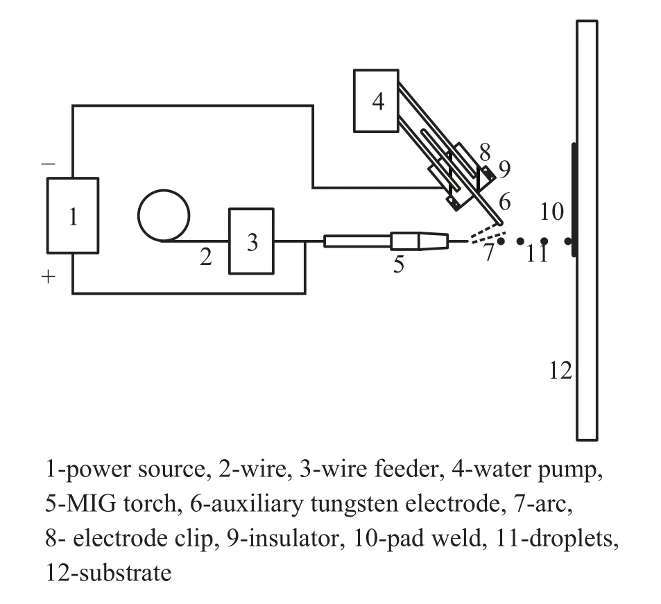
Fig.1 Schematic diagram of the SWIAMIG process
Before the welding process, the weld current was set in the range of streaming transfer mode. When the welding process started, a high frequency pulse was sent out from the high frequency generator, and an arc was ignited between the wire and the tungsten electrode, melting the wire. In the meantime, the wire was fed forward by the wire feeder. The tip of the wire melted and a droplet grew up on it. Driven by surface tension, electromagnetic force, arc plasma force, and gravity, the droplet detached from the wire tip and flied toward the substrate with very high temperature and very high velocity. When the droplet collided with the pre-cleaned substrate, it heated the substrate over melting point and bonded to it. Successively arrived droplets were combined to form a molten pool. With oscillation of the SWIAMIG torch and the substrate moving upward, the molten pool solidified continuously, and a pad weld formed. The substrate had been connected to neither anode nor cathode, so it is heated only by arc radiation and filler metal droplets. Less substrate melting is expected than with a traditional pad welding process, for example the MIG process. This is the key to low dilution ratio of the pad weld.
Combining a MIG torch with a TIG torch together has been proposed previously. But it has been used to measure the power input due to the combined action of arc radiation/convection and filler metal droplets[15], or as a wire melting method with an additional power source to improve efficiency of the TIG process[16], which is similar to the molten wire tungsten inert gas (MWTIG) welding process[17], rather than a dilution controlling way.
1.2 Experiments
304 stainless steel was pat welded on Q235 low carbon steel substrates with SWIAMIG process. The diameter of the 304 stainless steel wire was 1.2 mm. The size of the Q235 substrate was 200 mm × 100 mm × 4 mm. The Q235 substrate was fixed vertically on the platform. The distance of the tungsten electrode tip to the substrate was regarded as distance to substrate. Extension of the wire was 15 mm.Welding currents, welding velocities and distances to substrate were changed to investigate their influences on dilution ratio of the pad welds. The welding parameters for the SWIAMIG processes are shown in Table 1. Other parameters are as follows: arc voltage 22 V, oscillating speed 1 m/min, oscillating amplitude 9 mm, stop time at edges 0 s,wire extension 15 mm, and argon flow rate 12 L/s.
Table 1 Welding parameters
A specimen was welded with MIG process. Welding current of the MIG process is 210A, and welding speed is 2.7 mm/s.
The welded specimens were sectioned, polished and electrolytically etched with 40% nitric acid solution, and the microstructures in the pad welds were examined with optical microscope (OM).
The polished specimens were examined with stereo light microscope (SLM) to estimated dilution ratio of the welds.Images of the cross sections of the specimens were analyzed with Image Pro Plus, and the dilution ratio of the pad welds was calculated by
whereRis dilution ratio of the pad weld,S1is the area of the cross section of the pad weld, andS2is the area of the cross section of the pad weld below the upper surface line of the substrate.
2 Results and discussion
2.1 Microstructures of the pad weld
Microstructures of a typical SWIAMIG welded specimen with welding current 210 A, welding speed 2.7 mm/s,distance to substrate 25 mm, are shown in Fig. 2. The interface between the pad weld and the substrate is sound and without defects (Fig. 2 d). Planar crystals can be found next to fusion boundary. Fine columnar crystals grow upward from the planar crystals. The further away from the fusion boundary, the clearer columns become. The lighter columnar crystal is austenite, and between the columns is darker ferrite (Fig. 2 c).
From the middle part to the top part of the pad weld,more ferrite appears between the columnar austenite, and the austenite columns are broken (Fig. 2 b and 2 a). The ferrite content in Fig. 2 a is estimated to be 22.6%, higher than that in Fig. 2 c, which is 16.7%.
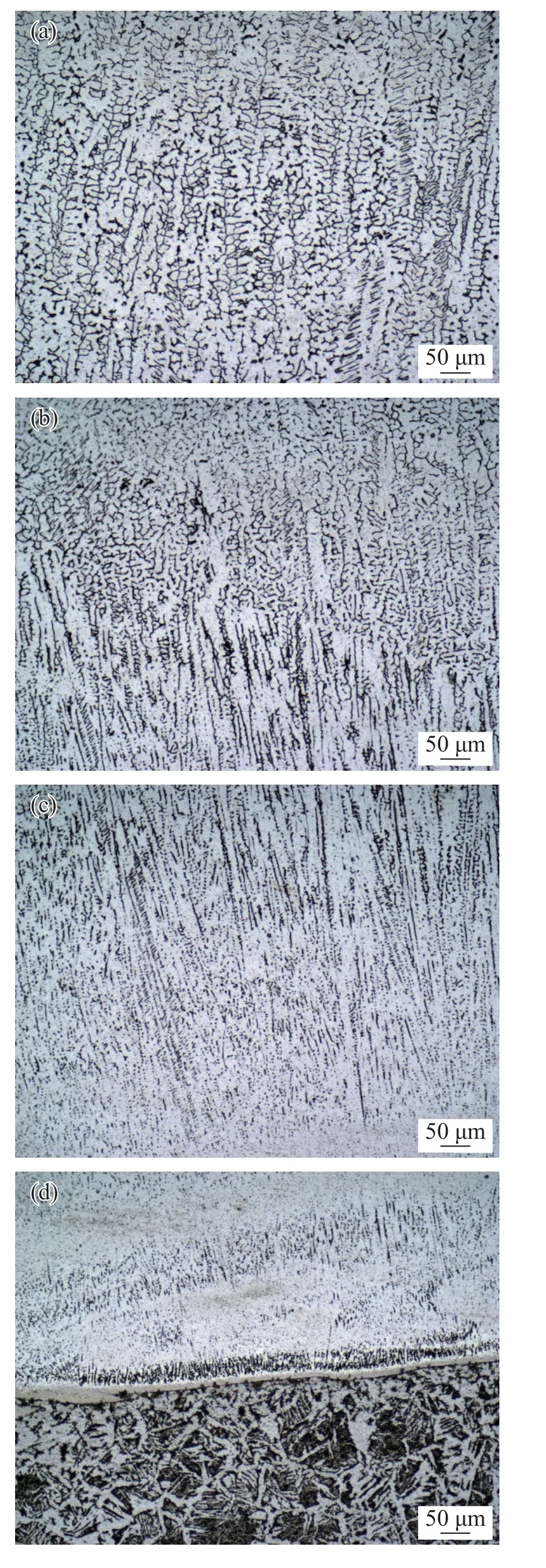
Fig.2 Microstructures of the pad weld (a) Upper part of the pad (b) Middle part of the pad (c) Lower part of the pad (d) Pad/substrate interface
2.2 Dilution ratio of the pad welds
Cross section of a typical SWIAMIG specimen is shown in Fig. 3 a. A MIG specimen is shown in Fig. 3 b for comparison. Dilution ratios of these two specimens are shown in Fig. 4. It can be found that, the SWIAMIG weld is bonded to the substrate with edges pinned deeper into it. If the substrate was bombarded by droplets evenly, it should melt uniformly. Obviously, the velocity of the torch varied a lot.The stopping time at edges was set to 0, but the prototype SWIAMIG torch setup is massive, and great inertia of it leads to extra stopping time at the end points of oscillation.So, the substrate under the edges of the pad weld is bombarded by extensive amount of droplets in a short time. Extra heat input into the substrate causes local deep melting. It is very obvious that the two edges of the pad weld contribute most part in the dilution ratio calculated. We believed that the dilution ratio of the pad weld with the edges included could not reveal the real characteristics of the SWIAMIG process. As extra melting of the substrate under the edges was caused by massive setup of the SWIAMIG torch, and could be eliminated in the future with an improved torch, dilution ratio of the pad weld with the edges trimmed off was calculated again. After eliminating interference of the massive torch setup, the dilution ratio of the SWIAMIG pad weld with optimized parameters is 5.07%.

Fig.3 Cross sections of a typical SWIAMIG specimen and a MIG specimen (a) SWIAMIG specimen (b) MIG specimen
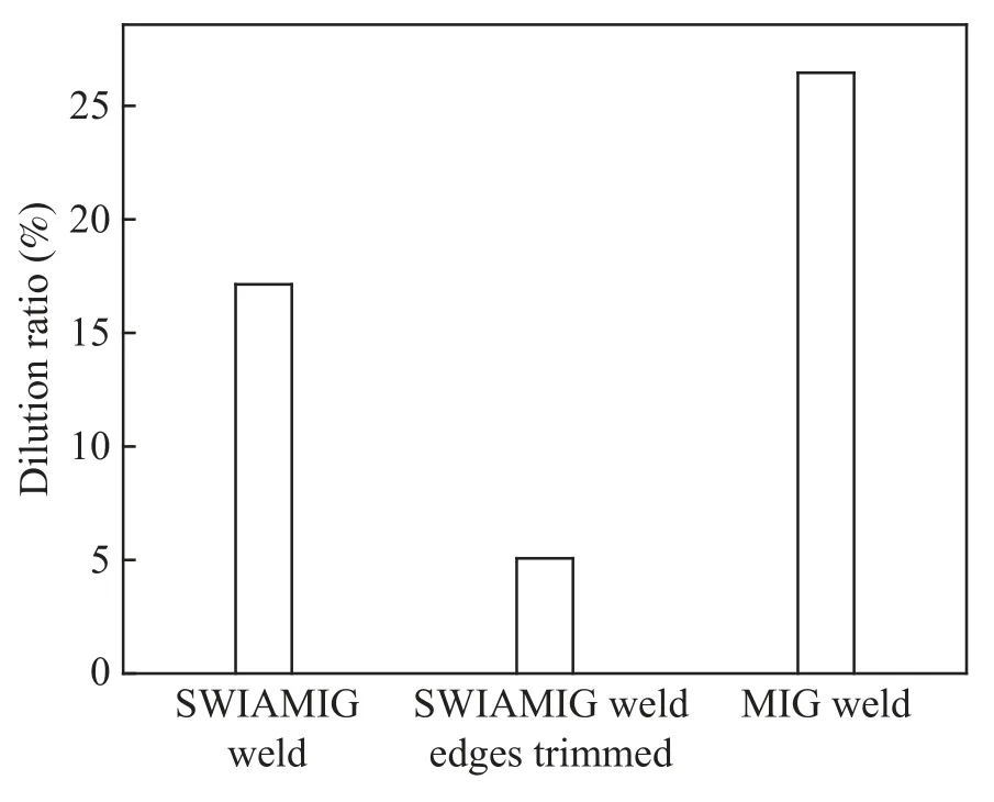
Fig.4 Dilution ratios of the SWIAMIG specimen and the MIG specimen
The width of the MIG weld is larger than that of the SWIAMIG pad weld, and cannot be arranged in a single view of the SLM. So Fig. 3 b consists of two images combined together. Dilution ratio of MIG weld is 26.46%, much higher than that of the SWIAMIG.
2.3 Influences of welding parameters on dilution ratio of the pad welds
Fig. 5 shows influence of welding currents on dilution ratio. When the current is less than 190 A, a steady stream cannot be obtained. When the current is 190 A, a steady stream of droplets can be projected onto the surface of the substrate, and a pad weld forms. The heat input is relatively low and morphology of the weld is not sound or good.Some holes can be found on the surface. Most part of the substrate does not melt. Some defects can be found on the interface. Dilution ratio of the pad weld is as low as 4.35%.The only melted substrate part is below the edge of the pad weld. When the edges were trimmed, the dilution ratio calculated was 0. This suggests that the pad weld is not bonded to the substrate well. When the current increases to 200 A and 210 A, appearances of the pad welds are sound and are bonded to the substrate well. The dilution ratio increases with increasing welding current. When the welding current increases, more radiation from the arc is conveyed to the substrate, and the droplets are heated to higher temperature. Much substrate melts, so dilution ratio increases.When the welding current increases further, morphology of the pad weld gets worse.
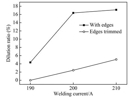
Fig.5 Influence of welding currents on dilution ratio
Fig. 6 shows influence of welding velocities on dilution ratio. With welding velocity increasing, thickness of the welds decreases. This means decreasing ofS1in Eq. (1). In the meantime, the increased welding velocity means that fewer droplets bombard the substrate per second. So less substrate melts, andS2decreases. ThatS1andS2decrease simultaneously results in dilution of the welds first increasing and then decreasing. However, after the edges trimmed,the dilution ratio of the specimen with welding velocity 3.1 mm/s is higher than that of the specimen with welding velocity 2.7 mm/s. Increasing welding velocity means that the torch spends less time at the edges, for it moves forward more. Heat input distributes more uniformly. So the substrate melts less under the edges, and more in the middle. The substrate melts more uniformly with welding speed of 3.1 mm/s, but the surface morphology is not good.
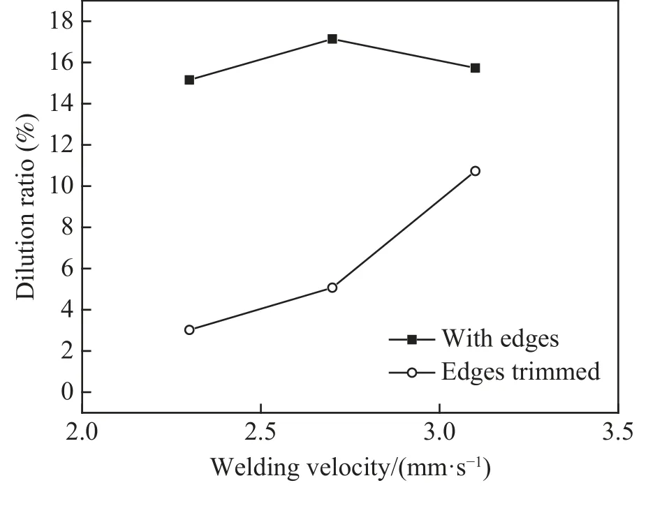
Fig.6 Influence of welding velocities on dilution ratio
Fig. 7 shows influence of distances to the substrate on dilution ratio. Dilution ratio decreases with distance to the substrate increasing. With distances to the substrate increasing, less heat radiation from the arc is conveyed to the substrate, and the droplets lose more heat in the process of flying to the substrate. So the substrate melts less.

Fig.7 Influence of distances to the substrate on dilution ratio
3 Conclusions
(1) Dilution ratio much lower than MIG pad welding can be obtained using SWIAMIG process. After eliminating interference of the massive torch setup, the dilution ratio of the SWIAMIG pad weld with optimized parameters is 5.07%.
(2) The pad weld is bonded to the substrate without defects. Microstructures of the pad weld consist of columnar austenite and ferrite between the columns.
(3) The dilution ratio of the pad welds increases with increasing welding current or welding velocity, and decreases with increasing distance to the substrate.
The massive setup of the prototype SWIAMIG torch has great influence on the experiment results, and has obstructed further investigation of the process. It must be improved in the coming work. We believe that with a light torch, the SWIAMIG process will do great in vertical position pad welding.
- China Welding的其它文章
- The study of arc behavior with different content of copper vapor in GTAW
- Research on stretching flame correction technology of aluminum alloy ship frame skin welding structure
- Application of silver nanoparticles in electrically conductive adhesives with silver micro flakes
- Groove modeling and digital simulation for intersecting structures of circular tubes based on coplanarity of vectors
- A review of welding residual stress test methods
- Ceramic-copper substrate technology introduction