
A review of welding residual stress test methods
2022-07-26 08:18GanShimingLiuHuayingZhaiZhipingHanYongquan
China Welding 2022年2期
Gan Shiming , Liu Huaying , Zhai Zhiping , Han Yongquan
1. School of Mechanical Engineering, Inner Mongolia University of Technology, Hohhot 010051, China;2. School of Materials Science and Engineering, Inner Mongolia University of Technology, Hohhot 010051, China;3. Key Laboratory of electromechanical control of Inner Mongolia Autonomous Region, Hohhot 010051, China
Abstract Due to local uneven heating during the welding process, the residual stress of the structure after welding affects the reliability of it. In order to ensure the reliability, it is of great significance to test the residual stress distribution of the welded joint. It has always been the focus to find a simple and feasible method for residual stress testing to quickly and accurately obtain the residual stress distribution of welded joints. The mechanical measurement method has high measurement accuracy, convenient and easy operation, but it will cause certain damage to the components. Physical measurement method can avoid damage to components, but its test cost is usually high, and its measurement accuracy can also be affected by the material microstructure characteristics of welded components. Based on the advantages and disadvantages of these two residual stress test methods, a modal test method is proposed. This method is a non-destructive measurement method.Based on the mathematical relationship between the residual stress of the welded structure and the natural frequency (mathematical model),the natural frequency is measured through the modal test to calculate the residual stress quickly. However, it is difficult to establish a mathematical model with this method, and it is not suitable for realization.
Key words welding residual stress, mechanical measurement method, physical measurement method, modal test method
0 Introduction
Welding can achieve efficient joint between metal components. However, the heat input during welding is often local uneven heating. The uneven heat input affects the metal movement around the heat source through the internal and external constraints constituted by material factors,manufacturing factors, and structural factors, and finally forms welding stress. Welding residual stress will have an adverse effect on the static load strength, fatigue strength,service life, and stress corrosion cracking resistance, rigidity and dimensional stability of the welded structure[1]. In order to ensure the reliability of welded joints, it is often necessary to measure and master the distribution of residual stress in welded joints.
How to quickly and accurately obtain the residual stress distribution of welded joints has always been the focus. The research of traditional residual stress measurement methods began in the 1930s, and has developed a variety of measurement methods. In summary, they can be divided into two categories: mechanical measurement methods and physical measurement methods[2]. Mechanical measurement methods mainly include hole-drilling method, contour method,ring-cutting method, block-cutting method, indentation method and layer-by-layer milling method. They mainly use mechanical methods to destroy components with residual stress in the measurement part to make the residual stress release and realize the measurement. The physical measurement methods mainly include X-ray diffraction method,neutron diffraction method, ultrasonic method, and magnetic measurement method. They mainly use the physical properties of materials to achieve non-destructive measurement of components. Analyzing and comparing the advantages and disadvantages of mechanical and physical measurement methods, the researcher also proposed a modal test method. The residual stress test method provides convenience for the analysis and research of welding residual stress.By analyzing the advantages and disadvantages of the existing residual stress test methods, it can lay a foundation for accurately, quickly and non-destructively to obtain the residual stress distribution characteristics of the welded structure.
1 Mechanical measurement method
1.1 Hole-drilling method
Hole-drilling method is the most widely used mechanical measurement method. It was first proposed by German J Mathar in 1934, and then developed and improved by Soete et al. to form a theoretical system. It has been incorporated into the standard system by American ASTM Association,European Union and China. As shown in Fig. 1[3], the principle is to drill a small hole at the point to be measured on the surface of the component, measure the release strain through a resistance strain gauge, and calculate the residual stress according to the stress-strain relationship as follows:
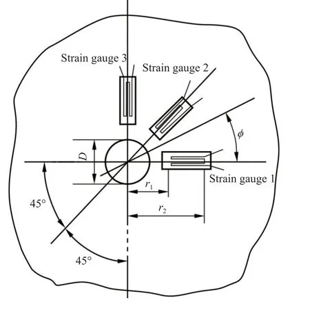
Fig.1 Schematic diagram of hole-drilling method measurement principle
where,σ1andσ2are the residual principal stress;ε1,ε2andε3are the strain values in three directions measured by the strain gauges 1, 2 and 3;AandBare the strain release coefficients;ϕis the angle between the principal stressσ1and the strain gauge 1.
This method is convenient and easy to operate, less destructive to components, and has higher measurement accuracy and cheaper equipment. The shortcomings are that it needs to drill holes on the surface of the tested part to damage the components. The drilling process often causes material damage and yield problems, which affect the measurement effect. After continuous research and development, the hole-drilling method has been combined with computer technology, optical technology and network technology to make the measurement process more refined and intelligent,and improve the measurement efficiency of residual stress to a great extent. Dai et al.[4]proposed to use displacement information measured by moiré interferometry instead of strain information measured by strain gauges to determine residual stress. Therefore, a portable moiré interferometry drilling system that can measure residual stress on-site is developed, and the residual stress of aluminum alloy laser welded joints was measured. Researchers have analyzed and estimated error factors such as drilling eccentricity, paste angle deviation of strain gauge, plastic deformation of the hole edge, drilling diameter and drilling depth, and sticking size of strain gauge through simulation and experimentation[5 – 8]. The measurement error has been effectively controlled, and the accuracy of the residual stress measurement by the hole-drilling method is improved.
Presently, the hole-drilling method has a complete theoretical system and has become the most commonly used method for measuring residual stress. Combining it with numerical simulation methods can more accurately analyze the residual stress distribution in welded joints. Ma et al.[9]proposed a reverse drilling method of inner wall pasting strain gauge and outer wall drilling and obtained a better measurement effect in view of the difficult problem of the stress test on the inner wall of the tubular workpiece. Vasileiou et al.[10]used the incremental deep hole drilling method to measure the arc and electron beam welding residual stress of 130 mm thick SA508 steel reactor pressure vessel. Sun et al.[11]used a combination of hole-drilling method and numerical simulation to analyze the distribution of residual stresses in the axial, circumferential and radial directions of the welded joints of high-density polyethylene pipes. Combining the numerical simulation, Han et al.[12]used the holedrilling method to investigate the residual stress distribution of keyhole gas tungsten arc welding (K-TIG) of Q345 low alloy steel plates. Pu et al.[13]investigated the residual stress in the repair weld process of P92 steel plates through the hole-drilling method and numerical simulation, and analyzed influence of the repair length on the residual stress in P92 steel repair welds. Generally, in addition to the destructive shortcomings and the lack of applicability for low level stress, the technology of hole-drilling method is mature and has high measurement accuracy, and has been widely used to verify the reliability of some new measurement methods.
1.2 Contour method
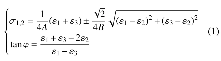
The contour method is a cutting mechanical destruction method, as shown in Fig. 2[14]. The principle is to completely cut the sample into two halves along a certain section. Due to the stress release, the cutting surface profile is deformed. According to the superposition principle in elastic mechanics, the external force is applied to restore the deformed cutting surface to the plane state before cutting. The resulting stress state is equivalent to the initial residual stress on the plane before cutting. This method was first proposed by Prime[14]and measured the two-dimensional residual stress distribution on a certain section. Zhang et al.[15]used the contour method to measure the residual stress of 2024 aluminum alloy VPPA welding. Xie et al.[16]concluded that the profile method can only measure the normal stress perpendicular to the direction of the cutting surface,and has a good measurement effect on the residual stress field inside the material, but the measurement error of the residual stress on the surface is relatively large. In the testing process of contour method, the plastic deformation error caused by cutting and the fitting error caused by fitting contour surface can affect the testing accuracy. In order to improve the test accuracy of counter method, Toparli et al.[17]optimized the cutting parameters, proposed a new criterion of optimal fitting node spacing, and obtained reliable test results of near surface. Ahmad et al.[18]corrected the error caused by cutting through setting additional surface layer, and effectively reduced the irregularity of test results of near surface.
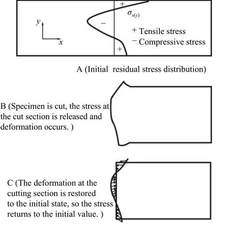
Fig.2 Schematic diagram of contour method measurement principle
In short, the contour method will cause certain damage to the structure by cutting, and has higher measurement accuracy of the residual stress field in the material, but the measurement accuracy of the residual stress on the surface is relatively low. In future, on the basis of correcting the plastic deformation error caused by cutting, a more effective contour fitting method is established, and high-precision residual stress distribution results can be obtained by combining X-ray diffraction method.
1.3 Ring-cutting and block-cutting method
Ring-cutting method and block-cutting method are mainly used in the measurement of residual stress of welded pipe[19]. Ring-cutting method is to cut a certain length of pipe from the welded pipe, then cut it along the axial direction, and calculate the residual stress by the deformations of the ring circumferentially, axially and radially. The measurement result reflects the average stress in the entire thickness direction in the width of the cutting ring. Xiao[20]gave a method for measuring the axial residual stress of aluminum-magnesium alloy steel pipes with a cutting length of 70 mm, which can measure the average axial residual stress of aluminum-magnesium alloy steel welded pipes. The block-cutting method is similar to the ring-cutting method.In the residual stress measurement of the welded pipe, the residual stress is calculated by the strain released by the sample block cut from the welded pipe. The measurement result reflects the average value of stress release in the entire thickness direction in the range of the block-cutting.Xiong et al.[21]tested the average residual stress of largediameter thick-walled X80 steel spiral seam submerged arc welded pipe and longitudinal seam arc welded pipe using the ring-cutting method. The residual stress estimated by the ring-cutting method is close to the measured value by the hole-drilling method, and the average residual stress of the spiral submerged arc welded pipe is larger than that of the longitudinal submerged arc welded pipe. The ring-cutting method and the block-cutting method are mainly suitable for tubular welded structures, and they will also cause damage to the structure.
1.4 Indentation method
The indentation method is a micro-mechanical destruction method, and its measurement principle is shown in Fig. 3 and Eq.(2). A spherical indenter is used to indent the surface of the sample to produce a spherical crown shape of a certain size, and the superposition of the formed applied stress field and the residual stress field causes a strain increase. The residual stress value is obtained by the relationship curve between strain increment and elastic strain precalibrated in advance[22].
Fig.3 Schematic diagram of indentation measurement principle

whereσxandσyare the residual principal stress;Eis the elastic modulus;ʋis the poisson ratio;εexandεeyare the elastic strain.
The research of indentation method to measure residual stress originated from the traditional Rockwell hardness test or Vickers hardness test. The residual stress value is mainly calculated by the influence of residual stress on the hardness or the area of residual indentation[23 – 24]. Huang et al.[25]used the indentation method to measure the residual stress of 2 219 aluminum alloy with variable polarity TIG welding, and obtained the measurement results consistent with the hole-drilling method. Shen[26]obtained the relationship between the indentation morphology variation and the residual stress by studying the difference of the indentation surface morphology, and gave a residual stress test method based on the indentation bulge, so that the indentation method can be directly applied in engineering testing. With the continuous development of indentation technology, nano-indentation method and in-situ high temperature indentation method have emerged to measure the welding residual stress on the surface of some thin film materials.
In the process of measuring residual stress, the advantage of indentation method is mainly reflected in the small damage to the component, because the indentation depth is an average response, it can only measure the average residual stress value. Besides, the excessive plastic zone should be avoided, which seriously affects the accuracy of the test results, and the reasonable functional relationship between strain increment and residual stress should be established,so as to complete the measurement of residual stress on the structural surface efficiently and accurately.
1.5 Layer-by-layer milling method
The principle of the layer-by-layer milling method is to peel off the specimen surface by milling, electrolytic corrosion, electric spark erosion or grinding and polishing, so as to release the residual stress on the surface. The resistance strain gauge is used to measure the deformation of the remaining part of the specimen after peeling off the layer to obtain the released stress. This method is mainly used to measure the distribution of residual stress in the thickness direction of thick plate specimens. Zou et al.[27]used a layerby-layer milling method to measure the residual stress in the weld zone of a 45 mm thick steel plate, and obtained its distribution along the weld thickness. When using the layerby-layer milling method to measure the residual stress in the whole thickness direction of isotropic materials and composite samples, Salehi et al.[28]gave an appropriate safety distance parameter for repeated slitting; this eliminated the influence of previous cutting and ensured the accuracy of measurement. This method can obtain the residual stress at different depth positions of the welded structure, but the peeling process such as milling is not easy to operate, which limits its application.
2 Physical measurement method
2.1 X-ray diffraction method
Based on the theory of elasticity and X-ray crystallography, X-ray diffraction method was proposed by Russian scholars in 1929. After continuous research and development, it has been successively incorporated into the standard system by American ASTM Association, European Union and China. It has become the most widely used non-destructive stress measurement method. The principle of Xray diffraction method is that stress changes the lattice constant of the component material. By measuring the movement of diffraction peak position of the component sample,the amount of change in the crystal plane spacing in a certain direction relative to the unstressed state in the material is calculated, and the strain is obtained, and then converted into stress value[29]. Its principle is shown in Fig. 4[30].ψis the angle between the normal of the diffraction surface and the normal of the sample surface, and 2θis the angle of diffraction. According to the one-to-one correspondence between the X-ray incident angle and the diffraction angle,when measuring, at least four groups of different incident angles are selected to measure the corresponding diffraction angle, with sin2ѱis the abscissa and the diffraction angle is the ordinate. A straight line is fitted to obtain the slope and intercept of itself, so as to calculate the residual stress value of the point to be measured in a given direction,We have
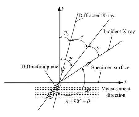
Fig.4 X -ray diffraction principle
where,Kis stress constant,Eis the elastic modulus of the sample,υis the poisson ratio of the sample,θ0is the Bragg angle of the diffraction peak of the sample without stress,and 2θis the diffraction angle at different incident angles.
The X-ray diffraction method will not damage the components. The continuous popularization of the X-ray stress meter makes the X-ray diffraction method widely used in the measurement of the residual stress of welded structures.Lu et al.[31]used X-ray diffraction method to measure the residual stress of stainless steel welding specimens, to compare and analyze the measurement results with the holedrilling method, and gave the application validity and scope of the X-ray diffraction method. Ganguly et al.[32]used the synchrotron radiation X-ray method to quickly measure the two-dimensional residual stress of VPPA weldments. Lin et al.[33]used cosαX-ray diffraction method to measure and determine the residual stress distribution of welded joints with geometrically asymmetric thin steel plates. With the help of X-ray method, Nikulin et al.[34]has revealed the degree of inhomogeneity of residual stresses in hard-facing specimens made with flux-cored wire and coated electrode in air and underwater.
The penetration of X-ray diffraction method is limited,so that its measuring depth is only 30−40 μm. Therefore, the X-ray stress meter is generally used to measure the two-dimensional residual stress on the surface of the component.On the basis of two-dimensional residual stress measurement, according to the three-dimensional residual stress tomographic scanning measurement method proposed by Chen et al.[35], and some special three-dimensional residual stress analysis and calculation software, three-dimensional stress measurement of weldments and other components is gradually realized. However, the tomographic scanning measurement method needs to slice layers successively,which is destructive to the test piece, and essentially changes the X-ray diffraction method from a non-destructive measurement to a destructive measurement.
As the portable X-ray diffractometer has been relatively mature, the application of this method in the field of engineering has been further popularized. The X-ray diffraction method can measure the surface residual stress of the welded structure non-destructively and quickly, but cannot directly measure the residual stress inside the structure.Moreover, the measurement accuracy of this method is affected by the material structure characteristics of the specimen. At the same time, the test results are also greatly affected by the surface quality. If the surface quality is not handled properly, it is difficult to obtain the ideal residual stress distribution. For most welded structures, the weld surface is uneven, so it is not suitable for X-ray method to measure the residual stress on the weld centerline.
2.2 Neutron diffraction method
The measurement principle of neutron diffraction method is similar to that of X-ray diffraction method[36 – 37], and its research originated in the 1980s. Because neutron is used as diffraction source, the ability of penetration is stronger than that of X-ray, and the measurement depth can reach 30−40 mm. At first, the equipment of neutron diffraction method was expensive. The United States and Europe paid more attention to the research of neutron diffraction method, while there was less research in China. Hayashi et al.[38]used neutron diffraction method, X-ray diffraction method and strain gauge method to measure the residual stress of carbon steel welded pipes, compared the measurement results and pointed out that neutron diffraction method is the most effective method to measure the internal stress of the structure. Meysam et al.[39]used neutron diffraction method to measure the residual stress distribution of AA7075 aluminum alloy friction stir welded joints, and obtained measurement results consistent with that of the nanoindentation method. Wan et al.[40]used the neutron diffraction method to measure the residual stress distribution in the thickness direction of the duplex stainless steel multi-pass welded joint,and found that the elastic residual stress of the austenite phase is larger than that of the ferrite phase. Presently,China has made certain progress in the research of neutron diffraction method. The Institute of Atomic Energy has developed the China Advanced Research Reactor (CARR)Neutron Residual Stress Spectrometer. Liu et al.[41]designed a calibration experiment and software for this neutron residual stress meter, so that it can measure the residual stress inside the workpiece more accurately. Shen et al.[42]used neutron diffraction method to measure the residual stress of additive manufacturing produced components, and measured the residual stress of twin wire-arc additive manufacturing (T-WAAM) produced Ti48Al titanium aluminide components.
The measurement depth of the neutron diffraction method is deeper than that of the X-ray diffraction method, and it is able to test the residual stress inside welded components.However, there are some disadvantages to use neutron diffraction method to measure residual stress. The measurement accuracy is still limited by the material microstructure and neutron penetration ability. The equipment of neutron diffraction is generally more expensive, which greatly limits the application. Besides, neutron diffraction can not accurately measure the distribution of residual stress on the surface and near surface of the welded joint.
2.3 Ultrasonic method
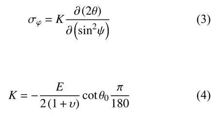
The ultrasonic method uses the acoustic birefringence phenomenon in materials with stress and the relationship between ultrasonic wave velocity and stress to measure residual stress on the basis of elastic theory[43]. When the ultrasonic wave is incident into the component at a certain angle, it will produce a 90° refraction angle in the component and a refracted longitudinal wave propagating on the surface. Under the influence of residual stress, the velocity of ultrasonic wave will change after entering the material.The measurement process is shown in Fig. 5. The distance between the ultrasonic incident probe and the receiving probe is a fixed value, according to the linear relationship between the velocity of ultrasonic wave and stress, the residual stress in the material can be calculated as
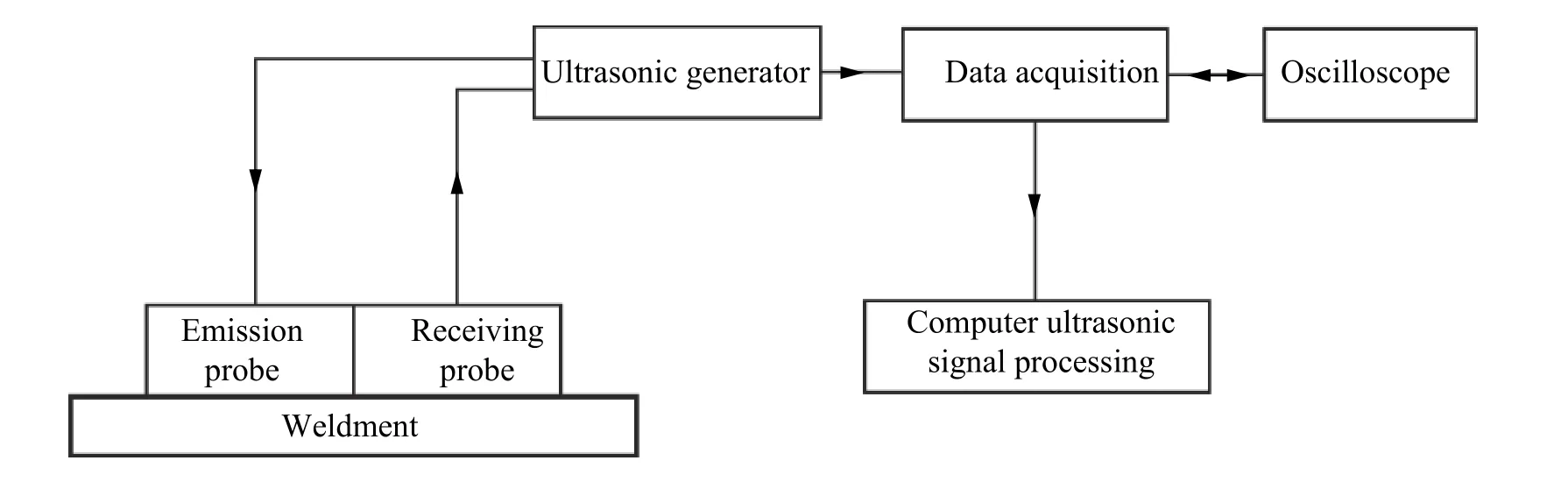
Fig.5 Process of residual stress measurement by ultrasonic method
where,Kis stress constant;tis the propagation time of the LCR wave in the sample under stressed state;t0is the propagation time of the LCR wave in the sample under unstressed state; Δtis the time differences of the sample under stressed and unstressed state.
In recent years, the ultrasonic method has been fully experimental research and engineering application. Early Polish scholars successfully measured the stress generated during the manufacture of steel rolls and the stress generated by thermal action after the steel rolls were installed on the subgrade by ultrasonic method. Xu et al.[44]used the ultrasonic method to measure the plane two-way residual stress on the aluminum alloy plate welding test piece of the spacecraft,and obtained approximately the same results as the strain gauge measurement. Wang et al.[45]measured the surface residual stress of aluminum alloy welded plates by ultrasonic method on the basis of considering the weak anisotropy of metal materials.
Ultrasonic method is a non-destructive measurement method, and the measurement depth is deeper than X-ray diffraction method. In some special cases, the residual stress inside the specimen can be measured. However, the propagation of ultrasonic waves is greatly affected by the medium and environmental noise. It is necessary to use a probe with high resolution and strong anti-interference ability to measure the change of the waveform, which makes the measurement process more complicated. Considering the coupling conditions between the probe and the measuring surface, Liu et al.[46]improved the traditional single transmitter and single receiver detection structure to single transmitter and double receiver structure, which effectively reduced the deformation and attenuation of ultrasonic signal, and improved the test accuracy of ultrasonic method.
In short, ultrasonic method has become an important means of non-destructive testing of residual stress, but there are still some factors affecting its application in welded structure. Inside the material, the response of ultrasonic velocity to stress is relatively insensitive. The microstructure of different areas in the welded joint will cause birefringence effect, which is easy to cause significant fluctuation of ultrasonic velocity. The size of ultrasonic transmitting and receiving probes is large, and the spatial separation rate is low, so it is impossible to obtain the change of stress gradient in weld and heat affected area of welded joint.
2.4 Magnetic measurement method
The magnetic measurement method uses the magnetostrictive effect to measure the residual stress, mainly including the magnetic memory detection method, the magnetic stress method, the Barkhausen effect method and the magnetic and acoustic emission method, among which the Barkhausen effect method is relatively mature. The measuring depth can reach several millimeters with no radiation and fast speed, and it is suitable for on-site measurement. In recent years, researchers have realized the measurement of welding residual stress using magnetic measurement. Jiang et al.[47]used the magnetic measurement method to measure the residual stress distribution of T-welded specimens.Liu[48]used the magnetic measurement method to measure the welding residual stress of the steel structure bridge.Based on the metal magnetic memory (MMM) method,Sergey et al.[49]investigated the stress state of the welding specimens before and after post weld heat treatment, and found that it can quickly detect the stress state inhomogeneity zones of welded joints by the MMM method. However,the magnetic measurement method has poor reliability and accuracy, consumes energy, and is only suitable for ferromagnetic materials. Further more, it will cause residual magnetism to the components after measurement, which may make the environment polluted.
3 Modal test method
Based on the advantages and disadvantages of mechanical method measurement and physical measurement methods, modal test method is gradually proposed. The modal test method can be regarded as a non-destructive residual stress measurement method. Its core idea is to establish the mathematical relationship between residual stress and natural frequency (mathematical modeling). Using the established mathematical relationship and measuring the natural frequency through the modal test, the residual stress can be quickly calculated. When there is residual stress in the component, the elastic modulus of the component will change,which will affect its vibration response characteristics and change the natural frequency. Therefore, the residual stress will affect the natural frequency of the component. Kaldas and Almeida et al. conducted earlier studies on the influence of residual stress on natural frequencies through vibration theory[50 – 51]. Vieira compared and analyzed the vibration frequency response function of SAE 1 020 carbon steel in the two states of annealing (without residual stress) and coating electrode welding through modal tests, as shown in Fig. 6[52]. It is found that the welding residual stress will shift the peak of the frequency response function, that is, affect the natural frequency of the component. Abdelmoula et al.[53]analyzed the vibration characteristics of AA6061-T6 aluminum alloy friction stir welded plate through finite element simulation, and found that the existence of residual stress did affect the natural frequency of the plate. Gao et al.[54]systematically analyzed the influence of welding residual stress on the natural frequency in rectangular thin plate. Hu et al.[55]analyzed the influence of the quenching residual stress of 7 075 aluminum alloy thick plate on its natural frequency, and found that when the size and density of the plate were determined, the natural frequency was mainly affected by the distribution of the residual stress field. Chen et al.[56]analyzed the influence of different distribution forms of welding residual stress on the natural frequency of plate structure by means of numerical calculation.
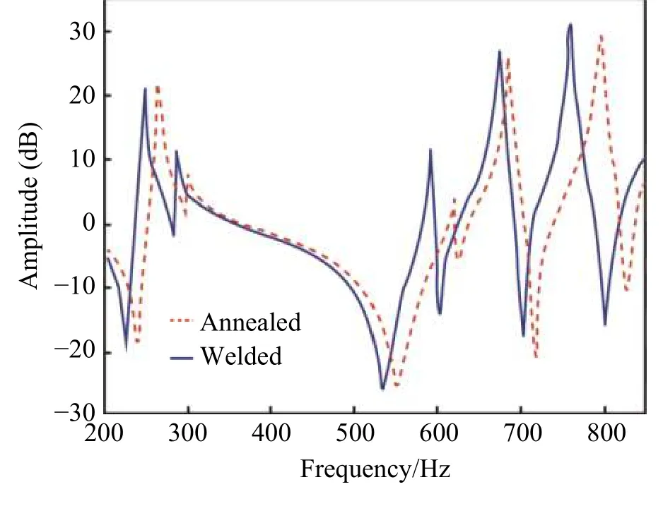
Fig.6 Influence of welding residual stress on frequency response function
On the basis of studying the influence of residual stress on natural frequency, the relationship between welding residual stress and natural frequency has been also successively studied. Vieira et al.[57]used the classical thin plate vibration theory and Airy stress function model to give the relationship between the surface residual stress and the natural frequency of the rectangular thin steel plate after TIG welding. Li et al.[58]analyzed the relationship between the natural frequency of beam cast iron and its residual stress from the perspective of modal theory and modal test. Guo et al.[59]used modal tests and data fitting methods to fit the relationship between the residual stress and natural frequency of the drive axle housing under different modalities for the complicated case of measurement of the welding residual stress of the drive axle housing. Gao et al.[60 – 61]analyzed the influence of welding residual stress on the natural frequency in a rectangular thin plate, and gave the general distribution characteristics of the longitudinal residual stressσxand the transverse residual stressσyexisting in the rectangular thin plate, as shown in Fig. 7[54]and Fig. 8[54]. The corresponding mathematical models of residual stress were established as follows:
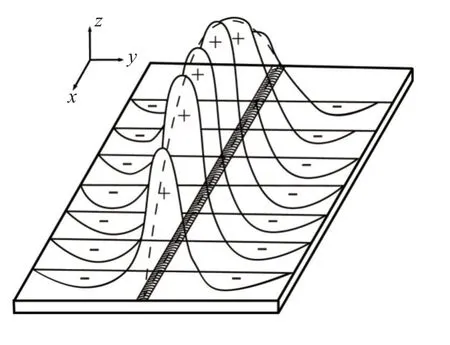
Fig.7 Distribution of longitudinal residual stress σx
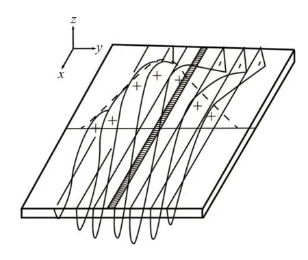
Fig.8 Distribution of transverse residual stress σy
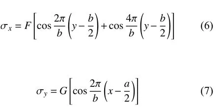
where,FandGare the amplitudes, andaandbare the length and width of the welded plate, respectively.σxis described as a trigonometric function with respect toyin the width direction of the rectangular plate, andσyis described as a trigonometric function with respect toxin the length direction of the rectangular plate. Under the boundary condition of simply supported on four sides, the first three natural frequencies of welded thin plate were theoretically calculated, and the calculated results were relatively close to the natural frequencies obtained from the modal test. Based on the relationship between the modal parameters such as the natural frequency of the component and the residual stress,Fan[62]proposed a residual stress detection method on the basis of variational modal decomposition. The method was applied to the detect the residual stress of the Q236-A welded steel plate, and obtained the measured results consistent with the hole-drilling method. Das et al.[63]used the method of machine deep learning to predict the residual stress in the process of stainless steel electron beam welding according to the natural frequency, and obtained the measured results consistent with the X-ray diffraction method.
The difficulty of the modal test method is how to establish the mathematical relationship between the residual stress of the component and the natural frequency, that is,the mathematical modeling of the residual stress test. After the mathematical model is established, the natural frequency is measured through the modal test, and the residual stress can be quickly calculated, which is the advantages of modal test method.
In order to accurately, quickly and non-destructively obtain the residual stress distribution of different welded structures, the residual stress test method combining the holedrilling method and the modal test method can be used. The hole-drilling method is simple and easy to implement and can accurately obtain the residual stress value and residual stress distribution characteristics at different depths of the welded structure. On this basis, the modal test is applied to test the natural frequency of the welded structure, the relationship between the residual stress of the welded structure and its natural frequency is studied through vibration theory, and the mathematical model for measuring residual stress of welded structure by modal test method is established. Based on the established mathematical model, the residual stress can be quickly calculated by measuring the natural frequency through the modal test.
From the above analysis, it is difficult to analyze the relationship between residual stress and natural frequency through vibration theory, that is, the mathematical modeling of modal test method is not easy to realize. For the plate structures with uniform residual stress distribution, the relationship between natural frequency and residual stress can be analyzed theoretically. However, for welded plate structures, the residual stress distribution is uneven and the elastic modulus of each region of the joint is inconsistent, which makes it very difficult to establish a mathematical model from the perspective of vibration theory. Compared with plate structures, it is more difficult to analyze the relationship between residual stress and natural frequency for complex components through vibration theory, and it is almost impossible to realize the mathematical modeling of modal test method. In fact, the natural frequency is the characteristic parameter of the whole welded structure, and it has a very complex relationship with the residual stress in the structure. In engineering application, the method of machine deep learning and data fitting can be used to investigate the relationship between natural frequency and welding residual stress and realize mathematical modeling. This method can also be effectively applied to the residual stress measurement of complex components. In short, the advantage of model test method is that, according to the established mathematical model, the welding residual stress can be accurately, quickly and non-destructively obtained through modal test, while its disadvantage is that the established mathematical model can only be applied to components with the same material and geometry. When the material and geometry of welded components change, mathematical modeling needs to be carried out again, which also limits its wide application.
4 Conclusions
(1) Mechanical measurement methods have high reliability, better data stability and repeatability than physical measurement methods, but all of them are destructive to the welded structure. In actual engineering applications and laboratory research, the hole-drilling method is the most commonly used mechanical measurement method.
(2) Physical measurement methods are non-destructive to the welded structure. Generally, measurement accuracy can be affected by the material microstructure characteristics of welded components, and the test equipment is more expensive. In actual engineering applications and laboratory research, the X-ray diffraction method is the most widely used physical measurement method.
(3) The modal test method can be regarded as a new non-destructive measurement method. The difficulty lies in how to establish the mathematical model. According to the established mathematical model, the measurement of welding residual stress can be quickly realized through modal test, while the established mathematical model can only be applied to components with the same material and geometry. Its wide application is limited.
- China Welding的其它文章
- The study of arc behavior with different content of copper vapor in GTAW
- Research on stretching flame correction technology of aluminum alloy ship frame skin welding structure
- Application of silver nanoparticles in electrically conductive adhesives with silver micro flakes
- Groove modeling and digital simulation for intersecting structures of circular tubes based on coplanarity of vectors
- A novel single wire indirect arc metal inert gas welding process operated in streaming mode
- Ceramic-copper substrate technology introduction