
Fluid structure interaction of supersonic parachute with material failure
2023-11-10 02:16ShunchenNIELiYUYnjunLIZhihongSUNBowenQIU
CHINESE JOURNAL OF AERONAUTICS 2023年10期
Shunchen NIE, Li YU,*, Ynjun LI, Zhihong SUN, Bowen QIU
a College of Aerospace Engineering, Nanjing University of Aeronautics and Astronautics, Nanjing 210016, China
b Key Laboratory of Aircraft Environment Control and Life Support, MIIT, Nanjing University of Aeronautics and Astronautics, Nanjing 210016, China
KEYWORDS
Abstract The material damage of parachute may occur in parachutes at high speeds, and the growth of tearing may finally lead to failure of aerospace mission.In order to study the damage mechanism of parachute,a material failure model is proposed to simulate the failure of canopy fabric.The inflation process of supersonic parachute is studied numerically based on Arbitrary Lagrange Euler (ALE) method.The ALE method with material failure can predict the transient parachute shape with damage propagation as well as the flow characteristics in the parachute inflation process,and the simulated dynamic opening load is consistent with the flight test.The damage propagation mechanism of parachute is then investigated, and the effect of parachute velocity on the damage process is discussed.The results show that the canopy tears apart by the fast flow from the initial damaged area and the damaged canopy shape leads to the asymmetric change of the flow structure.With the increase of Mach number, the canopy tearing speed increases, and the tearing directions become uncertain at high Mach numbers.The dynamic load when damage occurs increases with the Mach number, and is proportional to the dynamic pressure above the critical Mach number.
1.Introduction
Supersonic parachutes are widely used in the aerospace field as aerodynamic decelerators since 1960.1–6With the development of Mars exploration technology in recent decades,the opening speed envelope of supersonic parachutes expanded remarkably.7,8However,the need of high opening speed dramatically increased the possibility of parachutes damage, and even worse,the failure of entire aerospace mission.9,10For example,the propagation of tearing in the ring structure of the ringsail parachute at 2.1Ma led to the catastrophic failure in NASA’s Low-Density Supersonic Decelerators (LDSD) project.11In NASA’s Supersonic High Altitude Parachute Experiment(SHAPE) program, the disk-gap-band parachute did not attain full inflation shape at 3.31Ma due to the fact that the extensive damage occurred at the disk of the canopy.12Therefore, during parachute inflation process, understanding the mechanism of parachute damage is important to improve the reliability of parachute system.
The insufficient strength of canopy fabric and the large dynamic load at high speeds are the two main reasons of the canopy damage in supersonic parachute flights.13The initial damage of canopy usually occurs in the region where canopy stress is high, therefore many numerical methods on structure dynamic of parachutes were established to obtain the stress distribution of canopy surface.Mullins and Reynolds14established a finite element method of the Apollo main parachute based on D’alembert’s principle,and obtained the stress distribution of the parachute.However,Witkowski et al.15indicated that the predicted canopy stress distribution by Mullins’s method is inconsistent with the experimental values, because the method assumes that pressure differential only acts normal to the partial canopy surface.Tutt and Charles16used Computational Structure Dynamic(CSD)method to obtain the stress distribution of the Orion parachute by imposing uniform load on the parachute.However,these methods did not consider the effect of air flow on the parachute.Etemadi et al.17established a numerical method of the rigid damaged parachute based on Computational Fluid Dynamic (CFD) method, and analyzed the flow field around the rigid parachute.The results showed that the wake structure in the flow field of the damaged parachute changes, and the deceleration performance of damaged parachute is significantly reduced.The above methods can only be used to analyze steady state and symmetric canopy shapes,but larger numbers of supersonic parachute flight tests show that the damage of parachute mainly occurs in the inflation process.During inflation process, flexible parachute largely deforms due to the interaction with high-speed flow,and thus the Fluid Structure Interaction (FSI) method is the most appropriate method to analyze the damage of the canopy in the inflation process.
Typical FSI methods were used in the study of subsonic parachutes in recent years,18–23such as Ghost Fluid Method(GFM),Immersed Boundary Method(IBM),Deforming Spatial Domain/Stabilized Space Time (DSD/SST) method and Arbitrary Lagrange Euler (ALE) method.24–29The GFM method mainly uses the level set method to simulate the solid boundary in the Cartesian fluid solver.For example, Karagiozis et al.30used the GFM method to simulate the supersonic disk-gap-band parachute at various Mach numbers, and the results showed that the average drag of the disk-gap-band parachute decreases and its fluctuation amplitude increases with the Mach number.The IBM method describes the effect of solid boundary by adding source terms to the equations of fluid dynamics.For example,Xue and Nakamura31used IBM method to simulate the supersonic flow of three-dimensional flexible parachute system at 1.6Ma–2.1Ma, and analyzed the effect of the capsule’s proximity to the canopy on parachute flow field and aerodynamic force.However, the solid mechanics of canopy are not fully solved in the aforementioned methods, so the damage process of the parachute cannot be simulated.The DSD/SST method uses the interface tracking method to describe the movement of solid boundaries, which is widely used in the fluid structure interaction research of different types of parachutes.32–35However, applicability of the DSD/SST method to the supersonic parachute in inflation process has not been verified due to the large deformation of canopy that occurred in this stage.The ALE method uses Euler and Lagrange grids to describe the fluid field and solid structure, respectively.It can obtain the flow field near the parachute and the transient stress distribution of supersonic parachutes in inflation process,and has high efficiency in solving the moving boundary problem.36
The current FSI method evaluates the maximum stress of parachutes following the assumption that the canopy is elastic material without tensile failure.Therefore, the tearing of the canopy fabric during the quick inflation process cannot be depicted.Besides,the simulated dynamic load is overestimated since the damage of canopy is not considered.
In this study, a material failure model considering the tensile failure of the canopy materials is proposed.The first strength theory is used to screen the structure elements and remove the failure elements.The objective of this study is to predict the transient parachute shape with damage propagation as well as the flow characteristics in the parachute inflation process.The inflation process of the supersonic ringsail parachute is then numerically simulated based on ALE method,and the simulated dynamic opening load is consistent with the flight test.The canopy damage mechanism of parachute at high flow speeds is investigated,and the effect of parachute velocity on the damage process is discussed.
2.Mathematical equations
2.1.ALE algorithm
2.1.1.Governing equations of fluid
The supersonic flow structure is obtained through 3-D compressible Navier-Stokes equations:
where ρfis the air density;t is time;viand wiare fluid velocity and grid velocity, respectively; xiis the Euler coordinates in i direction; biis the body force of fluid element in i direction;e is the energy.
2.1.2.Governing equations of structure
The flexible canopy is simulated by Lagrange method:
where ρsis the density of canopy, yiis the displacement of structure element,and fiis the body force of structure element in i direction.
2.1.3.Mesh smoothing algorithm
The structural mesh would be distorted during the Lagrangian time step of the structure field, and the equipotential method developed by Winslow37was used for mesh smoothing.The nodal position of smoothed mesh is determined by
where αiand βicould be expressed respectively by
2.2.Material failure model
The first strength theory is used to define the damage failure of canopy:
where σ1is the principle stress,σfis the failure stress,and damage occurs when parachute stress exceeds the failure stress; I1and I2are stress invariants; φ is the angle between principal stress direction and coordinate axis,and they can be expressed by
Fig.1 is the schematic diagram of structural element failure.Structure A is composed of 4 elements (Fig.1(a)).It is supposed that Element (3) reaches the failure stress and fails,Structure A is transformed into Structure B composed of 3 elements(Fig.1(b)).The displacement matricesof element k in Structures A and B are:
where Nijis shape function; superscripts k and e represent elements and nodes respectively; subscripts A and B represent Structures A and B respectively.The displacement matrix of Structures A and B, as represented by,are:
where [∂ ] represents the geometric operator matrix.The canopy material can be assumed as isotropic linear elastic material, and the stress tensor of canopy fabric element is:
where A is the matrix of Poisson’s ratio, E is elastic modulus,and v is Poisson’s ratio.
2.3.Coupling process
The coupling process with ALE method is shown in Fig.2.First, the finite element model of the canopy is established,and then the flow field is solved based on the current canopy structure.After that,the structural field is solved with the surface pressure information from fluid solver, and the material failure model is used to simulate the failure of canopy fabric during this period.After the mesh of structure elements are smoothed and the flow field variables are updated,the calculation of next time step starts.

Fig.1 Schematic diagram of structural element failure.
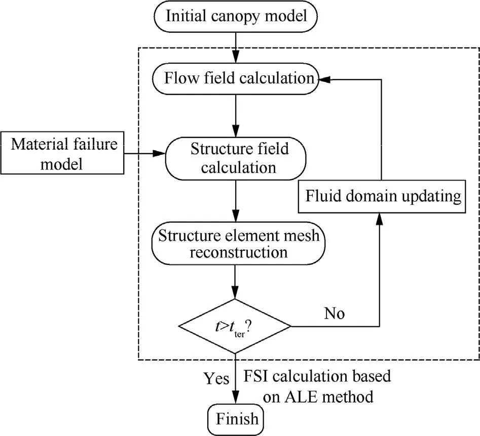
Fig.2 Coupling process with ALE method.
3.Numerical method
The Supersonic Ringsail (SSRS) parachute in Ref.38 is simulated with 20 panels and 24 gores.The main dimensions of SSRS parachute are shown in Fig.338and Table 1.As shown in Fig.4(a),the initial parachute structure is obtained by direct folding.The initial damage area in the experiment38is set as lower failure stress (80% of the original) to simulate the damage before inflation.As shown in Fig.4(b),its width and height of the fluid domain are 5D0and 7D0respectively, where D0is nominal diameter of parachute.The parameters of numerical method are shown in Table 2.The opening speed of the parachute system is 1.7Ma, 1.9Ma, 2.1Ma and 2.3Ma respectively to analyze the damage propagation mechanism of parachute at different opening speeds.

Fig.3 Geometry of ringsail parachute.38
4.Method validation
4.1.Parachute damage process
In order to verify the accuracy of the ALE method with material failure,the simulation results of ALE method both considering and ignoring material failure at 2.1Ma are compared with the flight test results.38Fig.5 compares the transient canopy shape between numerical simulation and flight test at different time in the inflation process.In this numerical work,damage first occurs as a small hole in the initial dangerous zone at 0.3 s and the damage propagates quickly to the adjacent rings (Fig.5(b1)).The damage edge in Fig.5(b3) is smoother than that in Fig.5(a3), because the canopy fabric is regarded as an ideal homogeneous thin shell in this study.After the damage occurs across the vent and further propagates (Fig.5(b3)), the canopy was completely torn in halves(Fig.5(b5)).The first appearance of the damage and the transient propagation process are consistent with the flight test(Figs.5(a1)-(a5)).However, in the traditional ALE method,the canopy maintains a stable hemispherical shape after full inflation without damage.Due to the absence of the material failure model, the propagation of tearing and cracks in the canopy fabric in inflation stage cannot be predicted by traditional structural methods.This also results in major difference in the flow and parachute performance.
Fig.6 compares the canopy projected area in inflation stage obtained from numerical simulation and flight test.In the ALE method without material failure, the canopy projected area increases first with the canopy inflation and then decreases to a steady value, because the canopy damage is not depicted.However, the canopy projected area in the ALE method with material failure shows deviation when the damage occurs.The projected area decreases persistently after the peak due to the increased damaged area in canopy(Fig.5).Comparison of the dynamic load in inflation process obtained by numerical simulation and flight test is shown in Fig.7.In the ALE method without material failure,the dynamic load shows similar trend with the projected area, while in the ALE method with material failure, the damage occurs before the maximum dynamic load is reached.And the dynamic load decreases with the damage propagation.In all, both the canopy projected area and dynamic load in the ALE method with material failure decrease finally and do not reach steady values,which are consistent with the test measurements.The first parachute dynamic peak is more obvious in our model compared with that in the flight test data at the initial canopy inflation stage,because the initial canopy apex in this study is folded relatively tighter than the test canopy.
Table 3 further compares the dynamic load of both simulation results and flight tests.The maximum dynamic load error of the ALE method without material failure and the ALE method with material failure are 29.1% and 6.7%, respectively.At 0.5 s, when the canopy was completely damaged(Fig.5(b5)), the dynamic load in ALE method with material failure drops to 105 kN and the flight test measures 112 kN;however, the dynamic load in the ALE method without material failure still maintains at a large value of 300 kN.This also indicates that the simulation of damage propagation is essential to accurately evaluate the aerodynamic performance of supersonic parachutes.

Table 1 Structure parameters of SRRS parachute.

Fig.4 Mesh model of supersonic parachute.
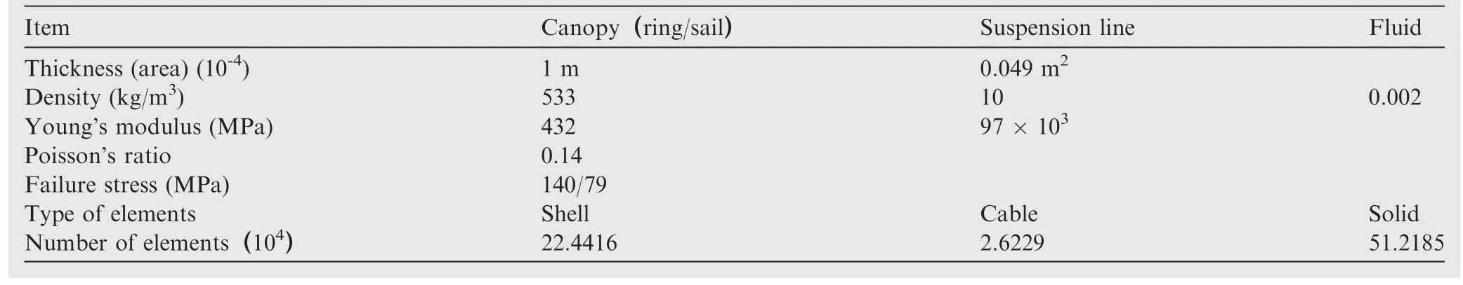
Table 2 Parameters of numerical methods.
4.2.Flow and structure field in inflation process
As shown in Fig.8(a),the compressible flow around the supersonic ringsail parachute can be divided into a number of canonical regions.The two turbulent wakes, T1and T2, form ahead of the capsule and the canopy,respectively.Two recompression shocks,S1and S2,are generated ahead of the capsule and the canopy, respectively (Fig.8(a1)).In the traditional ALE method, the flow field near the parachute maintains a stable symmetric structure in inflation process.However, in ALE method with material failure, remarkable changes of the flow field are observed near the parachute: the highspeed airflow flows into turbulent wake T2through the canopy initial damaged zone (Fig.8(b1)), and the airflow through the canopy damaged zone increases with the damage propagation(Fig.8(b2)).And the turbulent wake T1becomes wider due to the increased airflow through the canopy damaged zone.The canopy bow shock B2is disturbed by the unsteady wake(Fig.8(b4)).The airflow through the canopy damaged zone leads to the asymmetric change of turbulent wake T2and recompression shock S2(Fig.8(b5)).In turn, the fast flow increases the stress of the damaged canopy and promotes the damage propagation.As shown in Fig.8(c), in ALE method without material failure, canopy stress does not change significantly,while in ALE method with material failure,the canopy stress increases near the damaged area of canopy (Fig.8(d1))due to the interaction with the air flow.At 0.4 s,damage propagates to the vent and causes the stress concentration near the vent,and as a result,the damage propagates across the vent to another gore (Fig.8(d3)).This leads to the completely torn canopy at 0.5 s.
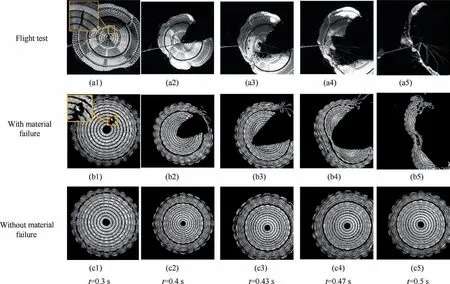
Fig.5 Canopy shape in inflation process.
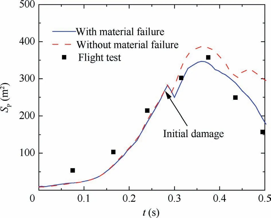
Fig.6 Projected area of canopy.
As shown in Fig.9, the stress at different locations on canopy,including the top ring(point L),the lowest ring(point M) and the lowest sail (point N), are analyzed.The maximum stress in ALE method without material failure is greater than that in ALE method with material failure, because damage increases the flow through the canopy and leads to the decrease of pressure inside the canopy.The maximum stress near the vent(point L)is greater than the maximum stress at the middle part of the canopy (point M), and the skirt (point N) is the smallest.This indicates that tearing damage is more likely to occur near the vent and this is consistent with the observation in supersonic parachute flight tests.13

Fig.7 Comparison of parachute dynamic load.
5.Effect of inflation speed on parachute damage
5.1.Flow field and canopy structure
Fig.10 shows the shape and stress distribution of the canopy in inflation process at different Mach numbers.At 1.7Ma,the parachute maintains its shape with spotted damaged area(Fig.10(a5)).Above 1.7Ma, the damage propagates and fur-ther tears the canopy because of the stronger interaction of the fast flow and the damaged canopy.At 1.9Ma, the damage propagates to the rings of the initial damaged gore, but the skirt is not completely damaged,and the canopy finally shrinks inward and collapses (Fig.10(b5)).At 2.1Ma, the damage propagates across the vent and the canopy is finally torn in halves (Fig.10(c5)).At 2.3Ma, the tearing directions show uncertainty and the shape of the damaged canopy is asymmetrical.This is because the initial damage occurs at multiple areas(Fig.10(d1)),so the tearing directions appear to be more random at high inflation speeds.

Table 3 Comparison of dynamic load between simulation and flight test.
Fig.8 Flow field and structure field near canopy in inflation process.

Fig.9 Stress variation at different positions of canopy.
Fig.11 shows the changes of canopy inflation time t1,initial damage time t2(the time when damage first occurs)and dimensionless damage time t0(t2/t1)with Mach number.The damage always occurs before the maximum dynamic load is reached.With the increase of Ma, the parachute encounters larger dynamic pressure, and this results in the smaller inflation time and faster increase of canopy projected area (Fig.12).The increased dynamic pressure also reduces the initial damage time and advances the damage propagation, because of the stronger interaction between the damaged canopy and the air flow.This explains that the canopy is not able to further inflate and the maximum projected area reduces at high Mach numbers.
Fig.13 shows the velocity contour of different Mach numbers at maximum dynamic load.At 1.7Ma, and the velocity field near canopy maintains a stable symmetrical structure because the parachute maintains its shape with minor damage.With the increase of Mach number, the canopy tearing speed increases, the airflow through the canopy damaged zone increases due to the increased canopy damaged area, and this leads to the wider turbulent wake T2at high Mach number.The asymmetry of the flow structure increases with Mach number.As a result, the parachute becomes more unstable and this also promotes the canopy damage.

Fig.14 Maximum stress at different positions of canopy.
5.2.Maximum stress and opening load
Fig.14 shows the maximum stress of different locations on canopy, and L, M and N denote the same locations in Fig.9.The maximum stress at different locations increases first and then decreases with increasing Mach number,and the time that the maximum stress is reached is earlier as the Mach number increases.The maximum stress is observed at 2.1 Ma.Below 2.1Ma, the air flow on the parachute increases with the increasing Mach number, and this increases stress.At 2.3Ma, the canopy damage propagates too fast (Fig.12) and the stagnation effect of the parachute on the airflow is weakened.This reduces the drag of the canopy and therefore the stress reduces compared with 2.1Ma.At all simulated opening speeds, the maximum stress is observed near vent, consistent with the observations in Section 4.2.The maximum stress at the vent is most affected by the flow velocity, and maximum stress at the bottom edge of the canopy is less affected by the flow velocity.This is mainly related to the angle of air flow interaction with the different areas on canopy.The velocity of the vent is perpendicular to the air flow direction, while the skirt is almost parallel to the air flow direction.
Fig.13 Velocity contour near canopy at different Mach numbers (t = t1).

Fig.15 Dynamic load in inflation process.
As shown in Fig.15, there are two dynamic load peaks in the opening stage at all simulated opening speeds.The first peak is caused by the oscillation of the skirt edge of the parachute in the early inflation stage.The second peak is the maximum dynamic load when the canopy fully inflates.The first peak occurs before the damage occurs, and therefore, the dynamic load is larger and occurs earlier when Ma increases.For the second peak which occurs when the damage already propagates, the trend is different.To further investigate the dynamic load change, the maximum dynamic load Fkmaxis shown in Fig.16.The maximum dynamic load value of the parachute increases with Mach number below 2.1Ma,the same with the first dynamic load peak,and then decreases at 2.3Ma.At 2.3Ma, the canopy is already torn into halves (Fig.10(d)),and the maximum dynamic load is greatly reduced.The failure dynamic load Fkf, which is the dynamic load of parachute when damage firstly occurs, increases monotonically with Mach number, because the dimensionless initial damage time increases as Mach number increases (Fig.11), which indicate that damage occurs at the time when canopy is closer to the full inflation state as Mach number increases.Notice what the maximum dynamic load is around twice higher than the failure dynamic load when Mach number is smaller than 2.1.This indicates that the parachute design based on the maximum dynamic load in the traditional research may underestimate hazards.
Fig.16 Maximum dynamic load and failure.load at different Mach numbers.
6.Conclusions
In this study, a new fluid–structure interaction method with a material failure model is proposed to simulate the damage of supersonic parachutes in the inflation process.The simulated canopy shape and the dynamic load are consistent with the flight test.The damage propagation mechanism of parachute at high flow speeds is investigated, and the effect of opening speed on the damage process is discussed.The main conclusions are drawn as follows:
(1) The damage tends to occur first at the initial weak position of canopy near the vent.During the opening stage,the spotted damage propagates along the parachute,propagates across the vent and tears the canopy into halves.Damage occurs before the maximum dynamic load is reached.
(2) The damaged area of canopy allows the high-speed air flowing through the canopy, which leads to the asymmetric change of the flow structure.In return, the fast flow increases the stress of the damaged canopy and promotes the damage propagation.
(3) The parachute maintains its shape with minor damage at 1.7Ma.Above 1.7Ma, the damage occurs earlier and spreads faster with the increase of Mach number.The canopy tears along the gore where damage first occurs below 2.3Ma.At 2.3Ma, the damage occurs at multiple areas and the tearing directions appear to be more random at high inflation speeds.
(4) The maximum dynamic load of the parachute occurs after the damage propagates.The maximum stress is observed near the vent.With the increase of Mach number,both the maximum dynamic load and the maximum stress increase first and then decrease.
(5) The dynamic load when damage occurs is proportional to the dynamic pressure.The parachute reliability evaluation based on maximum dynamic load in the traditional research can underestimate the hazards.
Declaration of Competing Interest
The authors declare that they have no known competing financial interests or personal relationships that could have appeared to influence the work reported in this paper.
Acknowledgement
This study was supported by the National Natural Science Foundation of China (No.11972192).
 CHINESE JOURNAL OF AERONAUTICS2023年10期
- CHINESE JOURNAL OF AERONAUTICS的其它文章
- Experimental investigation of typical surface treatment effect on velocity fluctuations in turbulent flow around an airfoil
- Oscillation quenching and physical explanation on freeplay-based aeroelastic airfoil in transonic viscous flow
- Difference analysis in terahertz wave propagation in thermochemical nonequilibrium plasma sheath under different hypersonic vehicle shapes
- Flight control of a flying wing aircraft based on circulation control using synthetic jet actuators
- A parametric design method of nanosatellite close-range formation for on-orbit target inspection
- Bandgap formation and low-frequency structural vibration suppression for stiffened plate-type metastructure with general boundary conditions