
Numerical simulation and experimental research on oscillation performance of disc-type jet oscillator
2023-11-10 02:18WutekuerNUERMAIMAITIXuewuLIUPengzeYANZongruiWANGDapenHU
CHINESE JOURNAL OF AERONAUTICS 2023年10期
Wutekuer NUERMAIMAITI, Xuewu LIU, Pengze YAN, Zongrui WANG,Dapen HU
School of Chemical Engineering, Dalian University of Technology, Dalian 116024, China
KEYWORDS
Abstract Based on active flow control technology, the two wall jets attached to a standard cylindrical surface due to the Coanda effect will output a detached jet when they collide.The direction of the output jets produced by this collision is very sensitive to small changes in the two wall jets.Therefore, a new type of curved-wall supersonic compressible disc-type jet oscillator is proposed by using the oscillating feedback jet as the source of wall separation.Through monitoring the internal flow field,the jet core’s pressure attenuation,the jet’s amplitude,and the wall pressure are analyzed.The results show that the disc-type jet oscillator model with a double-bend inlet has the best performance.After adding a multi-pipe outlet structure to the model, the oscillators with various disc diameters were simulated at different inlet pressures and air inlet frequencies to the wall-off control port.The oscillation performance of the disc jet oscillator is better when the diameter of the disc is 32 mm and 20 mm,and the included angle between the wall-off control port and the horizontal direction is 45°.Two kinds of oscillators of the same diameter as the model are experimentally studied, and the results prove the feasibility of the disc-type jet oscillator.
1.Introduction
Flow control refers to changing the state of motion by applying physical quantities, such as force, electromagnetism,momentum, and heat, to the moving fluid and then changing the shape of energy or movement of the object.It is usually divided into two categories: passive flow control and active flow control.1Much research has been done on passive flow control, and it has been widely used in airfoil and vortex generators.2,3Passive control mainly changes the flow state in the field by changing the devices or structures on the flow field.4However, the disadvantage of passive control is also pronounced.Once the deviation between the actual state of the flow field and the preset state is significant, the control effect will be challenging to achieve the preset requirement.The active flow control technology is to apply excitation or disturbance to the flow field.By coupling the flow of the original flow field and the applied excitation, the flow state and parameters of the actual flow field are changed to achieve the purpose of control.5Active flow control technology can overcome the defect that passive control cannot adapt to changes in the flow field and adjust control parameters.It can be seen that active flow control is up-and-coming research.Dynamic flow control mainly includes the following methods: blowing and sucking, synthetic jet, micro-jet, micro-blowing, plasma,Micro-Electro-Mechanical System (MEMS), magnetohydrodynamics, and adaptive structure of innovative materials.6
When the fluid is sprayed from a narrow space into a vast area outside, a jet will be formed.Under the diffusion action,the jet will exchange energy, momentum, and mass with the outside world.7,8Among them,the nozzle can convert pressure energy into kinetic energy through its structure,thereby spraying high-pressure fluids at high speed.Traditional jet oscillation uses the laminar flow characteristics of this single-nozzle jet9and the Coanda effect, relying on the internal structure of the jet oscillator to use the fluid as the power to induce the sector oscillation of the main jet.10–14Studies have shown that the oscillability of existing single-nozzle oscillators is limited by structure,easy to generate noise under high pressure,15and large loss of kinetic energy and pressure,resulting in most of the generated jet oscillators can only be used under lowpressure operating conditions, which also hinders the promotion and application of the oscillator itself.
According to the shape of the outlet part of the nozzle of the jet oscillator, it is divided into planar jets, circular jets and rectangular jets.16The proposed dual-nozzle jet generation method abandons the conventional single-nozzle mode of traditional jet oscillators.And dual-nozzles are widely used in supersonic fighter motion control,17and are also suitable for rocket propulsion systems.18,19Arrays and clusters of nozzles are now believed to increase efficiency and improve vehicle integrity and throttling capabilities significantly.In addition,array nozzles are also used in supersonic fuel injectors, soot blower devices,and thermal spray devices.20–23When multiple jets are close together, the flow field becomes quite complex.The interaction of the jet plume affects the mixing properties,lateral growth, and overall evolution of the jet flow field.24–26The two jet engines with smaller nozzle spacing have better sound insulation,which reduces howling.Because the jets from the closely spaced nozzles merge, the whistling is suppressed before the strong whistling of the higher modes develops.With more jets, the length of the supersonic core is longer.27The increase in core length is attributed to the interaction of multiple jets, resulting in a decrease in entrained fluid from the environment.Multiple jets prevent rapid fading of jet pressure.This just meets the need for flow pressure retention and noise suppression for jet oscillators.
Through the characteristics mentioned above of multiple nozzles,it is proposed that the jets are ejected from two nozzles to the curved wall,and the two jets collide and shoot out.This curved wall jet collision has a high sensitivity potential, especially when the surface has a cylindrical shape.28The two wall jets are ejected from the common air supply chamber through the same nozzles in parallel, bent to the cylindrical surface of the disc-shaped body by the Coanda effect,which leads to their head-on collision.The resulting synthetic jet is sensitive to small changes in the jet flow rate ratio, which is a profitable feature in pneumatic sensors.The connection of the two colliding curved wall jets with such a surface is excellent and is easily disturbed.29In this way, the direction of the jet can be changed.The structure of the disc jet oscillator is proposed by effective interference so that the fluid can produce periodic controllable oscillation.
This article discusses a new jet oscillator based on aerodynamic principles that have been studied so far (especially suitable for compressed gas operation).The jets ejected by the two nozzles are attached to the same cylindrical surface and collide at the ends and are ejected by the collision point as the jet direction.Among them, the most important is the discovery that destroys the symmetry of the two-sided fluid, which can make the jet directionality have a stable flow state.By adding the effective jet control point from this discovery, a disc jet oscillator can be designed,which is a periodic sector deflection of the jet.The jet oscillator can be miniaturized and can be integrated.Its structure is a simple,safe operation,not affected by radiation and electromagnetic waves, and has the advantages of corrosion resistance, earthquake resistance, and high and low-temperature resistance,and is suitable for application in various environments, such as aerospace, nuclear industry and other fields of certain control systems.
2.Description of oscillator model
2.1.Numerical simulation
The outlet structure of the previous jet oscillator nozzle is shown in Fig.1(a)as a straight nozzle model,and the disc nozzle model based on the multi-jet characteristics and curved wall jet collision characteristics is shown in Fig.1(b).Areas A and B are the jet oscillator high-pressure inlets and high-pressure outlets.Z is the straight nozzle width, Z = 5.0 mm; Z1and Z2are the nozzle widths on both sides of the disc nozzle,Z1= Z2= 2.5 mm; D is the diameter of the disc in the disc nozzle, D = 20, 24, 28, 32 mm.
The disc nozzle model is shown in Fig.1(b).The specific realization structure is to place a cylindrical structure at the center of the wider square jet nozzle.Half of the cylinder body forms a protruding semicircular structure outside the nozzle.The top and bottom are closed to form a symmetrical nozzle divided by a semicircle.When the fluid is introduced, the jet will emerge from the two split nozzles and adhere to the outer semicircle of the cylinder.They will collide and merge at the center below the cylinder into the oscillating cavity.
After preliminary simulation, the disk size and inlet structure of the better disc structure jet oscillator are determined.Add two off-wall control port nozzles to the disc.and the gas source of the wall-breaking control port comes from the outlet of the feedback jet to form a wall-off flow.The walloff flow enters one side of the circular curved wall so that the main jet of one side of the Coanda wall is separated from the wall in advance,and the stable Coanda state of the main jet of the wall is destroyed.The collision point of the main jet on both sides of the Coanda on the curved surface is shifted to one side.The jet continuously repeats the above process on both sides to generate periodic oscillations.
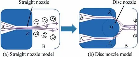
Fig.1 Nozzle model.
As shown in Fig.2, through the simulation, a pulsating jet function(UDF)is programmed to realize the regular air intake of the wall-off control port.The collision point of the main jet of Coanda is controlled by the periodic jets alternately ejected from the control ports on both sides to realize periodic deflection.At the same time,the pressure at the outlet,the jet pressure on the disc wall,and the velocity and pressure programs in the flow field were collected to analyze the periodicity, time uniformity, and oscillation stability of the internal process of the disc jet oscillator.The position of the nozzle and the jet frequency of the walloff control port on the disc were also changed to study the Coanda colliding jet’s control and oscillation effect.
This fluid flow structure can provide a new type of fluid oscillator with a simple design, which has the characteristics of a controllable period, high sensitivity, and slight jet energy loss.Because there are no moving parts and the maintenance cost is meager, it can be used for flow control in various hazardous locations,such as high-pressure natural gas transportation, nuclear energy, deep-sea exploration, and aerospace.Combined with the designed test setup and flow simulation,we can describe the oscillator’s internal flow path and oscillation characteristics.There are also two alternative types of breaking symmetry flow, where the direction of fluid flow is controllable.
2.2.Experimental design
In the experimental study, a disc structure jet oscillator is designed and manufactured, as shown in Fig.3.The inlet is connected to the air compressor, the pressure sensor is placed at the outlet,and the sensor’s measurement technology used is the transient pressure measurement technology.The pressure sensor provides inlet pressure ranging from 0.1 MPa to 1.0 MPa.The sampling frequency was 500 kHz, and the recording time was 3 s.
On the disc structure,the alternate air intake of the wall-off control port can be realized by connecting a small oscillator,as shown in Fig.2.The two outlets of the small feedback oscillator are respectively connected with the two wall-off control ports of the disc structure jet oscillator.Different air outlet frequencies can be obtained by changing the feedback hose length to realize alternate air intake at a particular frequency at the control port on the disc structure.Assemble the small oscillator and the disc structure jet oscillator as shown in Fig.3,connect the inlet to the air compressor, and change the inlet pressure (0.2, 0.3, 0.4, 0.5, 0.6 MPa).Furthermore, change the tube length (300, 600, 1100 mm) of the feedback tube of the small oscillator, connect the pressure sensor to the outlet,and measure the outlet pressure of Outlet 1,Outlet 2,and Outlet 3, respectively.
The compressed air supply system and measurement system of the jet oscillator are shown in Fig.3,and the compressed air supply system is mainly composed of an air compressor, pressure control valve and bypass valve,connecting pipe,and precision pressure gauge.The compressor is manufactured by Ruitai Machinery Co., Ltd., with a rated working pressure of 1.25 MPa, a nominal volumetric flow rate of 1.05 m3/min,and a model number of W-1.05/12.5.The measurement system consists of a high-frequency dynamic pressure sensor, a positive and negative integrated power supply,an A/D conversion board, a data acquisition board, and a computer.The fourchannel high-speed data acquisition board model is PCI8757,each channel has a sampling frequency of 800 kHz,and is produced by Beijing Altai Technology Development Co., Ltd.High-frequency dynamic pressure sensor is produced by Kunshan Shuangqiao Sensor Measurement and Control Technology Co., Ltd., with an acquisition frequency of 200 kHz, an accuracy of 0.5% full scale, a range of 0–1 MPa, and a model of GYC1401F.

Fig.2 Schematic diagram of oscillator principle.

Fig.3 Experimental process and physical map.
3.Numerical analyses
3.1.Nozzle structure
3.1.1.Effects of different nozzles structures on jet core
The research first considers the nozzle structure,and it is found that different designs significantly influence the jet end loss.Suppose the number of jets increases and the entrainment of the jets decreases,the diffusion rate will decrease.In that case,the jet will decay slowly, and the core length will increase accordingly, effectively reducing the jet loss.Therefore, we tried to change the traditional nozzle structure.According to the characteristics of a double jet combined with one jet on a curved wall, a disc nozzle is proposed.It carried out preliminary simulation verification under the condition that the jet fluid (such as high-pressure air) is a compressible supersonic fluid.Fig.4 shows the attenuation curves of the jet core of the two injection methods (straight nozzle and disc nozzle),where Sections a–d are the pressure sections at different distances from the nozzle.
From the comparison between Figs.4(a) and (b), it can be seen intuitively that the core pressure of the double-inlet disc structure at the monitoring surface of x = 85 mm is 0.19 MPa, which is significantly higher than the core pressure of the standard nozzle of 0.15 MPa.It can be seen that the core decay rate of the new disc structure is slower,and the pressure retention performance is better than that of standard nozzles.
3.1.2.Effects of different nozzle structures on jet amplitude
When the jet enters the low-pressure fluid domain, it will entrain the surrounding static fluid into the jet, causing the two to mix and move forward.This entrainment and mixing effect can cause the jet flow to be unstable and deflected to the left or right.By monitoring the jet pressure at the flow field section at a vertical distance of x = 50 mm from the nozzle,the difference between the top left and right deflection positions at the jet core (the highest pressure point) is obtained.This difference is the jet amplitude.We can use this amplitude as one of the evaluation indicators to evaluate the advantages and disadvantages of the jet flow control performance of the disc structure jet oscillator.
Fig.5 is a comparison chart of the amplitudes at the horizontal distance x = 50 mm from the nozzle for nozzles with different diameter disc structures and ordinary straight nozzle structures under the condition that the pressure ratio is 3.The red line is the jet amplitude of the straight nozzle structure,which is about 16 mm, and the black line is the jet amplitude of the double-inlet disc nozzle.It can be seen from Fig.5 that the outgoing jet amplitude of the disc structure is smaller than that of the standard straight-type nozzle.It can be seen that the disc structure nozzle can realize jet control more easily.
3.1.3.Influence of diameter of disc on wall-off position
A semicircular monitoring surface was set up in the jet core area 1.25 mm away from the edge of the disc,and the monitoring range θ was from–90°to 90°.The significance of establishing this monitoring surface is to intuitively see the wall attachment of the jet on the disc surface after the jet exits the nozzle, the starting position of the wall separation, and the collision position of the two jets, which is convenient for analyzing the behavior of the jet on the wall.

Fig.4 Attenuation curves of jet cores for two injection methods (straight nozzles, disc nozzles).

Fig.5 Comparison of simulated jet amplitudes with disk diameter.
Fig.6 shows the two jets that start attaching to the disc wall from the 90°and–90°positions.At this time,the wall and inlet pressure are roughly equal,which is about 0.3 MPa.When the diameter of the disc is 32 mm, the jet wall pressure begins to decrease suddenly at the position of θ = 15°, indicating that the jet starts to break away from the wall.It can be seen for the same reason that when the diameter of the disc is 28 mm,the jet will break off at the position of θ=21°.When the disc diameter is 24 mm, the jet will leave the wall at θ = 25°.It can be seen that the smaller the diameter of the disc,the more forward the position where the jet starts to come off the wall after it attaches to the wall.
3.1.4.Influence of disc position on jet direction
Two curved wall jets collide at the center of the disc and output a combined jet.This collision point is extremely sensitive to the magnitude of the jet flow on both sides.Therefore, by changing the size of the nozzles on both sides,the collision point can be changed, so that the direction of the jet is changed.When the disc moves to one side, the nozzle size changes twice.The disk movement distance and jet deflection angle are shown in Fig.7.The ratio of the flow of the jets on both sides determines this slope, which affects the direction of the jet.Since this disc structure is essentially just a special-shaped airflow cavity, the direction of the jet can be precisely controlled by this feature.

Fig.6 Monitoring diagram of disc surface pressure.

Fig.7 Schematic diagram of disc jet gas deviation.
Based on the boundary layer characteristics of the curved wall jet, and the wall of the jet can change the collision point of the two jets,which directly leads to the change of the direction of the jet.According to this feature,we designed a control method for changing the direction of the jet, that is, forcibly changing the wall breaking point of the jet so that it changes to change the direction of the jet.The specific structure is shown in Fig.1, and a detailed study has been conducted.
3.2.Structural analysis of disk-type oscillator’s wall-off control port
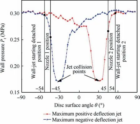
Fig.8 Jet wall pressure at position of maximum deflection of jet.
Based on the previous double-inlet disc structure(32 mm),the outlet of the original model was changed to a six-outlet design.Moreover,two wall-off control ports are added to the disc for controlling jet deflection.The two wall-off control ports realize periodic jetting through UDF files, and the alternate jetting frequency of the wall-off control ports is 100 Hz.Referring to the method of setting the monitoring surface to monitor the wall pressure of the jet when the jet is deflected to the upper and lower maximum positions, the simulation results are shown in Fig.8, where the solid black line in the y-axis direction marks the angle corresponding to the nozzle angle of the wall-off control port of 45° and the position where the jet starts to break away from the wall.The blackdisk-type indicates the part of the collision point where the two jets meet.The two jets start to attach to the disc wall from 90° and–90° positions, and the jet currently is not affected by the wall-off control nozzle, so the wall pressure monitored at this position is basically the same as the inlet pressure, both about 0.3 MPa.The position where the wall pressure suddenly drops is the position jet starts to peel off after being subjected to the wall removal control port.Fig.8 shows a specific positional deviation between the nozzle of the wall removal control port and the starting point of the wall removal.Furthermore, the Coanda jet starts to come off the wall before the place where the jet from the nozzle of the wall-off control port is ejected,and the jet collision point is after the wall-off position.
Considering that the position of the nozzle of the wall-off control port on the disc may have a particular influence on the oscillation of the jet oscillator and the breakaway effect,it is thought that the position of the wall-off control port can be changed for simulation.Changed the wall-off control ports where the center of the disc is 45° from horizontal to 30° and 60° positions.The inlet pressure, the initial pressure of the field’s flow field,and the inlet pressure set by the nozzle of the wall-off control port are consistent with the previous simulation parameter setting method, as shown in Fig.9.
The position of the jet wall-off is near the nozzle of the wall-off control port, and it can be seen from Fig.10(a) that when the nozzle of the wall-off control port is at an angle of α=30°with the horizontal direction.It is difficult for the jets formed by the two jets that collide from the wall to reach the oscillating bottom tube,resulting in a small amplitude of oscillation that can be controlled and a poor oscillating effect.From Fig.10(c), when the nozzle of the wall-off control port is at an angle of α = 60° with the horizontal direction, the jet attached to the wall starts to be ejected from the lower inlet.It then only attaches to the wall for a short distance on the disc before being excited off the wall.The jets injected from the upper inlet are equivalent to free wall separation without being affected by the wall-off control port.In this case, the separation points of the two jets injected from the two inlets are too far apart.As a result, the two jets detached from the wall will collide and merge after they flow for a longer distance in the flow field.In this case, the jets will be turbulent after they join,which will affect the total pressure retention rate of the jet oscillation to a certain extent.Through the comparison and analysis of cloud images,the nozzle position of the three kinds of wall-off control ports has a better effect of α = 45°.
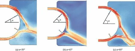
Fig.9 Schematic diagram of nozzle positions of different wall-off control ports.

Fig.10 Velocity program of entire flow field when nozzle positions of wall-off control port are α = 30° and α = 60°.
By monitoring the wall pressure on a disc with two wall-off control nozzle positions, the wall-off and wall-attached states of the resulting wall jet when the jet is deflected to the maximum position is analyzed.In Fig.11, the solid black line in the y-axis direction is used to mark the angle corresponding to the position of the nozzle of the wall-off control port and the place where the jet begins to break away from the wall.When the nozzle of the wall-off control port is at an angle of α = –60° with the horizontal direction, the jet will start to wall-off near the tip of α = –65°.When the nozzle of the wall-off control port is at an angle of α = –30° with the horizontal direction, the jet will be separated from the wall near the tip of α=–36°.There is a 5°–6°deviation between the nozzle position of the wall-off control port and the place where the jet starts to peel off, and the part where the jet begins to peel off is always before the nozzle position of the wall-off control port.

Fig.11 Pressure map of disc wall at maximum deflection of jet when nozzle is at different positions on disc.
3.3.Periodic oscillation performance of disk oscillator
3.3.1.Time uniformity of jet oscillation
Time uniformity is also one of the indicators to evaluate the performance of the oscillator, that is, whether the time distribution of the oscillating jet emitted by the six-outlet tubes A,B, C, D, E, and F in one cycle is relatively uniform.To determine this index,use the simulated oscillation results of the disc jet oscillator with different disc diameters of 20,24,28,32 mm.Then take the wave width corresponding to each outlet tube in the three cycles after the oscillation is stable, and bring the average value of the time obtained by the wave width corresponding to the abscissa.In this way, the duration of the jet ejected from each oscillating tube can be accurately obtained in one cycle.A percentage stacking graph of the time the jet is removed from the six-outlet tubes in one process is shown in Fig.12.From Fig.12, the proportion of the time when the jet is ejected from each oscillating tube in one cycle can be obtained so that the advantages and disadvantages of the time uniformity of the oscillator can be compared.

Fig.12 Proportion of jetting time in each outlet tube of different oscillators.
The top yellow background column data is the jet time proportion of each oscillator tube of the standard feedback oscillator.It can be seen from Fig.12 that the jet time of the two tubes, A and F, accounts for the most.It is much larger than the jet time of the two middle oscillator tubes,C and D.That is to say, the jet of the ordinary feedback oscillator is mainly emitted from the oscillating tubes on both sides in one cycle,and the time that the jet is ejected from the middle oscillating tubes is minimal.The jet time ratio of the disc jet oscillator is marked with a blue background,although the jet time ratio of the A and F tubes is still the largest.However,the time proportion of the jets emitted by the four tubes B,C,D,and E in one cycle is significantly higher than that of the conventional feedback jet oscillator.It can be seen that the disc structure has a significant optimization effect on the time-uniform performance of the fluidic oscillator.It can also be seen that the disc jet oscillator has a more significant advantage in controlling the high-speed switching of the jet in different pipelines.There are several disc jet oscillators with varying disc diameters in Fig.12.From the perspective of time uniformity,the time uniformity performance of the oscillator is better when the disc diameter is 32 mm.
3.3.2.Jet pressure retention rate
The ratio of the outlet pressure to the inlet pressure is called the total pressure retention rate, and the total pressure retention rate is one of the leading indicators to evaluate the performance of the jet oscillator.The higher the total pressure retention rate, the smaller the pressure loss of the fluidic oscillator and the better the version of the fluidic oscillator.The inlet pressure is from 0.2 MPa to 0.6 MPa,and the outlet pressure is 0.1 MPa.Take the average outlet pressure value of three cycles after the oscillator oscillates stably and calculate the total pressure retention rate-pressure ratio line chart,as shown in Fig.13.As the pressure ratio increases, the total pressure retention rate will gradually decrease.When the pressure ratio exceeds 6, the total pressure retention rate can be maintained above 50%.According to the analysis of Fig.13, the total pressure retention rate of the jet oscillators with a disc diameter of 20 mm and 32 mm is relatively high, and the changing trend of the tactual pressure retention rate is pretty good with the increase of the pressure ratio.
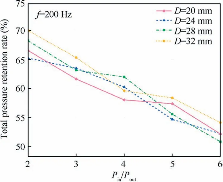
Fig.13 Total pressure retention for different diameters.

Fig.14 Total pressure retention at different frequencies.
We considered that the frequency f of alternating air intake at the control port on the disc might have a particular impact on the total pressure retention rate of the disc jet oscillator.As shown in Fig.14,it can be seen that the total pressure retention rate decreases with the spray rate of the nozzle wall removal control port for the disc jet oscillators with two different diameters.As the control port jet switching frequency increases,the total pressure retention rate gradually decreases, from 75% to 55%.When the inlet frequency of the wall-off control nozzle is 50 Hz, the oscillator performs the best in the performance of the total pressure retention rate.For the comparison of the two diameters of oscillators, the total pressure retention rate of the oscillator with a disc diameter of 32 mm is about 5%higher than that of the oscillator with a disc diameter of 20 mm at various wall-off control port frequencies.
4.Experimental results and analysis
CFD numerical simulation was used to study the characteristics of disc jet oscillators with different diameters, especially the total pressure retention rate compared with multi-outlet fan swing jet oscillators, indicating its significant advantages.Based on the numerical calculation results, this section selects the experimental model for optimizing the structure size processing and conducts experimental research on the disk jet oscillator.The experimental setup is shown in Fig.3.
Using the experimental model of a disc jet oscillator with different disc diameters and other sizes of the same size,adjust the nozzle inlet pressure Pin= 0.3 MPa, the outlet is atmospheric pressure.The simulated outlet pressure and experimental outlet pressure over time t are shown in Fig.15.The pressure waveforms of Outlet 1 of the D = 20 mm and D = 32 mm disc jet oscillators are shown in Figs.15(a) and(b), respectively.
It can be seen from Fig.15 that the trend of the experimental waveform of the disk oscillator is consistent with the simulation.The pressure values obtained by the experimental measurement curves of both disc jet oscillators were lower than in the simulation.D=20 mm disc jet oscillators were reduced to a greater extent, by 17.5%.The D = 32 mm disc jet oscillator has a relatively small degree of reduction, 8.3% lower than the numerical analog value.It shows that for the disk jet oscillator, the CFD numerical calculation result is high(which may be caused by the two-dimensional simplification of the disk structure), and it also shows that the sensitivity of D = 20 mm disk oscillator performance degradation is greater than the deviation of the optimized geometric parameters.Under the condition that the experimental measurement values of the two sizes of disc jet oscillators are reduced compared with the numerical simulation values, the energy efficiency characteristics and jet oscillation performance of the D = 32 mm disc jet oscillator are better than those of the D = 20 mm disc jet oscillator.In particular, it can be seen from the slope,peak and clutter number of the waveform that the oscillation performance of the jet oscillator with D = 32 mm is relatively stable, and the proportion of jet switching period is short,and the outlet pressure retention rate remains high.
As shown in Fig.16, it can be observed that both disc size jet oscillators produce stable periodic jet oscillations, and the jet uniformity of Outlets 1, 2 and 3 reaches 17.0%, 16.8%and 16.3%, which verifies the jet uniformity characteristics in numerical simulation.It can also be observed that the pressure waveform of the symmetrical outlet will have a slight deviation, and the analysis of the reason can be seen that this is an error caused by the accuracy of machining.
The outlet of the disc jet oscillator is designed as a symmetrical 6 outlet structure,and the outermost side is named Outlet 1, Outlet 2, and Outlet 3 in turn, because it is a symmetrical structure, only one side is named.In the experiment, the pressure waveform at the inlet and outlet of the jet oscillator were measured simultaneously with a high-frequency dynamic pressure sensor.First of all, we aim the high-frequency pressure sensor at the six outlets of the jet oscillator and collect its dynamic pressure at a distance of about 5 mm from the outlet,too close will cause pressure concentration inside the oscillator,destroying the stable oscillation of the jet.In addition,the voltage(time average)output by the pressure sensor at the branch outlet and the main jet inlet is converted into the absolute voltage ratio,which is defined as the experimentally obtained total pressure retention rate K.K is a measure of energy loss of the experimental oscillator.
For a determined Pin/Pout,it can be observed that for small feedback fluidic oscillators,the period increases monotonically with the length of the feedback loop.According to the experimental data analysis, when the small oscillator’s feedback tube diameters are 300,600,1000 mm,the oscillation frequencies are 500, 300, 125 Hz, respectively, that is, the intake frequency of the control port.The total pressure retention rate was calculated using the outlet pressure measured in the experiment, as shown in Fig.17.
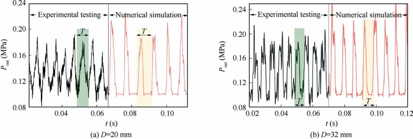
Fig.15 Comparison of experimental and numerical simulated pressure waveforms at Outlet 1.

Fig.16 Measures outlet pressure waveforms of two oscillators.
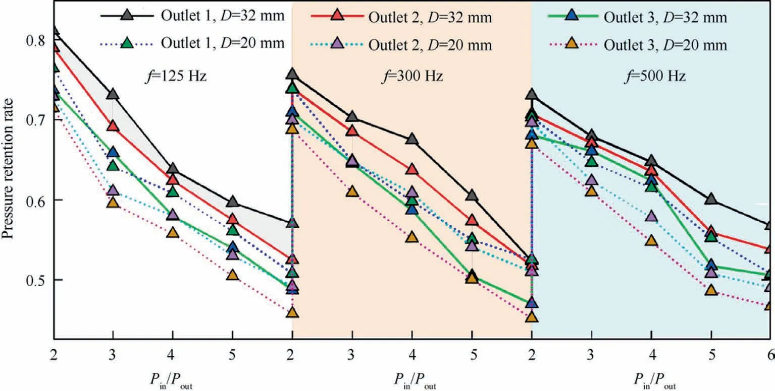
Fig.17 Pressure retention rate of each outlet pipe under different pressure ratios and disc diameters.
The pressure retention rate with a disc diameter of 32 mm is always better than that of an oscillator with a disc diameter of 20 mm.It can be seen that the disc diameter of 32 mm is a better oscillator structure,which is consistent with the simulation results.It can be seen from the analysis of Fig.17 that as the oscillation frequency increases,the total pressure retention rate of the outlet tube will gradually decrease, and the total pressure retention rate is better under the condition of a highpressure ratio, which is consistent with the simulation results.However,the pressure retention rate obtained from the experiment is lower than the simulation result.The preliminary analysis is the influence of the experimental air tightness, gas friction, and measurement error.Comparing the pressure retention rates of the three outlet pipes with the same pressure ratio and oscillation frequency,the oscillation of Outlet 1 is the best,Outlet 2 is the second,and Outlet 3 is the worst.The pressure retention rate of a jet oscillator with a disc size of 32 mm is consistently better than that of an oscillator with a disc size of 20 mm, which also confirms our analysis in numerical simulations.
5.Conclusions
(1) The dual-inlet disc nozzle structure and the conventional straight nozzle structure are simulated and compared.The simulation pressure analysis, core pressure attenuation,jet amplitude analysis,and wall pressure analysis of each monitoring surface in the flow field of different structures are obtained from the simulation.It is found that the disc nozzle has the advantages of a higher pressure retention rate,slower core decay,smaller jet amplitude, and strong directional controllability.
(2) After adding the wall-off control port and outlet tube structure to the disk nozzle model, the model was simulated under different disk diameters, inlet pressure, and inlet frequency of the control port.Performance parameters such as outlet pressure waveforms, wall pressure,jet time uniformity, and total pressure retention were analyzed.It is concluded that the disc diameter of the disc jet oscillator is 20 mm and 32 mm, and the oscillation performance is better when the angle between the nozzle and the horizontal direction of the wall-off control port on the disc is 45°.
(3) For experiments, two kinds of disc-type jet oscillators with 20 mm and 32 mm disc diameters were made.The experimental results show that the total pressure retention rate will decrease with the increased oscillation frequency and pressure ratio.The total pressure retention rate of the oscillator with a disc diameter of 32 mm is better than that of 20 mm.
Declaration of Competing Interest
The authors declare that they have no known competing financial interests or personal relationships that could have appeared to influence the work reported in this paper.
Acknowledgements
This study was co-supported by the National Key Research and Development Program of China (No.2018YFA0704601)and the National Natural Science Foundation of China (No.21776029).
 CHINESE JOURNAL OF AERONAUTICS2023年10期
- CHINESE JOURNAL OF AERONAUTICS的其它文章
- Experimental investigation of typical surface treatment effect on velocity fluctuations in turbulent flow around an airfoil
- Oscillation quenching and physical explanation on freeplay-based aeroelastic airfoil in transonic viscous flow
- Difference analysis in terahertz wave propagation in thermochemical nonequilibrium plasma sheath under different hypersonic vehicle shapes
- Flight control of a flying wing aircraft based on circulation control using synthetic jet actuators
- A parametric design method of nanosatellite close-range formation for on-orbit target inspection
- Bandgap formation and low-frequency structural vibration suppression for stiffened plate-type metastructure with general boundary conditions