
A novel method to eliminate the bending-induced collapse of hexagonal honeycomb
2023-11-10 02:16YujunLIZhiyongZHAOChungLIUQiLIULishuiSUNJunbioWANG
CHINESE JOURNAL OF AERONAUTICS 2023年10期
Yujun LI, Zhiyong ZHAO, Chung LIU, Qi LIU, Lishui SUN,Junbio WANG
a School of Mechanical Engineering, Northwestern Polytechnical University, Xi’an 710072, China
b AVIC Xi’an Aircraft Industry Group Company Ltd., Xi’an 710089, China
KEYWORDS
Abstract A novel grooving method for eliminating the bending-induced collapse of hexagonal honeycombs has been proposed, which lies in determining the appropriate grooving parameters,including the grooving spacing, angle, and depth.To this end, a framework built upon the experiment-based, machine learning approach for grooving parameters prediction was presented.The continuously grooved honeycomb bending experiments with various radii, honeycomb types,and thicknesses were carried out,and then the deformation level of honeycombs at different grooving spacing was quantitatively evaluated.A criterion for determining the grooving spacing was proposed by setting an appropriate tolerance for the out-of-plane compression strength.It was found that as the curvature increases,the grooving spacing increases due to the deformation level of honeycombs being more severe at a smaller bending radius.Besides,the grooving spacing drops as the honeycomb thickness increases,and the cell size has a positive effect on the grooving spacing,while the relative density has a negative effect on the grooving spacing.Furthermore, the data-driven Gaussian Process (GP) was trained from the collected data to predict the grooving spacing efficiently.The grooving angle and depth were calculated using the geometrical relationship of honeycombs before and after bending.Finally, the grooving parameters design and verification of a honeycomb sandwich fairing part were conducted based on the proposed grooving method.
1.Introduction
Inspired by nature, Nomex honeycomb composite structures have many excellent properties, such as lightweight,high stiffness, high modulus, and good thermal insulation.They are widely used in various fields, especially in aerospace, marine,automotive, and civil engineering, as excellent heat loadbearing, insulation and impact-resistant structures.1–5Traditionally, honeycomb sandwich structures are fabricated in a two-step process in which the prepreg face sheets are cured and then bonded to the honeycomb core with adhesives.
High-quality and efficient fabrication of Nomex honeycomb sandwich structures is still challenging due to the intrinsic properties of Nomex honeycombs, such as thin cell walls,discontinuous cell structure (hexagonal), and soft and brittle properties of the cell walls.Extensive work has been carried out to reduce or eliminate manufacturing defects that may affect the mechanical properties of the sandwich structure and to improve the manufacturing quality of Nomex honeycomb structures.6–12Anders et al.6,7used an in situ visualization method to directly observe the skin/core bond line under realistic autoclave conditions.Initially, the in situ cocure fixture with temperature and pressure sensors was designed to shed light on physical phenomena that are not observable in a traditional manufacturing setting.6Then, they proposed an in situ diagnostic method to address the challenge that scientific understanding of the complex and interacting phenomena that cause defects remains incomplete.Finally,an effective method by in-bag pressurization was proposed to avoid bond-line defects, which can avoid much of the trial-and-error effort typically associated with in-process defect detection.7In addition, Kermani et al.8–10demonstrated the physics of the co-cure process and bond-line formation of the adhesive joint and reduced or eliminated defects such as porosity and poorly formed fillets of the bond-line by optimizing the process parameters.They revealed that an adhesive with perforations to bond the honeycombs and face sheets would reduce the bond-line porosity compared to a nonperforated adhesive.9Three parameters, including the initial radius of voids, the initial porosity of the bond-line, and the interplay between the stability map and the process cycle,play an important role in the prediction of the final porosity within the bond-line.10
However,the above studies are all restricted to the analysis of flat honeycombs.In most of aerospace applications,honeycomb sandwich structures usually have a curved shape to provide a smooth aerodynamic configuration, such as wing fairings,wing flaps,spoilers,wing leading edges,engine cowls,and radomes.4,5,13–16The manufacturing process of these highperformance structures consists of bending the honeycombs and bonding the face sheets using a co-curing or co-bonding process.17,18More specially, the forming of polymer matrixbased honeycombs is conducted at elevated temperatures by using the visco-plastic properties of the matrix material.Subsequently,the deformed honeycomb is bonded to the face sheets using a co-curing or co-bonding process.18During the bending process,the Poisson effect of the hexagonal honeycombs leads to significant anticlastic (saddle-shaped) curvature when subjected to out-of-plane bending loads.19Node bond failures,local buckling, and collapse of honeycomb cell walls can be caused by the separation of adjacent honeycomb cores and the squeeze between honeycomb cores due to bendinginduced in-plane deformations of core cells during the formation of complex curvature structures,18,20–23which pose limitations on the forming of these structures.In our previous study,the obtained results have shown a correlation between processinduced imperfections and bending curvature and a much smaller deformation level of honeycomb at a larger bending radius.23These geometrical imperfections have a significant effect on the mechanical properties of the honeycombs, especially for bending radius.24As the bending curvature increased from 0 mm-1to 0.01 mm-1, the out-of-plane compressive initial peak stress of the honeycomb decreased by 16.20%.It is true that there are honeycombs with a different cross-section(e.g., Hexcel flex-core, square core) that can be bent while maintaining the integrity of the cells.25However, the hexagonal honeycomb generally has better crushing performance and is more commonly used than the square and flex-core cell configurations.26,27Pehlivan and Baykasog˘lu26experimentally investigated the effect of cell configurations on the crushing responses of Carbon Fiber Reinforced Plastic (CFRP) honeycombs.The results show that the compressive strength of the hexagonal specimens was better than that of the square and circular specimens.Wang et al.27compared the out-of-plane impact behavior of six types of honeycombs with reentrant,triangular, hexagonal, square, and two circular cells using numerical simulations.The hexagonal honeycomb performed better than the reentrant, triangular, and square honeycombs but worse than two circular honeycombs.
There is a critical and continuing need for improved manufacturing quality and efficiency in the fabrication of curved hexagonal honeycomb structures, which today are still often based on trial-and-error approaches.This fact is due to the lack of a standardized method for manufacturing curved honeycomb structures.Therefore,it is necessary to develop a comprehensive framework for the bending forming of curved hexagonal honeycomb structures.The current work extends our previous work on the formability of hexagonal honeycombs23and the performance analysis of honeycombs after bending.24It intends to explore a novel hexagonal honeycomb grooving method for eliminating or reducing bending-induced honeycomb collapse.The essence of the method is releasing the local stress by removing redundant material.The key is determining the appropriate groove parameters (mainly the grooving spacing, angle, and depth).This paper is organized as follows.Section 2 presents the geometry and material of the Nomex honeycomb specimens, as well as the mechanism and framework of the honeycomb grooving method.Section 3 describes the continuous grooved honeycomb bending and out-of-plane compression tests for collecting grooving spacing data and a data-driven grooving spacing prediction method using the Gaussian Process (GP).In Section 4, a criterion for determining grooving spacing, angle, and depth is proposed.In Section 5, an example for predicting and verifying the groove parameters of a cladding part is described.
2.Materials and grooving method
2.1.Honeycomb geometry and materials
The schematic representation of the Nomex honeycomb investigated in this work and the common notation used to describe the geometric parameters of a honeycomb cell are illustrated in Fig.1.The three principal directions of the honeycomb are referred to as Thickness Direction (TD), Transverse Direction(WD),and Ribbon Direction(LD).The honeycomb cell size is c, the wall length is le, the wall thickness is t, and the angle between the inclined cell wall and the horizontal is θ.The honeycombs are made from phenolic resin-impregnated aramid paper through an expansion process.The cell walls of the Nomex honeycombs are a three-layer structure,i.e.,an aramid paper layer is bonded by two phenolic resin layers on each surface of the aramid paper layer.Three types of honeycombs with different relative density, ρ*, and cell size, c, are considered in this study, and the above geometrical parameters of these honeycombs are listed in Table 1.

Fig.1 Scheme of honeycomb specimen and honeycomb cell’s geometry configuration.
2.2.Honeycomb grooving method
Due to the honeycomb cells’ resistance to buckling deformation during bending,a local stress concentration occurs,which leads to the local collapse of the honeycomb cell walls, as shown in Fig.2.23A grooving method is proposed in this study to release the local stress and further eliminate or reduce the collapse of the honeycombs.The schematic diagram of the honeycomb grooving method is shown in Fig.3.The groove is V-shaped and defined by the parameters including grooving spacing, l, angle, α, and depth, H.The V-shaped groove is formed by ultrasonic vibration-assisted cutting to avoid defects such as tears and burrs.28–30The applicability and the determination of suitable grooving parameters for the honeycomb grooving method are critical and will be discussed in the following sections.In addition,since the bending capacity of honeycombs along WD is better than in other directions, the bending of honeycombs along WD is adopted in this study.
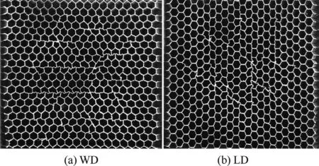
Fig.2 Nomex honeycomb bending along: (a) WD and (b)LD.23.
The operation procedure for determining the groove parameters (mainly grooving spacing) is illustrated in Fig.4,mainly containing three steps.First, bending tests were performed with different types and thicknesses of continuously grooved honeycomb cores in various semicircular molds, as shown in Fig.4(a).The configuration of deformed honeycomb cells’ top surface was derived with different grooving spacings and transformed into an in-plane digital image for deformation analysis.Then, the honeycomb’s deformation level was assessed quantitatively, and the relationship between the honeycomb’s deformation and the compressive strength was established,as shown in Fig.4(b).By specifying a suitable tolerance for the out-of-plane compression,the deformation range of the honeycomb can be determined.It can further obtain theappropriate grooving spacing for different honeycomb types and thicknesses at different bending radii.Finally, a Gaussian Process(GP)based data-driven model is synthesized to efficiently predict the grooving spacing, as shown in Fig.4(c).

Table 1 Geometry of honeycombs.

Fig.4 Operation procedure to determine the grooving spacing.
3.Experiments and parameters prediction method
3.1.Bending experiments
To assess the deformation of the honeycomb after bending, a series of continuously grooved bending tests were performed on three types of honeycombs in various semicircular molds with radii ranging from 50 mm to 350 mm.The test specimens were cut from three large sheets of 10 mm,20 mm,and 25 mm thickness.All test specimens have a uniform width of 150 mm.The experiments were carried out on an ETM104C testing machine at a constant speed of 2 mm/min with at least three repetitions to eliminate random measurement errors.The experimental setup and the continuously grooved honeycomb specimens are shown in Fig.5(a) and (b).Each specimen contains seven different grooving spacing and the same angle and depth, as shown in Fig.5(c).The dimensions of part continuously grooved NRH-2.7–48 honeycomb specimens are listed in Table 2.
The bending tests on the continuously grooved honeycomb specimens are presented as follows.First, the specimen is placed in the center of the bottom mold.Then,the upper mold is loaded until the lower surface of the honeycomb is completely in contact with the bottom mold.Finally,the specimen and the mold are glued together firmly, as shown in Fig.5(d).After bending, the top surface configuration of the deformed honeycomb cells was extracted and then converted into an in-plane digital image for deformation analysis, as shown in Fig.5(e).To quantitatively assess the honeycomb’s deformation level effectively,the Harris detector algorithm was applied to identify the vertices of each cell wall.31,32After determining the coordinates of all vertices, the honeycomb cells are reconstructed by connecting these vertices with straight lines, as shown in Fig.5(f).
Using the method proposed in Ref.23to evaluate the deformation of honeycombs, the deformation of honeycombs with different grooving spacing was calculated,which was then used to determine the appropriate grooving spacing.
3.2.Out-of-plane compression experiments
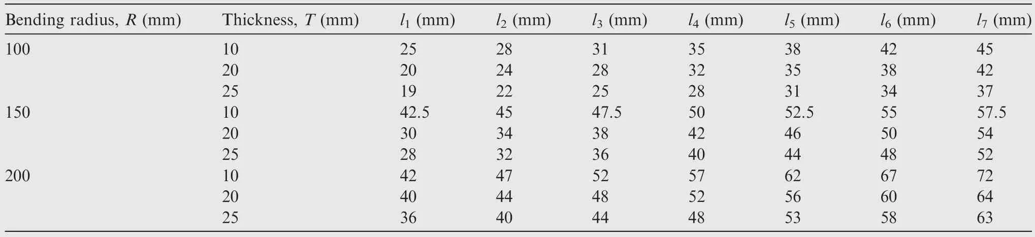
Table 2 Geometry of part continuously grooved NRH-2.7–48 honeycomb testing specimens.
To determine the appropriate grooving spacing of the honeycomb, it is necessary to study the relationships between the mechanical properties and the deformation of honeycombs after bending.Thus, we performed quasi-static out-of-plane compression tests on flat honeycomb specimens and curved honeycomb specimens in this study.The out-of-plane compression tests were performed according to ASTM standard C365,33and the details are shown in Fig.6(a).In addition,the details of the compression experiments on curved honeycombs can also be found in our previous work.24All tests were performed with a constant crosshead speed of 1 mm/min to eliminate the dynamic effect.Five replicate tests were carried out for each loading case to demonstrate the repeatability of the tests.A typical compression force–displacement curve consists of an elastic stage and a prolonged stress plateau,24as shown in Fig.6(b), and the compression strength is defined as the peak load divided by the specimen cross-section area.
Then,the relationship between the deformation of the honeycombs and their compression strength can be established,and an appropriate grooving spacing is determined by setting the tolerance for the compression strength.

Fig.6 Out-of-plane compression testing of flat honeycomb and typical compression curve.
3.3.Grooving spacing prediction method
As the actual aerospace honeycomb sandwich structures generally contain variable and continuous curvature features for smooth aerodynamic configuration and considering the limited sample data, it is critical to collect the continuous grooving parameters in terms of thickness and radius given the limited sample data.Direct application of the above experimental methods is both costly and time-consuming.Therefore,an efficient and high-fidelity surrogate capable of approximating the experimental results needs to be developed.The data-driven Gaussian Process (GP, equivalent to single-layer fully connected neural network) is generally regarded as an efficient and accurate scheme to predict the uncertainty parameters with a small amount of training data corresponding to a small sample size of uncertain parameters.34,35Thus,in this research,a GP model is established to evaluate the grooving spacing of honeycombs with different geometry parameters.
A GP is a collection of random variables, for which any finite number has a joint Gaussian distribution.A prior distribution over latent continuous functions, f(x), as shown in Fig.7,is assumed to be a Gaussian Process,and can be written as
which is defined by its mean function m(x) and the covariance function k(x, x’) with the collected data D = {X = [x1,x2,..., xn], y = [y1, y2,..., yn]}, where n is the number of data points.The input xiis d-dimensional, and d is the number of geometric feature parameters.The geometric feature parameters in this study include cell wall size, relative density, honeycomb thickness,and bending radius.Thus,d is equal to 4.The output yidenotes the grooving spacing, as yi= f(xi) + ε,where ε denotes the noise following the Gaussian distribution ε ~N(0,.We can make the standard assumption of a mean function of zero without loss of generality.For a prediction of f*(X*) at any number of points X*, the posterior distribution can be found as
where K, K*and K*,*are the simple form of the covariance matrix K(X,X), K(X,X*) and K(X*,X*), respectively; I is the n × n identity matrix.
In this work, a squared exponential covariance function is used:
where σfis a scaling term for the variance, l is a length-scale parameters vector for the d dimensions of the x input vectors,‖∙‖ is the 2-norm operator, and δ is the Kronecker delta function.
Once the mean and covariance functions are determined,the hyper-parameters(θ=[σf,l,σn])can be optimized by using the Maximum Likelihood Estimation(MLE).The natural logarithm of the marginal likelihood of the training sample is expressed as
in which G=K+σ2nI.The gradient-based optimization algorithms (e.g., conjugate gradient ascent) can be used to identify the best hyper-parameters.
4.Experiments and parameters prediction method
The previous sections outline a honeycomb grooving method and a framework that combines experiments and machine learning to predict the grooving spacing.In this section, the results of grooving parameters prediction are presented,including data collection for the GP model,model verification,and grooving angle and depth calculation.
4.1.Data collection
To collect the data of grooving spacing, it is first necessary to evaluate the deformation of honeycombs with different grooving spacing.The proposed measure of minimum principal stretch, min(λi), in Ref.23is calculated and plotted over the top surface of honeycombs.As an example, the deformation contours of the 10 mm thick NRH-2.7–48 honeycomb at a 100 mm bending radius for different grooving spacings are shown in Fig.8.The values of min(λi) that are much smaller than one indicate the collapse of honeycomb cell walls in this region.
To better characterize the deformation level of honeycombs, a statistical analysis of min(λi) values at the nodes of honeycomb cells over the top surface is performed.The distribution of the min(λi) follows a logistic distribution governed by the mean value μ and the scale parameter σ The fitted parameters μ and σ of min(λi) about 10 mm thickness NRH-2.7–48 honeycomb at a 100 mm bending radius are shown in Fig.9,where the results are plotted for various grooving spacings.Here,the horizontal axis is normalized as the ratio of the grooving spacing to the maximum grooving spacing, li/lmax,i=1,2,...,7,in the range of[0,1].It can be seen that the mean value μ of min(λi)decreases with the increase of grooving spacing, which indicates a more significant deformation level of honeycomb at larger grooving spacings.On the contrary, the scale parameter σ of min(λi) increases with grooving spacing,indicating that the honeycomb’s deformation level presents greater fluctuations at large grooving spacings.

Fig.9 Fitted parameters μ and σ of min(λi) of 10 mm thickness NRH-2.7–48 honeycomb with different grooving spacings at a 100 mm bending radius.

Fig.8 Deformation contours of 10 mm thickness NRH-2.7–48 honeycomb with different grooving spacing at 100 mm bending radius.
Furthermore, the relationship between the deformation of honeycombs and their compressive strength is established using the method from Ref.24as shown in Fig.10.Then, the grooving spacing can be determined by specifying an appropriate Compressive Strength Tolerance(CST),which is defined as the minimum allowable ratio of the compressive strength of curved honeycombs to flat honeycombs.It should be noted that a larger CST value means that the grooved honeycombs maintain good compressive strength after bending but the number of grooves is increased.As the grooves must be filled with styrofoam after bending, more grooves in this case mean that more styrofoam is needed,which will increase the mass of the part(the density of styrofoam is higher than that of honeycomb).Conversely, a smaller CST needs fewer grooves but weakens the compressive strength.In order to balance the compressive strength and the mass, the final value of CST is set at 90% according to the engineering experience.The 90%CST contour and the corresponding grooving areas are shown in Fig.10.Moreover, the deformation of the 10 mm thick NRH-2.7–48 honeycomb at a bending radius of 100 mm for various grooving spacings is plotted in Fig.10(solid black dots and connected with a curve).The final grooving spacing is determined by the intersection of the curve with the 90%CST contour.
To analyze the effects of material and geometry parameters,the grooving spacing of different types and thicknesses of honeycombs at various bending radii is shown in Fig.11.The grooving spacing increases with the increase of bending radius due to the severe deformation level of honeycombs at a smaller bending radius, and therefore more grooves are needed to release local stress.The grooving spacing drops as the honeycomb thickness increases due to the thicker honeycomb being more likely to collapse during bending.Besides, the cell size has a positive effect on the grooving spacing,while the relative density has a negative effect on the grooving spacing.

Fig.11 Effects of bending radius, honeycomb types, and thickness on grooving spacing.
4.2.GP modeling verification
In this study,90%of the data collected in Section 4.1 are randomly selected to train the GP model and the rest for validation.The testing set is used to compare the GP predictions against the experimental results.The coefficient of determination, R2, is used as an error metric and is given by
where yiis the true value, ^yiis the respective prediction of the GP,y-iis the mean of yi,and N is the total number of samples.The value R2is on the scale of[0,1],and the closer the value is to 1, the better the fit is.The training results are shown in Fig.12(a), with R2= 0.9924.The optimized hyperparameters are θ = [σf, l, σn] = [-0.0217, [5.4527, 1.5237,2.3919, 3.9208], 0.8810].In addition, the testing results of GP are presented in Fig.12(b), with R2= 0.9905.Apparently,the values predicted by the GP model match well with the experimental values, with the error less than 1%.Hence, the GP model can be applied to the grooving spacing prediction.
4.3.Grooving angle and depth
Other grooving parameters that need to be determined include grooving angle α and depth H.The bending process of grooved honeycombs is shown in Fig.13.The width of the groove, D,can be expressed in terms of the honeycomb thickness T,bending radius R, grooving spacing l, and grooving depth H as
Besides,the width of the groove after bending is denoted as d.The length of the honeycomb’s upper surface after grooving,l′, is
Without losing general assumptions, the neutral layer (the length of the neutral remains constant)of the honeycomb core is in the middle thickness during bending.Thus, the bending radius of the neutral layer is
Then,the central angle can be calculated with the grooving spacing l as
The arc length of the upper surface of the ungrooved honeycomb after bending is
and the arc length of the upper surface of the grooved honeycomb after bending is
Finally, considering the geometric relation that the ratio of the length of the honeycomb upper surface before and after bending is equal to the ratio of the width of the groove before and after bending:

Fig.12 Training and testing results for GP.

Fig.13 Schematic of grooved honeycomb bending process.
the grooving angle can be expressed as
It can be seen that the grooving angle αand depth H that govern the width of the groove after bending d are only dependent on the bending radius R and honeycomb thickness T,but not on the grooving spacing l.
5.Case analysis: Grooving parameters for an airplane fairing part
In this section, the grooving design of a honeycomb sandwich fairing part is conducted as an example to validate the proposed grooving method.The primary focus is on determining the grooving parameters.
5.1.Structural feature analysis of fairing
The structural feature of the honeycomb sandwich fairing part is analyzed first.The outer surface of the fairing part is extracted and extended based on the curvature continuity,and the curvature honeycomb of the extended outer profile is presented, as shown in Fig.14, which exhibits a symmetrical distribution.In addition, the curvature is changing continuously and is mainly distributed in the corner area, with maximum curvature of 0.012 mm-1.The thickness of the fairing part is 20 mm.
5.2.Grooving parameters determination
The grooving parameters of the fairing part are then needed to design, including the grooving spacing, angle, and depth.The detailed calculation procedure for the grooving spacing is described below, and the scheme is shown in Fig.15.
Step 1.Extract the boundary of the outer profile,and using the boundary endpoint as the starting point, search the next point pi, with step si, and read the corresponding curvature ρiand thickness Ti;
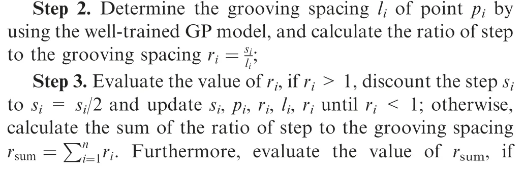

Fig.14 Structural feature of honeycomb sandwich fairing part.

Fig.15 Flowchart for determining the grooving point.

Repeat Steps 1 to 3 until the search for the outer contour boundary is complete.The results of the grooving calculations about the fairing part with the initial search step set to 5 mm are shown in Fig.17(a) (only half of the structure is shown due to symmetry).Eight grooves need to generate in total,and the corresponding grooving spacing is 474.5 mm,84.8 mm, 32.5 mm, 30.3 mm, 24.1 mm, 22.3 mm, 24.9 mm and 32 mm, respectively.The grooving traces are generated by connecting the grooving points with splines,and the process is shown as follows.36Extract the spanwise boundary of the outer profile and discrete the boundary with equivalent distance; create normal planes at discrete points and intersect it with the outer profile to create section lines, as shown in Fig.17(b); calculate grooving positions of each section lines based on the above proposed algorithm, and the results are shown in Fig.17(c);generate the grooving traces by connecting the grooving points on different section lines with splines, as shown in Fig.17(d).
For simplicity and without breaking the continuity of the honeycombs, the grooving depth is set as an experiencebased value, which is 2/3 of the honeycomb thickness, i.e.,H=2/3T.Then,the grooving angle αnof each grooving point Pnis calculated.Before calculating the grooving angle αn, the bending radius Rncorresponding to the grooving point is recorded.According to Eq.(12), the grooving angle of the eight grooves is calculated with the groove width d set to 2 mm after bending, and the resulted grooving angles are 8.6°, 8.9°, 9.1°, 9.5°, 9.9°, 9.5°, 9.2° and 9.0°, respectively.

Fig.16 Calculation for grooving spacing.
The unfolded grooved fairing part is constructed following the steps below.First,unfold the outer profile and transfer the grooving traces to the unfolded profile.Then, construct the unfolded ungrooved fairing part followed by creating Vshape sketches at the unfolded grooving points based on the calculated grooving angles.Finally, construct grooves in the unfolded fairing part based on the unfolded grooving traces and the V-shape sketches, as shown in Fig.18.
5.3.Verification
For verifying the accuracy of the predicted grooving parameters and the effectiveness of the generated grooving traces,the bending experiment of the honeycomb sandwich fairing part was conducted.The grooved flat honeycomb was first formed by ultrasonic vibration-assisted cutting based on the unfolded grooved fairing part shown in Fig.18.Then, the grooved flat honeycomb was bent to form the honeycomb fairing part, and the profiles of cells between two grooving traces were presented,as shown in Fig.19.In addition,the maximum groove width of each grooving trace after bending was measured,as presented in Fig.20.It can be seen that the local collapse of the honeycomb cell walls was not observed and the grooves were almost fully closed (the maximum groove width of each grooving trace was in the interval of tolerance, which was equal to the value of parameter d),indicating that the predicted grooving parameters are accurate, and the proposed grooving method can well eliminate the bending-reduced collapse of hexagonal honeycombs.
6.Conclusions
This paper presents a novel honeycomb grooving method for eliminating bending-induced honeycomb collapse by releasing local stresses.The validity and efficiency of the method lie in the determination of the appropriate grooving parameters.A framework built upon the experiment-based,machine learning approach is presented to perform the prediction of grooving parameters.From the results, the following conclusions can be drawn:

Fig.17 Grooving position and grooving track generation of fairing part.

Fig.18 Unfolded grooved fairing part.
(1) The continuously grooved honeycomb bending experiments combined with the deformation assessment method can effectively evaluate the effects of grooving spacing on the deformation.The deformation level of honeycombs increases with grooving spacing and exhibits larger fluctuations in large grooving spacing.
(2) A criterion for determining grooving spacing was proposed based on the relationships between the deformation of honeycombs and their compressive strength by setting a suitable tolerance for the compressive strength.Then, the grooving spacing of different honeycomb types and thicknesses at various bending radii is determined.The bending radius and cell size have a positive effect on the grooving spacing,but the thickness and relative density have a negative effect on the grooving spacing.
(3) The data-driven Gaussian Process (GP) is an efficient and accurate method for predicting the grooving spacing with a small amount of training data.The values predicted by the GP model match well with the experimental values, with the error less than 1%.Besides, the grooving angle and depth that govern the width of the grooves after bending are derived using the geometric relations of honeycomb before and after bending.
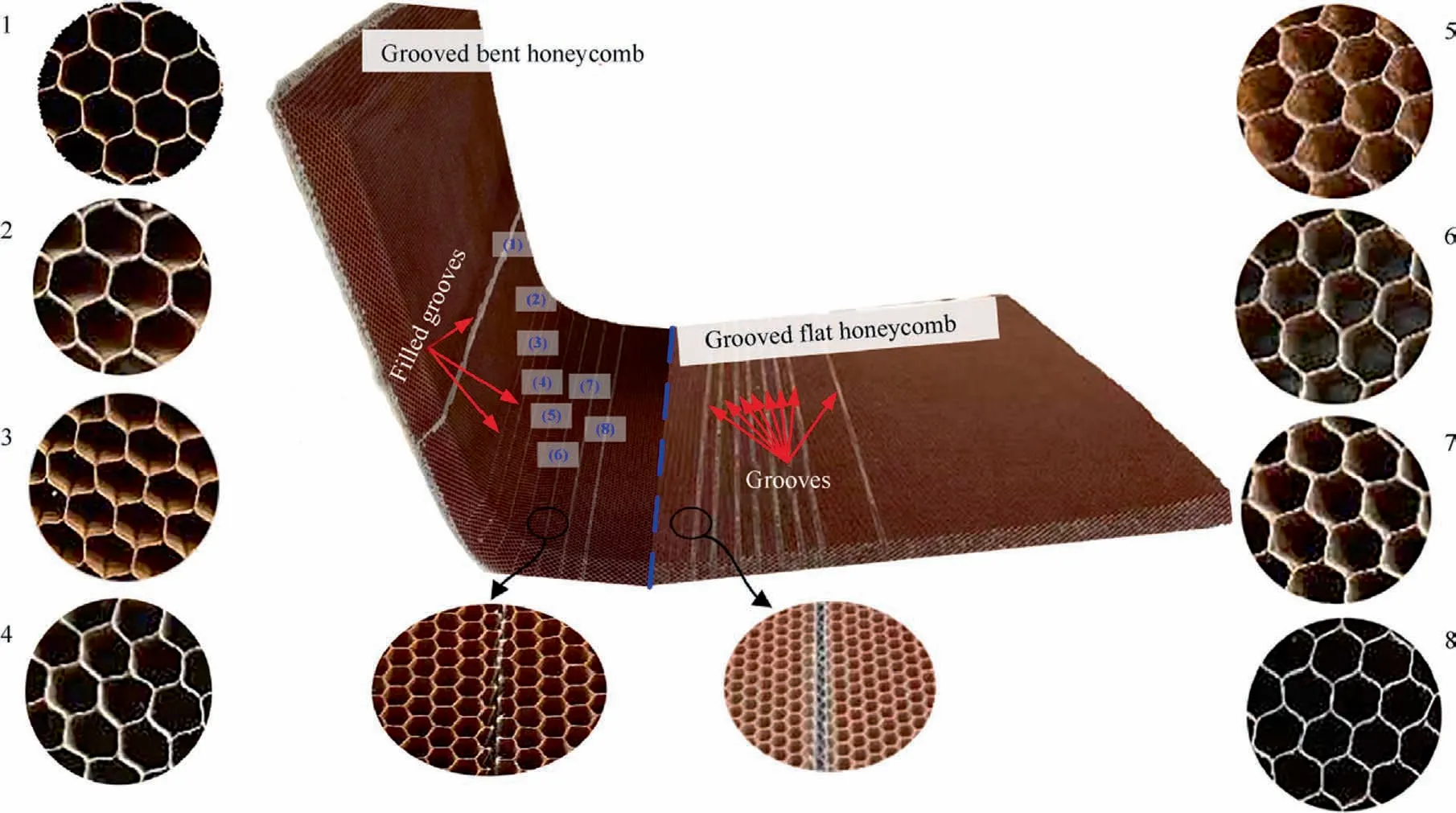
Fig.19 Honeycomb fairing part and deformed profile of cells.

Fig.20 Maximum groove width of each grooving trace after bending.
(4) In addition, the detailed design procedure and verification of the grooving parameters, including the grooving spacing and angle, for a honeycomb sandwich fairing part are conducted based on the proposed grooving method.
It is noteworthy that the study methods of this paper can be applied to different curved Nomex honeycomb sandwich structures.
Declaration of Competing Interest
The authors declare that they have no known competing financial interests or personal relationships that could have appeared to influence the work reported in this paper.
Acknowledgements
This research was supported by the National Natural Science Foundation of China (No.11902256) and the Natural Science Basic Research Program of Shaanxi,China (No.2019JQ-479).
 CHINESE JOURNAL OF AERONAUTICS2023年10期
- CHINESE JOURNAL OF AERONAUTICS的其它文章
- Experimental investigation of typical surface treatment effect on velocity fluctuations in turbulent flow around an airfoil
- Oscillation quenching and physical explanation on freeplay-based aeroelastic airfoil in transonic viscous flow
- Difference analysis in terahertz wave propagation in thermochemical nonequilibrium plasma sheath under different hypersonic vehicle shapes
- Flight control of a flying wing aircraft based on circulation control using synthetic jet actuators
- A parametric design method of nanosatellite close-range formation for on-orbit target inspection
- Bandgap formation and low-frequency structural vibration suppression for stiffened plate-type metastructure with general boundary conditions