
High-fidelity simulation of blade vortex interaction of helicopter rotor based upon TENO scheme
2023-11-10 02:18WeiBIANGuoqingZHAOXiCHENBoWANGQijunZHAO
CHINESE JOURNAL OF AERONAUTICS 2023年10期
Wei BIAN, Guoqing ZHAO, Xi CHEN, Bo WANG, Qijun ZHAO
National Key Laboratory of Rotorcraft Aeromechanics, College of Aerospace Engineering, Nanjing University of Aeronautics and Astronautics, Nanjing 210016, China
KEYWORDS
Abstract Numerical simulation methods for unsteady vortex field of helicopter rotor with high resolution and low dissipation TENO8-AA primitive variables reconstruction schemes are established based on moving-embedded grid and Navier-Stokes equations.Firstly, the Targeted Essentially Non-Oscillatory(TENO)scheme are developed by employing ENO-like candidate stencil selection strategy, and the candidate stencil is adopted with optimal weight in smooth region while it is discarded completely in discontinuous region,which reduces the dissipation and dispersion errors and approaches better spectral properties.Then,the aerodynamic characteristics of Helishape-7A model rotor in Blade Vortex Interaction(BVI)state and the flowfield of Lynx rotor in hover are simulated,which validates that the blade tip vortex trajectory with larger wake age and more details of vortex can be captured by TENO8-AA scheme with only a quarter of grid points and half time comparing to WENO-JS scheme.Moreover,the simulation accuracy of thrust coefficient is improved by up to 36%.Finally, the analyses for BVI and aeroacoustic characteristics of Operational Loads Survey(OLS) rotor are conducted, and the different forms of interaction mechanism are explored, such as oblique and parallel interactions.The results indicate that TENO scheme not only ensures the resolution of simulation in discontinuous region, but also minimizes the numerical dissipation in smooth region dominated by blade tip vortex.Therefore, the acoustic pressure peak prediction error of rotor in BVI state is significantly reduced to 5.6%and 0.8%at two microphone locations,respectively.
1.Introduction
Blade tip vortex always lingers in the vicinity of helicopter rotor.The strong tip vortex develops spirally downward and backward beneath the rotor, and might collide with the rear blade continuously,resulting in the complex flowfield.This situation will be more obvious when the helicopter is in low-speed descending flight and other special flight conditions.The tip vortex of the front blade convects in the downstream direction and then hits on the rear blade, resulting in strong Blade Vortex Interaction(BVI).1At this time,the tip vortex has a substantial impact on the overall performance of the rotor, including aerodynamic performance, noise characteristics and vibration characteristics.2Therefore,more research has been investigated on the formation and evolution of the blade tip vortex.The formation,rolling up,development and dissipation process of helicopter rotor tip vortex is very complex; as a result, secondary vortex3and tertiary vortex structures are formed, and finally the complex vortex structures are merged downstream of the trailing edge of the blade.
The rotor vortex wake can be captured and analyzed by experimental method.4However, experiments are limited in some certain rotor state due to its long period,and it is difficult to capture the whole process of vortex formation and dissipation.Various numerical methods, from the engineering-level model to the high-fidelity method, are developed at a high speed as a prediction tool for analyzing the rotor aerodynamic performance and vortex wake.The blade element momentum theory5can quickly estimate the rotor performance at a very low computational cost, but it is difficult to capture the rotor vortex field.The additional vortex wake method6–8depends on the selection of empirical parameters, and it is difficult to ensure the calculation accuracy which is limited by the experimental data and empirical parameters for rotors without test results.With the improvement of computational ability, CFD method is increasingly used to numerically simulate the flowfield of the rotor dominated by vortex.Direct Numerical Simulation (DNS)9and Large Eddy Simulation (LES)10can distinguish much detailed small-scale vortex.However, under the typical Reynolds number of helicopter flight application,DNS and LES11are proved to be very expensive due to the large number of grids, and Reynolds-Averaged Navier-Stokes (RANS) solution is a feasible choice.
Based on the RANS method, many studies on the aerodynamic performance of helicopter rotors have been carried out.The traditional 2nd-order central scheme12has a good effect on the simulation of rotor aerodynamic performance, but the ability to capture the flowfield of rotor vortex wake is relatively poor, especially in BVI state.This is mainly because the rotor vortex field usually involves multiple separated flow regions,and the large numerical dissipation of the 2nd-order scheme leads to the rapid numerical dissipation of the vortex field.Therefore,it is necessary to develop high resolution numerical schemes and adopt fine grids, which can reduce numerical errors, including dispersion and dissipation, to capture more details for flowfield analysis.Reconstructions are mainly adopted in the high order schemes,including the Finite Difference Method (FDM),13the Finite Volume Method (FVM)14and the discontinuous Finite Element Method(FEM).15Compared with the FDM, the FVM has the advantages of dealing with different types of grids and maintaining local conservation, and has been widely used in the field of helicopter rotor.The Discontinuous Galerkin (DG) method representing FEM is limited by the selection of shock limiter and artificial experience; as a result, it is rarely applied to helicopter rotors with complex conditions such as shock wave and dynamic stall.To minimize the numerical dissipation error for vortex simulation,capture the shock wave robustly and perform the simulation as efficiently as possible,a large number of low dissipation high order schemes for FVM are proposed.Liu et al.16first proposes the concept of Weighted Essentially Non-Oscillatory (WENO) high order reconstruction.On this basis,Jiang and Shu17develop the famous 5th-order WENO-JS scheme.Since then, the explosive development of various improved WENO schemes has become more and more popular, and these variants further improve the high order reconstruction performance.Henrick et al.18develop the 5thorder WENO-M method by remapping the nonlinear weights and satisfying the 5th-order accuracy at the critical point.Borges et al.19design a smooth indicator using high order global reference and develop the well-known WENO-Z scheme.Hu et al.20propose an adaptive central-upwind 6th-order WENO-CU6 scheme with improved weighting strategy.Balsara and Shu21construct a very high order WENO scheme to ensure the robustness of numerical simulations by using the technique of preserving monotonicity.Ghosh and Baeder22develop the CRWENO scheme and investigate the virtual element assignment problem of the boundary, which proves its numerical stability.Han et al.23propose an adaptive optimization WENO scheme with Gauss-Kriging reconstruction, which has the advantage of maintaining high resolution near the discontinuity and reducing the dissipation of the smooth flow region.
With the continuous development of high order schemes,many scholars adopted various WENO reconstruction schemes to calculate the vortex field of helicopter rotor.Hariharan and Sankar24adopt 5th-order and 7th-order ENO schemes with the total grid points of less than 400000 to improve the accuracy of calculation,and the numerical results of surface pressure coefficients for UH-60 helicopter rotor are in good agreement with the hovering test performed by Lorber.25However,due to the small number of grids,it is difficult to capture the details of vortex field.Xu and Weng26,27adopt the 3rd-order MUSCL and 5th-order WENO-Z reconstruction schemes to compare the numerical simulations of rotor flowfield in hover and forward flight, which proves that WENOZ scheme has higher accuracy in capturing vortex field with less numerical dissipation.Zhao et al.28introduce the CLORNS code with high order reconstruction, and the flowfield of the hovering UH-60A rotor are numerically simulated by JST scheme, Roe-MUSCL scheme and Roe-WENO scheme, respectively.The maximum wake age of tip vortex that can be captured is compared to prove the low numerical dissipation characteristics of the high order scheme.Han et al.29conduct numerical simulation on the vortex wake of hovering rotor, and find that compared with WENO-JS scheme, WENO-K scheme can capture more flowfield information of 270° vortex wake age.Jain30adopts OVERFLOW solver with 5th-order reconstruction scheme to calculate and compare the hovering performance of S-76 model-scale rotor with different grid resolutions, and it is found that with the continuous refinement of the grid, the secondary vortex and wormlike structures are more prominent,and appeared at earlier wake age.
Although WENO and other reconstruction schemes have lower dissipation than MUSCL scheme, they still produce excessive dissipation in the non-smooth regions for flowfield simulation with a wide range of temporal and spatial scales.Thus,Fu31propose a series of high order Targeted Essentially Non-Oscillatory (TENO) schemes, and the core success of TENO concept is the invention of ENO-like stencil selection strategy which either abandons the candidate stencil when it is crossed by the discontinuity or uses the optimal linear weight for final reconstruction.The TENO scheme maintains the ENO property near the discontinuity; in the meantime, compared with the conventional WENO scheme, it has lower numerical dissipation and better ability to capture shock waves in resolving the small-scale structures.To enhance the low numerical dissipation property and deal with strong discontinuity robustly, through selecting more central-upwind large candidate stencils with incremental width, TENO5-LOW31and TENO8-AA32schemes are proposed.For smooth regions,the largest candidate stencil is adopted for the final reconstruction; for non-smooth regions, lower-order candidate stencil is used.When all the large candidates are unavailable for the final reconstruction,the three small stencils are invoked.Compared with the traditional TENO scheme, TENO5-LOW and TENO8-AA schemes can control the accuracy order and the dissipation adaptively, so as to simulate the flowfield more accurately and capture more small-scale structures.
In this paper,based on CLORNS code,the unsteady vortex field of the helicopter rotor is numerically simulated by moving-embedded grid technique combined with the high order TENO5-LOW31and TENO8-AA32reconstruction schemes, and more details of the flowfield are captured compared with the WENO-JS scheme.The rest of this paper is organized as follows.Section 2 briefly introduces the governing equations and numerical schemes;Section 3 gives the introduction of the grid, the comparison of grid resolutions for Helishape-7A model rotor, and analyzes the vortex wake of Lynx rotor in hover; Section 4 gives BVI simulation of OLS rotor and discusses different forms of interaction, and then compares the BVI noise prediction results using different reconstruction schemes.Finally, a brief conclusion is given in Section 5.
2.Numerical method
2.1.Moving-embedded grid technique
To simulate the complex helicopter rotor motion, including rotational motion, periodic pitching and flapping, movingembedded grid methodology is adopted to discretize the calculation domain of rotor flowfield with O-C-O type body-fitted grid around rotor blade and Cartesian grid for the background grid.Considering the distributions of airfoils, chord length,twist and quarter-chord line,a method based on Possion equation is established to generate the blade body-fitted grid of blade, which ensures the orthogonality of the grid.Background grid is refined in the region where the tip vortex dominates, so that more details of the rotor vortex wake can be captured.In the region where the hole-cells and donor cells are located,the size of the blade grid and the background grid is reasonably distributed to match the two, so as to avoid the hole-digging error and reduce the transmission error.Taking the grid around Helishape-7A model rotor shown in Fig.1 as an example, the rotor rotation center serves as the origin of coordinate system, the +x direction points to the free stream, the +y direction points to the bottom of the rotor plane, and the + z direction is the 90° azimuth direction of the rotor.
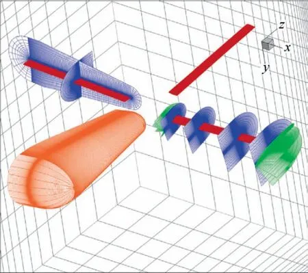
Fig.1 Computational moving-embedded grid system.
The dimensions of the blade grid are 245 (chordwise direction) × 79 (normal direction) × 150 (spanwise direction)points with leading and trailing edge spacings equal to 0.001c and 0.01c, respectively, where c is the tip chord length.Each rotor blade is composed of approximately 2.95 million grid points, and a total of 11.8 million grid points are used for four blades.The height in the first layer of the blade grid is strictly controlled,a wall spacing of 5×10⁻⁶c is set to match a dimensionless wall distance y+= 1.0, so as to meet the application of viscous non-slip boundary condition on the blade surface.The near-body blade grids are extended between two tip chord length and three tip chord length away from the surfaces with the ending spacing equals to 0.2c.In the aspect of spanwise distribution, to improve the resolution of capturing the generation of tip vortex, the tip segment is appropriately refined, and the distribution law is coarse on the root side and fine on the tip side.
In order to capture the detailed flow physics of rotor wakes,including evolution,collision,extrusion,secondary roll-up and dissipation process of the tip vortex, the background grid is reasonably refined.The far-field boundaries in the x,y,z directions are (-2.7R, 4.3R), (-1.5R, 3.0R) and (-2.7R, 2.7R),respectively, and the encryption area ranges are (-1.1R,2.8R), (-0.25R, 0.45R) and (-1.1R, 1.1R), where R is blade radius.The finest wake-grid spacing of the background grid is set to 0.12c.The dimensions of the finest background grid are 532 (x direction) × 142 (y direction) × 320 (z direction)points, leading to approximately 24.17 million grid points.Freestream boundary conditions with pressure equal to the ambient pressure and velocity equal to the forward flight velocity are applied at the far-field boundaries.
For the purpose of improving the computational efficiency of rotor flowfield simulation, the DDM method in CLORNS code28is adopted to accomplish the identification of holecells and MDSDE method is used to search donor cells,so that hole-cells can be quickly and accurately identified under the complex envelope surface and donor cells can be found efficiently.
2.2.Governing equations
The Unsteady Reynolds-averaged Navier-Stokes (URANS)method is employed as the governing equations to numerically simulate the vortex field of helicopter rotor.
where
in which U is the conservation variable,Fcand Fvrepresent the modified convective flux and viscous flux respectively.n is the unit outward normal vector to the boundary.q= [u,v,w]Trepresents the velocity components of flow in the coordinate direction, andrepresents the grid velocity vector related to the rotational motion,periodic pitching and periodic flapping.ρ,p,E,H,T,τ denote density, pressure, total energy,total enthalpy, temperature, and shear stresses, respectively.
Aimed at well simulating the separated airflow over the surface of rotor, the one-equation Spalart-Allmaras (S-A)model33is applied to simulate turbulent flows.
2.3.Spatial discretization
The solution accuracy of the convective flux has a very important influence on the simulation accuracy of the rotor vortex field.The Roe scheme34with high capture accuracy for discontinuities is adopted to discretize the convective flux, which is very robust in the simulation of the unsteady rotor vortex field.The convective flux expression on grid interface is as follows:
where subscript L and R stand for the left and right states across the cell interface.Harten ’s entropy fix method35is employed to avoid the appearance of non-physical solution.
The key to obtaining high order accuracy by using FVM is to reconstruct the primitive flowfield variables of left and right state across the cell interface.In this paper,5th-order WENOJS,175th-order low dissipation TENO5-LOW31and 8th-order TENO8-AA32with adaptive accuracy order and adaptive dissipation are adopted respectively.
2.3.1.WENO-JS
When reconstructing primitive variables on the left side of the interface, the stencil for the 5th-order WENO-JS scheme is selected as shown in Fig.2.Stencil selection on the right side of the interface can be obtained by symmetry.The reconstruction values of three candidate stencils S0,S1and S2are ^f0,i+1/2,^f1,i+1/2and ^f2,i+1/2respectively, and the left valueof the final reconstruction is as follows:
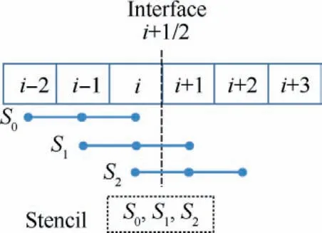
Fig.2 Schematic of 5-point stencil for WENO reconstruction(left state).
where ωkrepresents the weight of the three candidate stencils.
where ε=1×10⁻⁶is the minimum value to avoid the zero denominator.C0=0.1,C1=0.6,C2=0.3, and ISkis the smoothness indicator,which represents whether the three candidate stencils contain discontinuities.
2.3.2.TENO5-LOW
The classical WENO-JS17reconstruction performance may receive the following limitations: (A) The high order reconstruction scheme has unnecessary dissipation, and the excessive numerical dissipation in the smooth region makes the flowfield distortion polluted;(B)No universal solver is suitable for complex simulation with rich length scales.For example,when the dissipated numerical flux is beneficial to the capture of shock waves, the flow scale in the smooth region will be over-dissipated.Therefore, to solve this problem, the TENO scheme proposes an adaptive low dissipation scheme, such as the 5th-order TENO5-LOW31and the 8th-order adaptive TENO8-AA32schemes.
Unlike WENO-JS scheme, TENO5-LOW scheme has four candidate stencils, including three small three-point stencils that are the same as WENO-JS scheme and a large candidate stencil as shown in Fig.3.If the large candidate stencil is judged to be smooth for this region without discontinuity,then the largest candidate stencil is directly adopted as the final reconstruction, and the three small stencils are no longer considered.If the largest candidate stencil is judged to contain discontinuities, then adaptation within three small candidate stencils is invoked to deal with the nonlinear scale.This not only maintains the stability and accuracy of shock wave capture, but also maintains low dissipation characteristics in the smooth region, which is conducive to more accurate capture of flowfield details.This new strategy provides the flexibility to select different Riemann solvers under the unified framework,and the numerical dissipation of reconstructed flux calculation is controllable and minimized.

Fig.3 Schematic of 5-point stencil for TENO5-LOW reconstruction (left state).
In terms of the five-point scheme,the reconstructed variable at the cell interface i+1/2 can be given:
where the reconstruction^f3,i+1/2is a standard 5th-order upwind scheme.
To effectively and accurately identify smooth regions and discontinuities, the smoothness indicator is defined as follows:
where parameter C=1,q=6,ε=1×10-40, k and r denote the number of candidate stencil and stencil width respectively,βk,ris local smoothness indicator of each candidate stencil.
τKis the global reference smoothness indicator with 6thorder accuracy in smooth regions.
The smoothness indicator is normalized to detect the discontinuity, so as to determine whether the candidate stencil is involved in the reconstruction.The candidate stencil of the smooth region participates in the reconstruction of the final primitive variables with different weights, and the candidate stencil with discontinuity is removed directly.This is also an obvious difference with WENO-JS scheme.
where CTKis the cut-off parameter, which determines the recognition resolution of the discontinuity, and the value here is 10-6.
Firstly, δ3is calculated according to the four candidate stencils S0, S1, S2, S3.If the values on the left side and right side of the grid interface are both 1,which represents a smooth area,the value of the S3candidate stencil is directly used as the final reconstruction.
If any one of them is not 1, which means discontinuous, it turns to three small candidate stencils S0, S1, S2, and the final reconstruction is calculated according to their respective weights.The weights are obtained by the normalization of optimal weights dkand cutoff function δk.
where d0=0.6,d1=0.3,d2=0.1.
2.3.3.TENO8-AA
To construct a higher order reconstruction while maintaining the low dissipation characteristics of the flowfield and the computational stability of the discontinuous region, the TENO8-AA reconstruction scheme is adopted,which has the characteristics of adaptive accuracy and adaptive dissipation control.With the increase of the discontinuous strength, the number of candidate stencils is continuously reduced to maintain the stability of the discontinuous region while maximizing the calculation accuracy of the flowfield.This unique stencil selection strategy consumes a little bit more computational cost,but the calculation accuracy is greatly improved and the cost performance is very high.
As shown in Fig.4, the stencil of final reconstruction in TENO8-AA is determined in three steps.
Step 1.The largest stencil selection is S0, S1, S2and S4.When candidate stencil S4is judged as a smooth region,indicating that the group with the largest candidate stencil is smooth, candidate stencil S4is directly applied for the final reconstruction.
Step 2.If the S4candidate stencil is judged to contain discontinuities, the second largest stencil is selected, including S0,S1,S2,and S3.Then,the S3candidate stencil is checked for discontinuities, and if it is smooth, the S3candidate stencil is used for the final reconstruction.
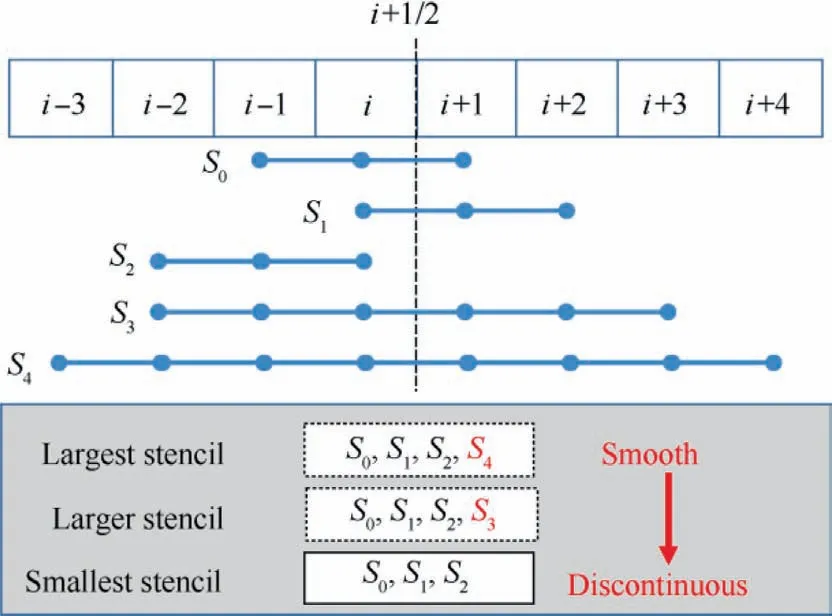
Fig.4 Schematic of 8-point stencil for TENO8-AA reconstruction (left state).
Step 3.If the S3candidate stencil is also judged to contain discontinuities, then the first three three-point candidate stencils of equal size, which are identical to those of the TENO5 scheme, are designed for final reconstruction to ensure the robust shock capturing and the lowest 5thorder accuracy.
In terms of the eight-point scheme, the reconstructed variable at cell interface i+1/2 can be written as
where the stencils for reconstruction ^f3,i+1/2and ^f4,i+1/2contain six and eight points, respectively.
An efficient scale-separation procedure which isolates the discontinuities from smooth flow scales is essentially important for robust shock-capturing and numerical accuracy improvement.The scale-separation formula γk,named smoothness indicator, is defined as
where q=7 is larger enough to achieve sufficient separation.ε=1×10-40,in which βk,ris the smoothness indicator of each candidate stencil, including three three-point small candidate stencils and the two large candidate stencils.
where the normalized smoothness indicator χkand cut-off function δkare the same as TENO5-LOW scheme.
The threshold CTKis assigned using an adaptive strategy instead of a constant parameter.If a constant parameter is adopted, the small-scale structures will not be sufficiently isolated from the discontinuity because large numerical dissipation and some smooth regions will be misjudged as discontinuous regions.
By using the discontinuity-detecting variable m based on the 1st-order undivided difference,sufficient numerical dissipation is generated for discontinuous and high wavenumber fluctuations, and CTKis dynamically adjusted according to the real-time flow scale.
where ε=1×10-40to avoid the zero denominator.To better separate the smooth region and the discontinuous region, and ensure the robustness of shock wave capture, α1,α2are set to 14 and 7, leading to that CTKranges in 10-14,10-7.
2.4.Temporal discretization
To predict the unsteady flowfield of rotor, an implicit dual time stepping method with matrix-free LU-SGS subiteration is employed to conduct the temporal discretization.Local time-stepping and Open-MP are adopted to improve the efficiency of the CLORNS code.
3.Numerical validation
3.1.Helishape-7A model rotor
Three sets of background grids are used to analyze the flowfield of Helishape-7A model rotor36related with the grid resolutions.The dimensions of coarse grid are 337 × 107 × 210 points, leading to approximately 7.57 million grid points with the minimum grid size 0.2c in encryption area;the dimensions of medium grid are 435×125×265 points,leading to approximately 14.4 million grid points with the minimum grid size 0.15c; the dimensions of fine grid are 532 × 142 × 320 points,leading to approximately 24.17 million grid points with the minimum grid size 0.12c.The blade grid is the same, whose dimensions are 245 × 79 × 150.Three schemes are employed for calculation, including WENO-JS, TENO5-LOW and TENO8-AA.
The Helishape-7A model rotor contains four blades, with chord length being 0.14 m,and aspect ratio being 15.The blade is composed of multiple airfoils and adopts piecewise linear twist distribution as shown in Fig.5.The periodic pitching and flapping angle for Helishape-7A model rotor in BVI state can be found in Ref.36.The blade-tip Mach number is 0.616, the advance ratio equals 0.167,and the rotor shaft angle is 1.48°.
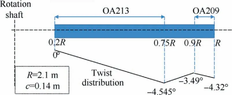
Fig.5 Definition of geometry of model Helishape-7A rotor blade.
All the simulations are performed on the workstation,possessing 40 cores of Intel Xeon Gold 6230 CPU@2.10 GHz.Four revolutions of unsteady simulation are carried out for each case, each revolution is divided into 360 physical time steps, and the sub-iteration is set to 30 to ensure the convergence.Table 1 gives the calculation time using different grids and different schemes.It can be found that compared with WENO-JS scheme, the calculation time using TENO5-LOW scheme and TENO8-AA scheme increase about 3% and 10%, respectively.
Fig.6 shows the normal force coefficients CNcalculated by different schemes and grids at the spanwise positions r/R=0.92 and r/R=0.98.It can be seen that the normal force coefficients calculated by the three schemes are almost the same and in good agreement with the experimental values.
Table 2 shows the comparison of thrust coefficient CT.It can be seen that the difference of the calculated thrust coefficients of the three sets of grids is extremely small under different schemes, indicating that the thrust of rotor has little effect on the aerodynamic force after reaching the sufficient grid resolution.
Fig.7 shows the comparison of pressure coefficients between calculated data by different schemes and experimental data using the fine grid at different spanwise positions (r/R = 0.7, 0.82, 0.92, 0.98) with 90° azimuth.It can be found from the calculated results at r/R = 0.82 that TENO8-AA is more accurate in capturing the peak of negative pressure near the leading edge at the suction surface, which indicates the TENO8-AA scheme has the lowest numerical dissipation on capturing the peak of pressure.Under the condition of paying 10% additional computational cost, the calculation accuracy of the negative pressure peak is significantly improved.
Fig.8 gives the comparison of the iso-surfaces with Qcriterion (q = 0.00025) colored by vorticity magnitude at 360° azimuth using different grids and different schemes.It can be seen that with the improvement of grid resolution,more details of vortex wake are captured; as the numerical dissipation of the scheme decreases, more abundant vortex wake structures can be captured.It is worth noting that the results of TENO8-AA scheme using coarse grid are better than the results of WENO-JS scheme using fine grid, and the computational times are 47.4 h and 84.6 h, respectively.The structure of the vortex wake captured by the TENO8-AA scheme is clearer while requiring less calculation time,demonstrating the necessity of the application of high order numerical scheme in the flowfield of helicopter rotor vortex wake.

Table 1 Comparison of calculation time using different grids and different schemes.
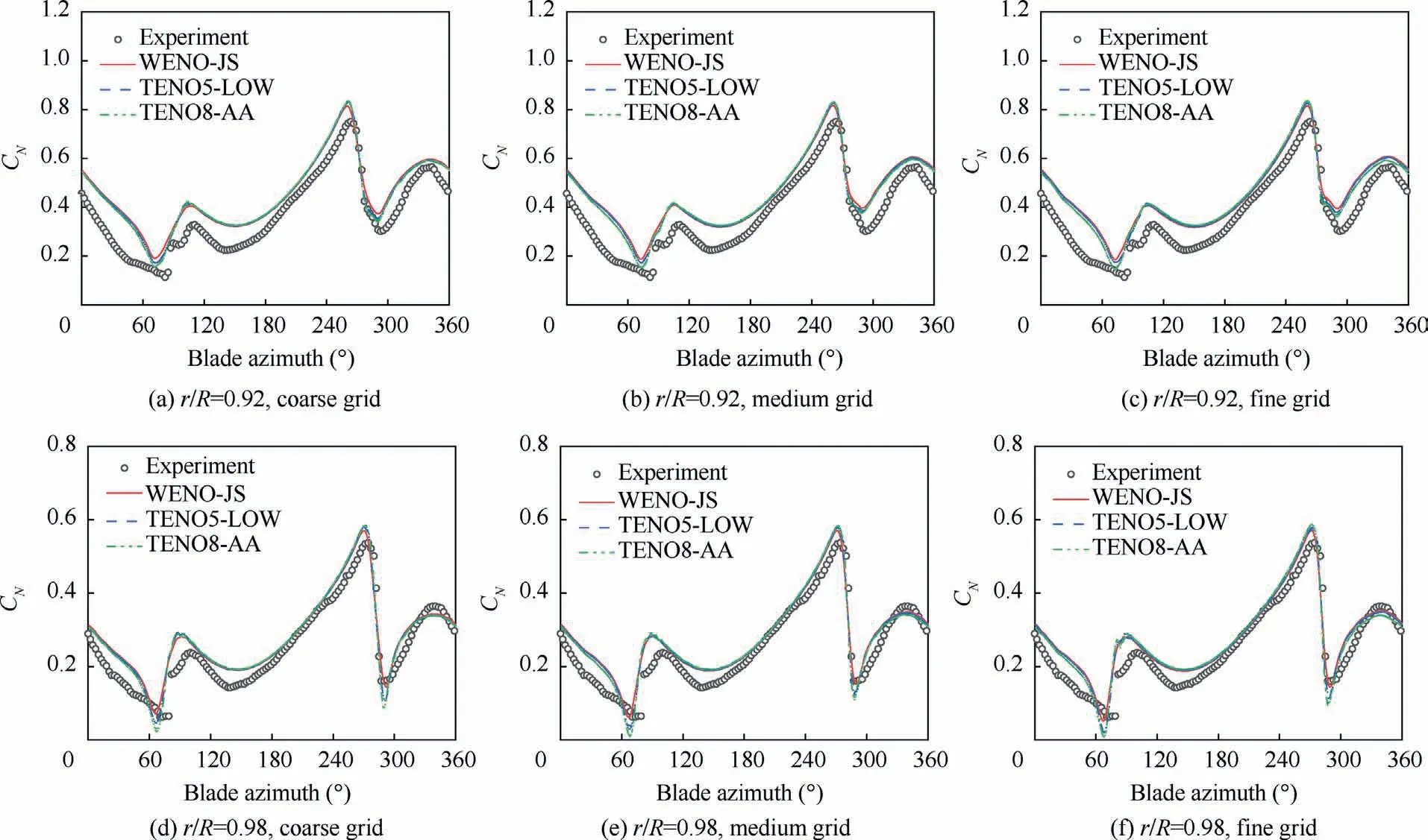
Fig.6 Comparison of normal force coefficients between calculation and experiment.
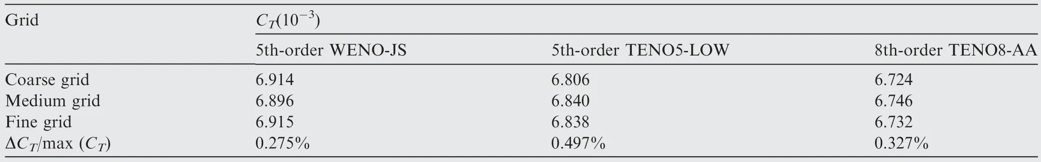
Table 2 Comparison of calculated thrust coefficient using different grids and different schemes.
3.2.Vortex wake of Lynx rotor in hover
The flowfield of Lynx rotor37in hover was tested at the Outdoor Aerodynamic Research Facility at NASA Ames Research Center, and is simulated by the numerical method introduced before.Lynx rotor is composed of four blades with NPL9615 airfoil and characterized by a rectangular platform with zero twist.The radius is 1.105 m and chord length is 0.18 m, leading to an aspect ratio of 6.139.The solidity of rotor is 0.208 with a blade root-cut at 0.384R.The rotor operates at the following condition: blade-tip Mach number Matip= 0.56, pitch angle θ = 17° and Reynolds number Re=2.31×10⁶.The dimensions of the blade grid and background grid are 245 × 79 × 150, 121 × 196 × 150 points,respectively.A comparative study is carried out by adopting the 5th-order WENO-JS scheme, 5th-order TENO5-LOW scheme and 8th-order TENO8-AA scheme respectively.
Fig.9 shows the iso-surface of Q-criterion (q = 0.35) colored by vorticity magnitude.It can be seen that with the improvement of the accuracy of the scheme,the numerical dissipation decreases, the more the vortex trajectories captured.Obviously, the strength of the tip vortex captured by the TENO8-AA scheme is higher than that of the other two schemes.
Table 3 gives the comparison of calculation time and thrust coefficients/solidity, the calculation error is significantly reduced and the accuracy is improved by up to 36% while the additional calculation time is not more than 10%, which proves that not only the rotor vortex wake is more precise,but also the simulated aerodynamic loads are more accurate by using higher order scheme.
The vorticity comparison on the cutting plane(x-y plane)is shown in Fig.10.It is obvious that the tip vortices and the structure of vortex core captured by the TENO scheme are clearer, and its strength is also greater than that of the WENO-JS scheme due to the low numerical dissipation.The overall details of the flowfield are more abundant.
Fig.11 shows the trajectory of the radial and axial positions of the vortex core.It can be found that the trajectory of the vortex core position is not so smooth, which is also close to the actual situation.The descent rate is constant up to 90°,and the axial descent rate increases after that, and then remains a stable descent rate.The simulation of axial position of the three schemes is roughly the same, which is close to the experimental value.In the radial direction,with the increase of the vortex age, the tip vortex gradually shrinks, and after approximate 300°,tip vortex begins to expand outside rapidly.The trend of radial position is well simulated by three schemes.However,compared with the WENO-JS scheme,the trajectory of vortex core including contraction and expansion in radial direction captured by the TENO scheme is more consistent with the experiment.
4.BVI analyses
4.1.BVI simulation of OLS rotor
Blade vortex interaction occurs when the helicopter is in lowspeed descending flight, which causes the sudden change of aerodynamic loads,and further leads to the vibration of blade and large BVI aerodynamic noise; therefore,the accurate simulation of BVI is essential to rotor aerodynamics.Unlike coaxial rotors or multi-rotors, single-rotor helicopters have only one rotor to provide lift, so as to balance the gravity of the helicopter.Therefore, it can be anticipated that the induced velocity of single-rotor helicopters is relatively larger,resulting in a greater convection velocity of vortex in the vertical direction.As a result, the blade-tip vortices shed from the front blade will interact with the surface of the rear blade, leading to sudden pressure pulses.The accurate simulation of blade tip vortex is the prerequisite of the analysis on BVI.
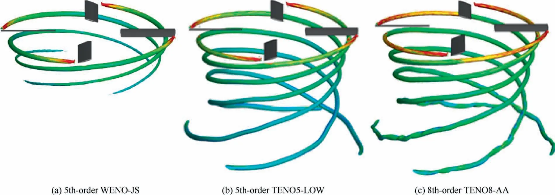
Fig.9 Comparison of tip vortex for Lynx rotor in hover.
In this section,the BVI of the 1/7 scaled model rotor(OLS rotor) of the AH-1G helicopter is simulated and analyzed using the TENO8-AA scheme.The OLS model rotor contains two rectangular blades with a radius of 0.958 m and a chord length of 0.1039 m.The blade is constructed by a single OLS airfoil (modified by BHT 540).The linear negative twist is 10° with 0.182R blade root-cut.The typical 10014 test case38is selected, which is in BVI state.The blade-tip Mach numberis 0.664,the advance ratio is set to 0.164,and the experimental thrust coefficient is 0.0054.Tip-path plane angle is tilted back by 1°due to the longitudinal flapping.The dimensions of blade grid and background grid are 245 × 79 × 150 and 452 ×142 × 290, respectively.The periodic pitching and flapping angle in BVI state are as follows.

Table 3 Comparison of calculation time and thrust coefficients/solidity for Lynx rotor in hover using different schemes.

Fig.10 Comparison of tip vortices on cutting plane (x-y plane) colored by vorticity magnitude.
Fig.12 shows the polar contours of normal force coefficient CNand azimuthal derivative of normal force coefficient dCN/dψ.It can be seen that there are sudden changes induced by interactions between tip vortices and blade surface in close proximity at five BVI regions of the dCN/dψ polar counters,as shown in Fig.12(b)(A,B,C,D,E).On the advancing side,impulsive BVI named as the oblique interaction occurs in Region A near 60° azimuth, and approximate direct interaction occurs in Region B near 90° azimuth.On the retreating side,oblique interaction occurs in Region C near 270°azimuth and serious parallel interaction between tip vortices and the blade surface occurs in Region D near 300° azimuth.Besides tip vortex BVI events, in region E located at the blade root region, the root-induced BVI events can also be seen near 10° azimuth, which is slightly different from the actual situation because the simulation does not consider the influence of the hub.
Fig.13 shows the normal force coefficient and azimuthal derivative of normal force coefficient at different spanwise positions, r/R = 0.7, 0.8, 0.91, 0.955, which is an indicator of the impulsive change of airloads.It can be seen that the blade loads change smoothly out of the BVI regions, while in BVI regions, the aerodynamic loads increase or decrease rapidly due to the pressure pulses induced by the interaction between tip vortices and blade surface.Therefore, accurate capture of the BVI is crucial to the simulation of the rotor aerodynamic characteristics.
In Region A, Fig.14 illustrates the iso-surface of a nondimensional Q-criterion (q = 0.0005) colored by vorticity magnitude near 60° azimuth.It can be seen that with the increase of azimuth, the peak position of dCN/dψ moves towards the blade root,which means that the interaction position of BVI is closer to the blade root, which is caused by the superposition of blade rotating motion (forward motion) and tip vortex backward motion (forward flight direction).Since the collective pitch angle of the retreating side is higher than that of the advancing side,which could result in higher tip vortex intensity (highlighted in darker red colors).Fig.15 shows the trailing vortices at 62° azimuth on the advancing side.It can be seen that the tip vortices of this blade in the last revolution convect in the downstream direction and below the blade, resulting in the oblique interaction.Due to the rotating motion of the blade and the influence of the tip vortex on the spanwise flow in the direction of the blade root on the lower surface of the blade, the Coriolis force is generated, and the airflow on the lower surface of the blade is decelerated in the chordwise direction.As a result, the pressure of the blade section increases due to the induction of vortex convection as shown in Fig.16, leading to an additional increase in the normal force coefficient instantaneously and a sudden increase in the aerodynamic loads.
In Region B, Fig.17 shows that the tip vortex directly impinges on the blade surface, which yields impulse BVI.It can be seen that with the increase of azimuth,the peak position of the normal force derivative is also shifted towards the blade root, same as the BVI in Region A.Fig.18 shows the interaction position between the tip vortices and blade surface at four different azimuths.It can be found that the tip vortices of the front blade convect in the downstream direction and above the rear blade, causing the approximate direct interaction.Due to the rotating motion of the blade and the influence of the tip vortex on the spanwise flow in the direction of the blade tip on the upper surface of the blade,the generated Coriolis force accelerates and the airflow on the upper surface of the blade in the chordwise direction.As shown in Fig.19, because of the induction effect of the blade tip vortex on the upper surface of the blade, the upper surface pressure of the blade sections decreases(the negative pressure increases),leading to the additional increase of the normal force coefficient and a sudden increase in the aerodynamic loads.
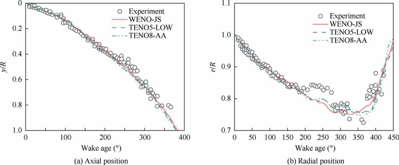
Fig.11 Comparison of axial position and radial position of tip vortex core.
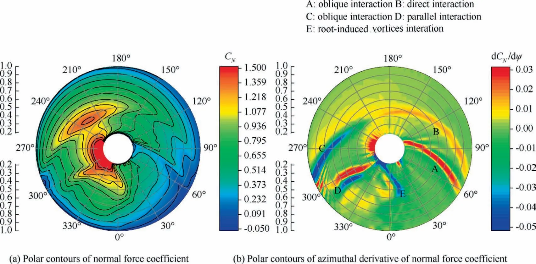
Fig.12 Polar contours of normal force coefficient and azimuthal derivative of normal force coefficient of OLS rotor of BVI state.
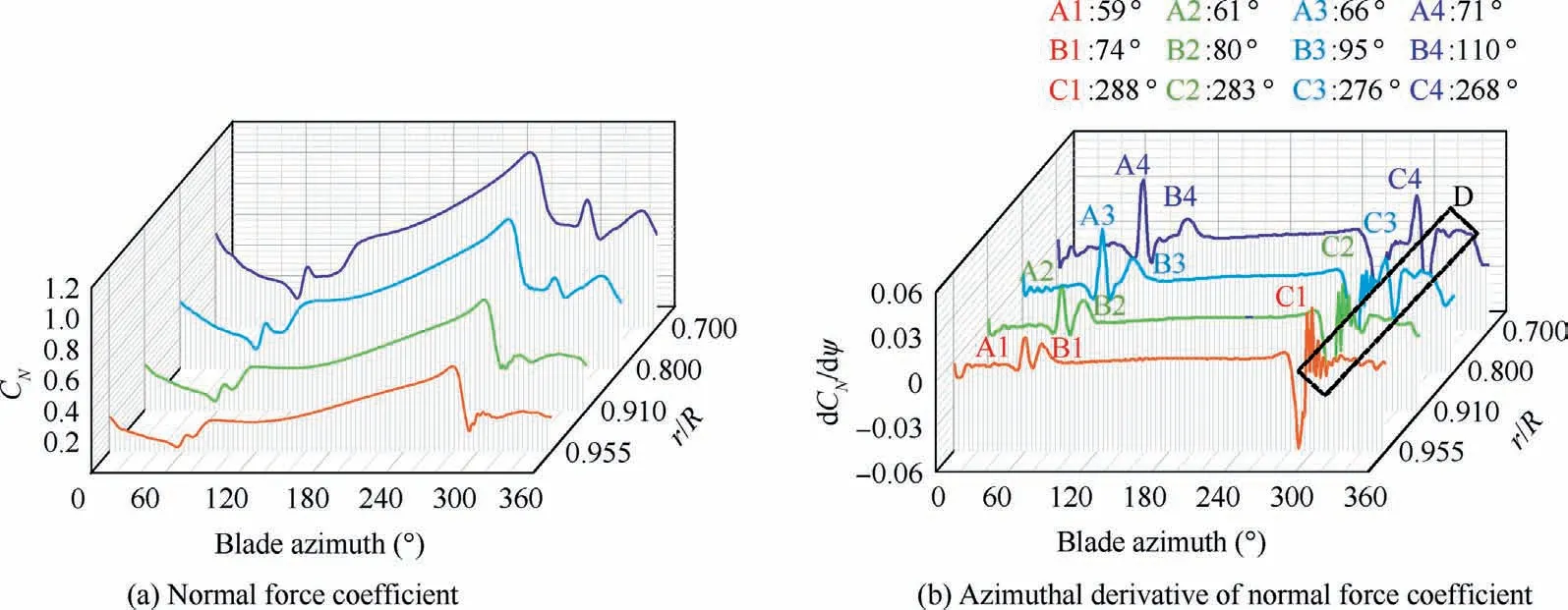
Fig.13 Normal force coefficient and azimuthal derivative of normal force coefficient at different spanwise positions.
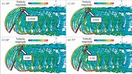
Fig.14 Iso-surfaces of Q-criterion (q = 0.0005) colored by vorticity magnitude at different azimuths in Region A.
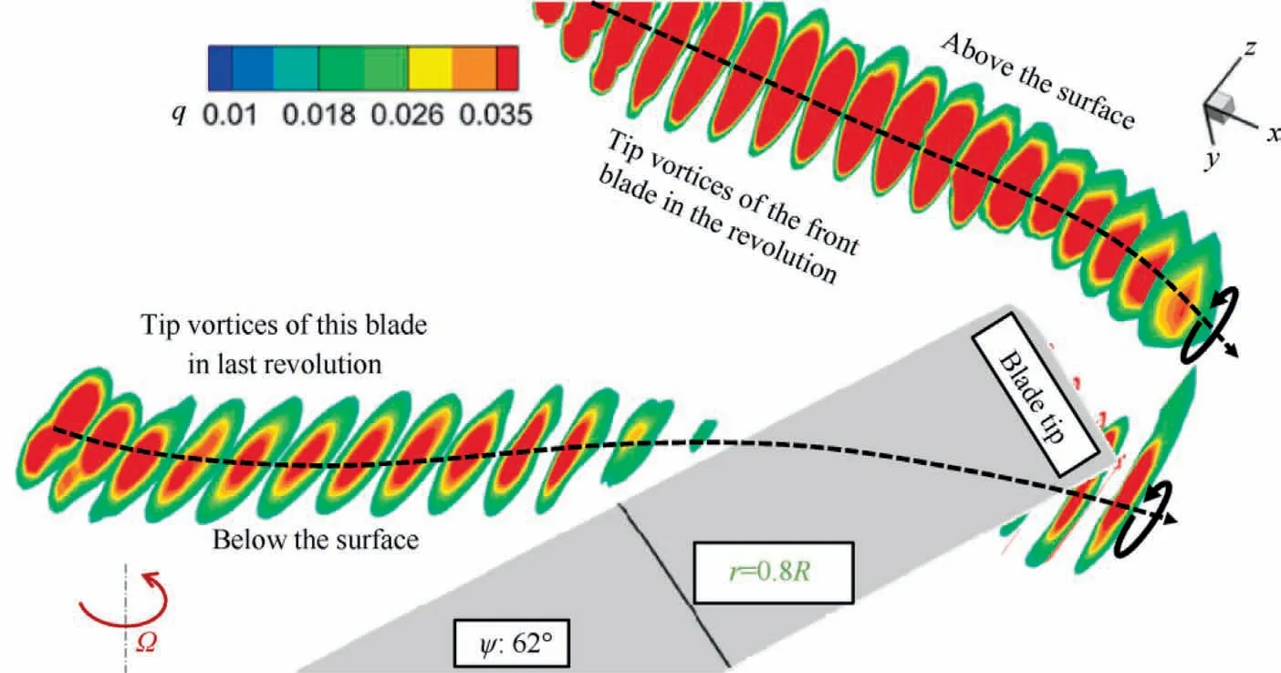
Fig.15 Tip vortices at 62° azimuth on advancing side.
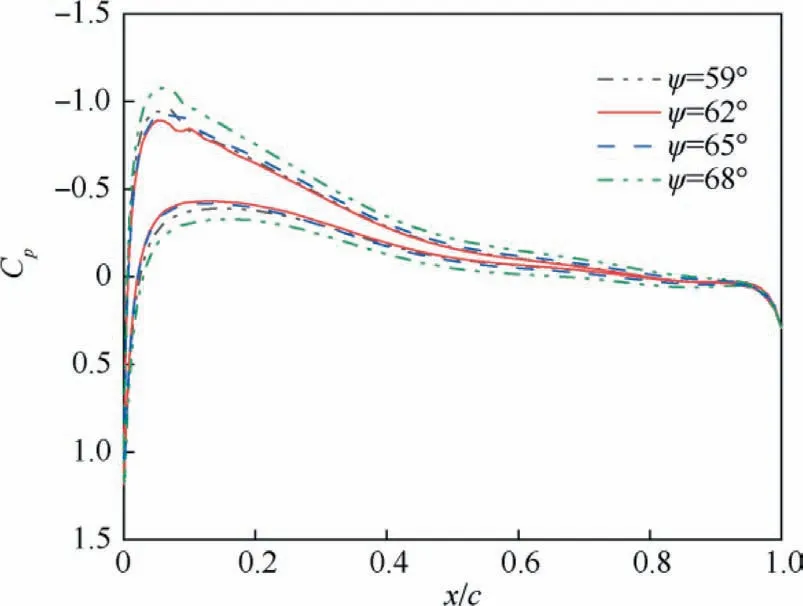
Fig.16 Pressure coefficient distribution of blade-cross section r/R = 0.8 in Region A.

Fig.17 Iso-surfaces of Q-criterion (q = 0.0005) colored by vorticity magnitude at different azimuths in Region B.

Fig.18 Tip vortices at different azimuths on advancing side.

Fig.19 Pressure coefficient distribution of blade-cross section at r/R = 0.8 in Region B.
In Region C, as shown in Fig.20, a BVI event near ψ = 270° is also found on the retreating side of the rotor.However, different from the advancing side, the position of BVI between 240° and 300° azimuths is shifted towards blade tip with the increase of azimuth,which is caused by the differential value of the blade rotating motion (backward motion)and the forward flight motion.Due to the large pitching and flapping angle near 270° azimuth, on the one hand, the strength of the tip vortex is large;on the other hand,as shown in Fig.21,when the BVI occurs,the trailing vortices shed from the front blade in the revolution impinges the leading edge of the blade, and then passes through the blade.The upper and lower surfaces of the blade are seriously interacted because of the close proximity in vertical direction between the tip vortices and blade surface.The tip vortices cause the spanwise flow in the direction of the blade root on the upper surface of the blade and the spanwise flow in the direction of the blade tip on the lower surface of the blade.The Coriolis force is generated by the superposition of the rotating motion of the blade,so that the airflow is slowed down on the upper surface, and accelerated on the lower surface in the chordwise direction.As shown in Fig.22, the pressure on the upper surface increases (the negative pressure decreases), and the pressure on the lower surface decreases, resulting in the decrease of the normal force coefficient and a large negative peak of the normal force coefficient derivative.
In Region D,as shown in Fig.23,a serious parallel interaction is found near 300° azimuth, which is different from the previous oblique interaction and direct interaction.The tip vortex is parallel with respect to the blade span,which can lead to highly impulsive noise.There is a significant increase in the normal force coefficient when the blade is about to pass the parallel tip vortex and after passing through the parallel tip vortex, the normal force coefficient has a sharp decrease.This is because the parallel interaction mainly affects the chordwise flow near the blade surface, similar to the influence process of the vortex passing through the two-dimensional airfoil.When the tip vortices are about to collide with the leading edge of the blade,it will bring a sudden increase in the normal force of the blade.As the vortices move to the trailing edge of the blade,the vortices gradually leave the blade.Because the pitching and flapping angle are also increasing at the same time,the distance between the vortex and the blade surface is also increasing, which will lead to the decrease of the normal force.Since most of the spanwise positions of the rotor blade are influenced by the parallel interaction at the same time,it has a serious impact on the aerodynamic performance, noise level and vibration characteristics of the blade.
4.2.BVI noise of OLS rotor
Farassat’s Formulation 1A39based on the FW-H equations40acoustic analogy is employed to predict the BVI noise.The aerodynamic results simulated by CFD method are used as the input of the CLORNS noise prediction codes.41The effects of different reconstructed schemes on the noise prediction accuracy are compared and analyzed, and the microphone locations are shown in Fig.24.Acoustic pressure time history is predicted at microphone 3 and 9 located below the rotor plane.
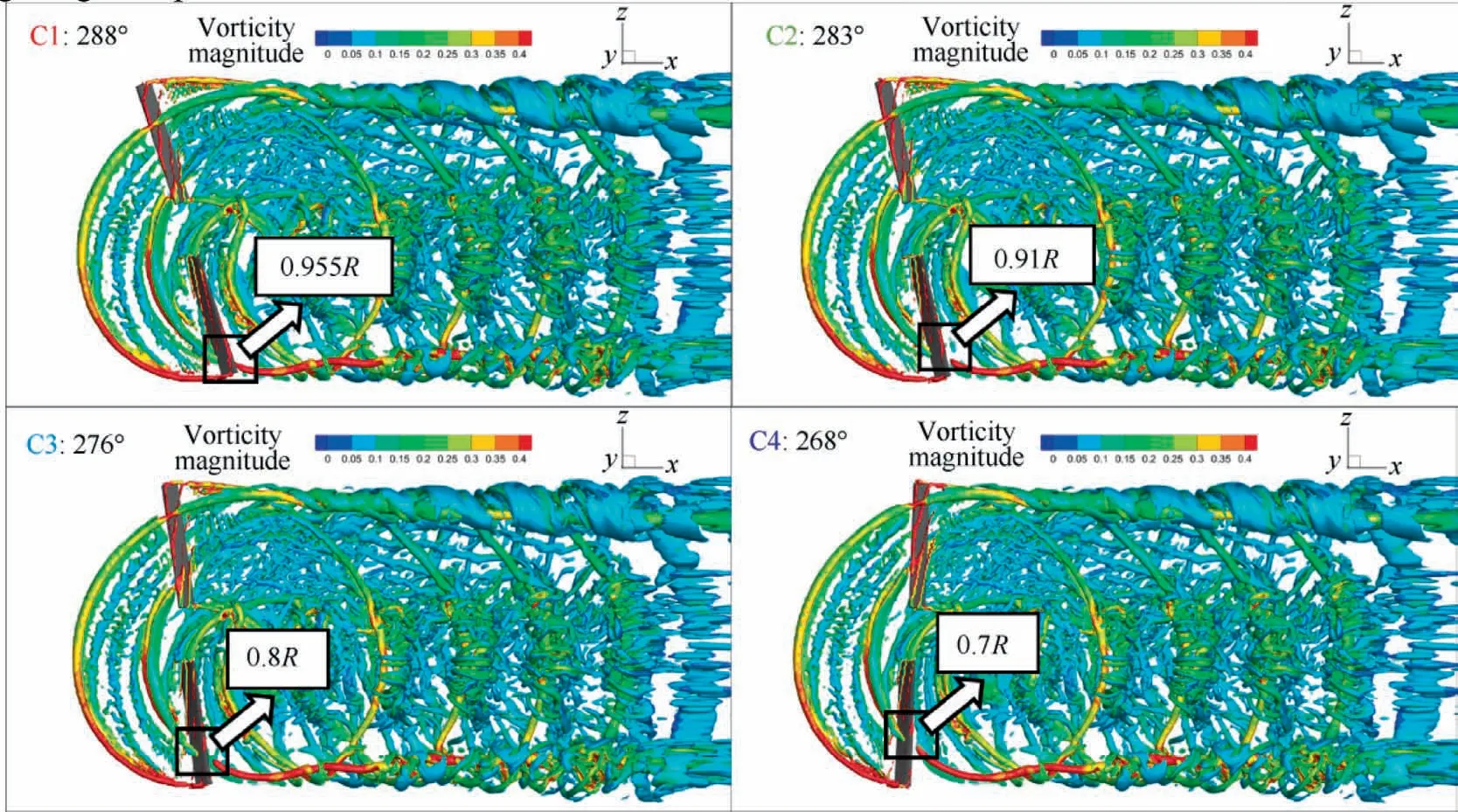
Fig.20 Iso-surfaces of Q-criterion (q = 0.0005) colored by vorticity magnitude at different azimuths in Region C.
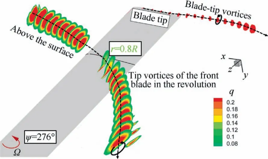
Fig.21 Tip vortices at 276° azimuth on the retreating side.
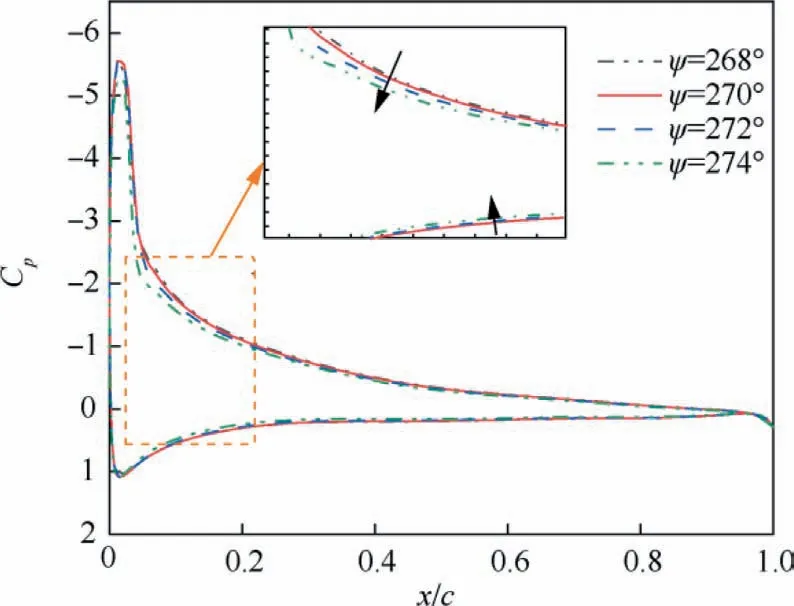
Fig.22 Pressure coefficient distribution of blade-cross section at r/R = 0.8 in Region C.

Fig.23 Iso-surfaces of Q-criterion value and trailing vortices on retreating side (parallel interaction).
Fig.25 shows that the trends of acoustic pressure time history predicted by the three schemes are similar to the experiment at microphone 3 and 9, but it is obvious that the prediction accuracy of TENO8-AA scheme is much higher than that of the other two schemes in terms of the peak of acoustic pressure.At microphone 3,the peak is over estimated by using the two 5th-order schemes, compared with TENO5-LOW scheme, the prediction accuracy of TENO8-AA scheme for the peak of acoustic pressure is greatly improved, and the prediction error is reduced from 19.9% to 5.6%.While at microphone 9, the peak prediction is insufficient, compared with WENO-JS scheme, the prediction error is reduced from 12.6%to 0.8%.According to the predicted results,in general,TENO8-AA scheme is the best, followed by TENO5-LOW scheme, which is also similar to the prediction accuracy of aerodynamic loads,indicating that reducing the numerical dissipation is conducive to the prediction of aerodynamic loads,and the detail capturing for flowfield, so as to improve the accuracy of noise prediction.
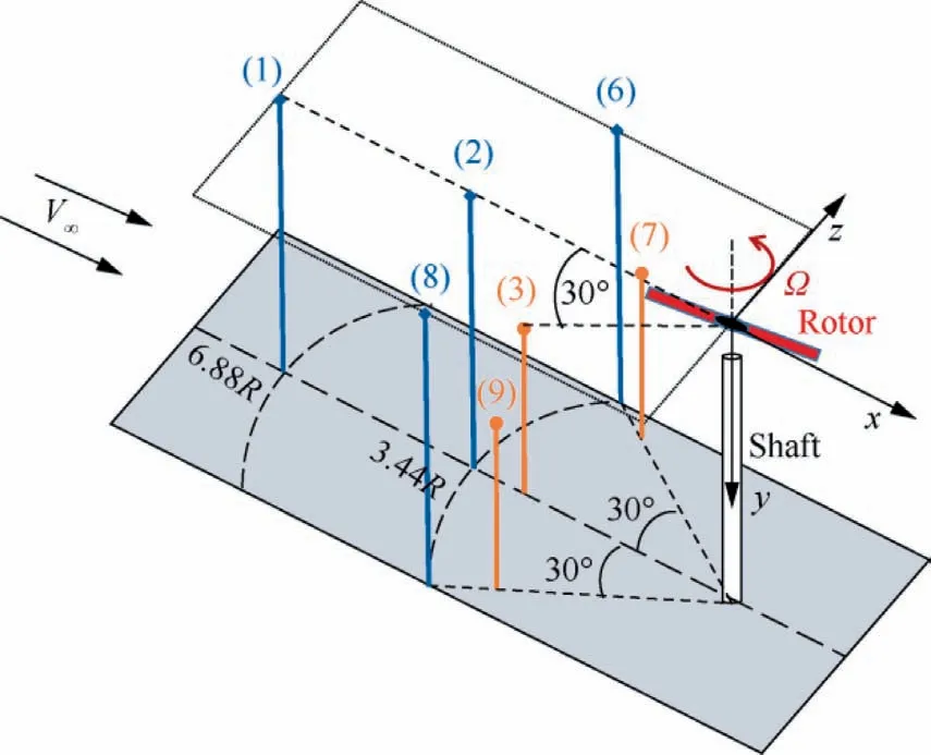
Fig.24 Microphone locations in noise experiment.
5.Conclusions
(1) Based on moving-embedded grid and high order reconstruction scheme including WENO-JS scheme, TENO5-LOW scheme and TENO8-AA scheme,a numerical simulation method with high resolution and low dissipation is established to calculate the unsteady flowfield of helicopter rotors dominated by tip vortex.
(2) The flowfield of Helishape-7A model rotor in forward flight is analyzed, the simulation results demonstrate that compared with the other two reconstructed schemes, TENO8-AA scheme can effectively capture more details of the vortex field and achieve more accurate aerodynamic loads.In addition, the results calculated by TENO8-AA scheme with coarse grids are better than those by WENO-JS scheme with fine grids,and the computational time is reduced from 84.6 h to 47.4 h.Comparing the results of the Lynx rotor flowfield in hover shows that the tip vortex trajectory with larger wake age is captured by adopting the higher order reconstruction scheme, and the radial and axial positions of tip vortex core captured by TENO scheme are more consistent with the experiment.Compared with WENO-JS scheme, TENO8-AA scheme achieves about 36% improvement on accuracy of rotor thrust prediction.
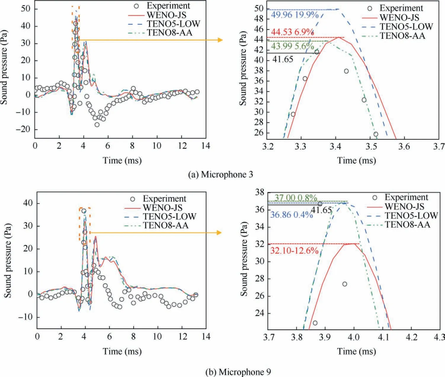
Fig.25 Predicted and experimental acoustic pressure time history for OLS rotor BVI case.
(3) In one period of rotor rotation, several different forms of BVI events will occur on the OLS rotor, including oblique and parallel interactions, which will cause sudden changes in the aerodynamic loads and the generation of BVI noise.On the advancing side, impulsive BVI named as the oblique interaction occurs near 60°azimuth,and approximate direct interaction occurs near 90° azimuth.On the retreating side, oblique interaction occurs near 270° azimuth and serious parallel interaction between tip vortices and the blade surface occurs near 300° azimuth.From the comparison of BVI noise prediction results using the three schemes, it can be found that the high order TENO8-AA scheme with low numerical dissipation can capture more abundant details of rotor vortex field, so that the peak of acoustic pressure can be predicted more accurately, and the prediction error is reduced from 12.6% to 0.8% at microphone 9.
Declaration of Competing Interest
The authors declare that they have no known competing financial interests or personal relationships that could have appeared to influence the work reported in this paper.
Acknowledgements
This study was co-supported by the National Natural Science Foundation of China(Nos.12032012,12072156),the National Key Laboratory Foundation of China(No.61422202103),and the Priority Academic Program Development of Jiangsu Higher Education Institutions, China (PAPD).
 CHINESE JOURNAL OF AERONAUTICS2023年10期
- CHINESE JOURNAL OF AERONAUTICS的其它文章
- Experimental investigation of typical surface treatment effect on velocity fluctuations in turbulent flow around an airfoil
- Oscillation quenching and physical explanation on freeplay-based aeroelastic airfoil in transonic viscous flow
- Difference analysis in terahertz wave propagation in thermochemical nonequilibrium plasma sheath under different hypersonic vehicle shapes
- Flight control of a flying wing aircraft based on circulation control using synthetic jet actuators
- A parametric design method of nanosatellite close-range formation for on-orbit target inspection
- Bandgap formation and low-frequency structural vibration suppression for stiffened plate-type metastructure with general boundary conditions