
Electromagnetic interference modeling and elimination for a solar/hydrogen hybrid powered small-scale UAV
2023-11-10 02:16JiahaoGELiLIU
CHINESE JOURNAL OF AERONAUTICS 2023年10期
Jiahao GE, Li LIU
School of Aerospace Engineering, Beijing Institute of Technology, Beijing 100081, China
KEYWORDS
Abstract The trajectory related and Direct Current (DC) Electromagnetic Interference (EMI) of lithium battery, fuel cell and photovoltaic modules has a great influence on the small-scale Unmanned Aerial Vehicle (UAV) airborne magnetometer and is hard to be shielded, calibrated or filtered.Besides, the mechanisms underlying the DC EMI have been rarely investigated yet.To cope with this problem, this paper systematically studies the EMI models, and proposes an online 3-layer EMI reduction scheme.First, EMI coupled with UAV motion model and hybrid power system is established.Second,the mechanism EMI models of hybrid power system are established and verified based on the proposed concept ‘‘equivalent current”.Third, an online 3-layer EMI reduction scheme is proposed, including battery layer, trajectory planning layer and energy management layer.In the first main layer,EMI self-cancellation is realized by rotating battery inclinations and symmetrical circuits.In response to errors, the trajectory planning layer reduces the EMI intensity by optimizing an optimal trajectory, while the energy management layer prioritizes power allocation to power sources that can produce small and stable EMI.Simulation results of climb,level flight and descent illustrate the efficaciousness and applicability of the proposed online 3-layer EMI reduction scheme.
1.Introduction
The utilization of solar/hydrogen hybrid power, including lithium battery, Proton Exchange Membrane Fuel Cell(PEMFC) and Photovoltaic (PV) modules, enables longendurance UAVs to maintain small scale and fly at lower altitude rather than near space, and to endure multiple weather conditions.1However, the narrow cabin is crowded with various electronic equipment and hybrid power supplies,which produces more complex and stronger EMI than the UAVs powered by conventional or single energy.EMI will affect the weak signal measurement of geomagnetic field2,3by airborne magnetometer,which leads to heading deviation.4Furthermore,the continuous EMI will even lead to positioning error, velocity drift and attitude calculation error.Therefore,reducing EMI is an eternal theme for the safety flight of electric powered UAVs.
The EMI of a small-scale hybrid powered UAV covers a wide range of frequencies.For the sake of pertinent EMI elimination, this paper proposes an EMI classification criterion:the EMI at airborne magnetometer is divided into trajectory related and unrelated parts.The former is mainly highfrequency EMI,which is generated by,for example,switch circuits,Brush-Less Direct Current(BLDC)motors,etc.The latter is mainly low frequency and DC EMI produced by DC current of powertrain, which varies with actual flight power.The traditional means of reducing EMI at magnetometer include (A) shielding EMI sources and cutting off coupling approaches, such as spraying conductive paint,5twisting the wires in pairs,utilization of electromagnetic shielding devices,6etc.;(B)EMI suppression circuit,such as electrical grounding,7adopting various filters,8,9etc.; (C) calibration10–12before flight.
However, the traditional schemes have limited effect and fail to fully eliminate the impact of EMI.For the trajectory unrelated EMI, low-pass filters can eliminate most of its impact,13which have been proved to perform well in engineering practice.For the trajectory related EMI, firstly, it is hard to be shielded due to its DC characteristic.Besides,shielding devices will bring about the problem of extra weight and heat dissipation, let alone wrap the PV modules and magnetometer itself.Secondly, it is also hard to be filtered due to its similar frequency with geomagnetic field.14However, the calibration algorithms must be carried out before the UAV takes off, usually when the avionics works but the output current of powertrain does not change.Both deviation calibration and filtering algorithms are hard to deal with the time-varying EMI during flight, because they usually treat EMI as a bias vector, ignoring the electromagnetic characteristics.8,9In order to eliminate the trajectory related EMI, it is further divided into mutually eliminable EMI, such as that generated by twisted paired currentconducting wires, and non-mutually eliminable EMI of power sources, i.e., lithium battery, PEMFC, and PV modules.The trajectory related non-mutually eliminable DC EMI is the main object of this paper.Nevertheless, there have been few models to picture the EMI of hybrid power sources, which makes it difficult to be eliminated accurately and manage the power distribution reasonably according to their electromagnetic characteristics.
An optimal trajectory can reduce the EMI at magnetometer due to the correlation between the non-mutually eliminable DC EMI and trajectories.14As a matter of fact, according to Biot-Savart law,reducing the flight required power can reduce the current of powertrain, and then reduce the EMI intensity.In the facet of trajectory optimization, the motion of UAV is described by a set of complex nonlinear equations with multiple variables and constraints.There are plenty of algorithms,such as pseudo-spectral methods,15–17sample based methods,18convex optimization,19,20optimal control,21etc.Among various algorithms, hp-adaptive Radau pseudo-spectral method22is widely adopted in trajectory optimization problem due to its fast convergence in solving complex nonlinear optimization problems.
!In accordance with the above analysis, different from the traditional EMI reduction methods, some exploratory but systematic work has been done.The innovations and main contributions are presented in the following aspects.
(1) According to mechanism analysis,23the concept of‘‘equivalent current” is proposed to reveal the relationship between redox reactions and photovoltaic effect and macroscopic EMI.Then the EMI mechanism models of lithium battery, PEMFC and PV modules are established and identified or verified by experiments.
(2) An online 3-layer EMI reduction scheme is designed.The first main layer reduces EMI through closed-form battery inclinations adjustment and circuit symmetry.In the second layer, an EMI-optimal trajectory is obtained.The third layer preferentially allocates the flight power to the power source that can produce small and stable EMI.
(3) The EMI mechanism modeling method and the prototype of EMI reduction scheme are of significance to both hybrid powered UAV overall design and battery design.It can be used not only for small-scale hybrid powered UAVs, but also for other electric vehicles.
In what follows of this paper,Section 2 introduces and couples the UAV motion model and hybrid energy system models.Section 3 proposes the concept of ‘‘equivalent current” and analyzes the macroscopic EMI generation mechanism.Based on these, the mechanism models of lithium battery, PEMFC and PV modules are established, verified and analyzed.The 3-layer scheme for online EMI elimination is proposed in Section 4.Simulations of climb, level flight and descent are performed in Section 5.Conclusions are drawn in Section 6.
2.Models
For EMI reduction, a 6-Degree-of-Freedom (6-DoF) UAV motion model and hybrid power system models are established and coupled.
2.1.6-DoF UAV motion model
A detailed 6-DoF UAV model is used to describe its motion in three-dimensional space.14The kinematic equations are given by
where (x,y,h) is the UAV coordinates in North-East-Down(NED) navigation coordinate system Σe, V is the velocity, γ is the flight path angle, θ is the flight heading, (ωx,ωy,ωz) is the angular velocity of rotation around axes of body-fixed coordinate system Σb, and λ, Ω and ψ are pitch, yaw and roll angles, respectively.
The corresponding dynamic equations are given by
where m is the UAV mass,thrust T=δTmax,δ is the throttle,α is the angle of attack,β is the sideslip angle,and γcis the velocity tilt angle.J is the moment of UAV inertia matrix and is expressed as
Mx,My,Mzis the moment around Σbaxes, and FW, FD,FLare respectively lateral force, drag and lift, which satisfy
where ρ is the air density,S the wing area,(Lx,Ly,Lz)the arm length of moment, (CW,CD,CL) the aerodynamic coefficients,and (Cm,Cl,Cn) the moment coefficients.
2.2.Hybrid power system
2.2.1.Lithium battery model
The internal resistance model is used to describe the lithium battery power and State of Charge (SOC), which can be expressed as24
where ILiis the current, Vocthe open circuit voltage, PLithe battery power, QLithe battery capacity, Rintthe internal resistance, and SOC0the initial SOC.
Then, the change rate of SOC can be obtained, which is expressed as
2.2.2.PEMFC model
It is assumed that PEMFC works under standard conditions,and the PEMFC model only considers the consumption of hydrogen, which is given by25
where nFCis the number of electrode plates, λpthe average exhaust loss flow rate scale factor, MH2the molar mass of H2,z the number of moving electrons,F the Faraday constant,and ρH2the density of H2.
2.2.3.Model of PV modules
This paper couples the wing configuration and airfoil to obtain more accurate output current of PV modules.The output power of a PV module Ppvcan be written as17
where Psis the illumination spectral density, Spvthe PV modules area illuminated by sunlight, ηpvthe energy conversion efficiency, and ηmpptthe efficiency of Maximum Power Point Tracking (MPPT) device.κ is the illumination incidence angle of the PV module, which can be expressed as
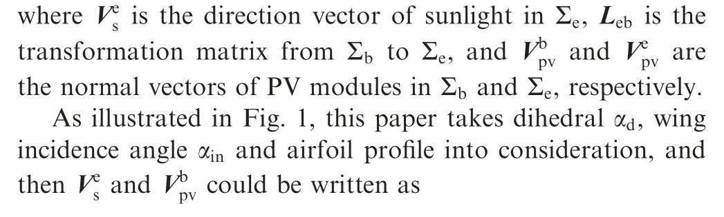
Fig.1 Illumination model of photovoltaic module coupled with wing configuration.
Then the current Ipvcan be obtained by
where Umpptis the set output voltage of MPPT.
Therefore, the EMI generated by PV modules also originates from the current.It is related to trajectory,which affects the solar energy harvest.
2.3.Models coupling
The flight demand power PDcan be given by both Eq.(2)and hybrid power system as
where Uoutis the output voltage of hybrid power system.
In this paper, the projection of EMI of a hybrid powered UAV ΔB on the geomagnetic vector Beis taken as the actual influence at the measured geomagnetic elements, which can be written as
where X,Y,Z are direction angles,formed by Bewith Σbaxes.Bx, By, Bzare EMI components on axes of Σb.
In Σb,axes xb,yb,and zbpoint to left wing,nose and belly,respectively.The cosine values of direction angles could be obtained.A linearized expression is
where Ieis the geomagnetic inclination.Magnetic heading θ~=θ-De, where Deis geomagnetic declination.

Fig.2 Definition of coordinate systems and variables.
A visual explanation is shown in Fig.2.Eqs.(13) and (14)reveal that the EMI varies with geographic location and the results of trajectory planning.
3.EMI mechanism modeling of batteries
The EMI is hard to be precisely described because of the complex redox reaction and photovoltaic effect.Considering that mechanism modeling is widely used,23the concept of‘‘equivalent current”is proposed based on Biot-Savart law to describe the macro EMI quantitatively.
3.1.EMI of lithium battery
As shown in Fig.3, the concept of equivalent current ILiis extended based on Ref.14, where ILiis roughly assumed to be located at half of length l of battery.In fact,due to the uneven redox reactions, the location of lLineeds to be identified.
The modeling is based on the following assumptions:
(1) lLiin each slice of lithium battery(denoted as S1,S2,...,SNLiin Fig.3) is the same;
(2) w(width of ILi)is the same as that of the battery,whose magnitude is equal to the output current;
(3) Lithium battery is located in the longitudinal plane of symmetry with adjustable inclination φLi∊[-π,π].
Considering the series arrangement of battery internal electrodes, the EMI generated by ILican be obtained by
where μ0=4π×10-7V ∙s/(A ∙m) is the vacuum permeability, NLithe total number of battery slices, rithe distance between current element and magnetometer,and Δd the thickness of a single cell.,ybatandare the distance and its horizontal and vertical components between ILiof the i-th battery slice and magnetometer, respectively.θi1and θi2are the azimuth from both ends of ILito magnetometer.

Fig.3 EMI mechanism of lithium battery.
Accordingly, once lLiis identified, Eq.(15) can be determined.The experimental system is established in magnetically stable environment.The equipment used for lLiidentification includes magnetometer, host computer, electronic load and the battery sample.The parameters of the sample are presented in Table 1.
During the test,ILiis gradient loaded by the electronic load in ΔI=1 A with all wires twisted in pairs.EMI of the battery sample ΔBLiis obtained by
where Bm|Iis the measurement of EMI with current I, and‖∙‖2the square norm operation.
Results are shown in Fig.4.Since ΔBLi∝ILi,lLiis obtained by least square method.lLi/l equals 34.6%instead of 50%.The average modeling error is 8.22%.The identification has taken into account external factors such as uneven redox reactions and incomplete twisted wires, and thus it is a macroscopic manifestation of BLi.
When ILi=15 A and φLi=0°,the key parameters are analyzed separately(while other parameters maintain the values in Table 1).As shown in Fig.5, the EMI of lithium battery increases with w and Δd,but decreases with ybatand zbat,which is of guiding significance for special battery design and fuselage design.
3.2.EMI of PEMFC
The mechanism modeling method of PEMFC is similar to that of lithium battery.PEMFC is composed of compression plates, current collector, bipolar plates, Gas Diffusion Layer(GDL) and Membrane Electrode Assembly (MEA).26IFCflows in current collector and bipolar plates, which is where EMI is generated.Consequently, this paper uses 4 equivalentcurrent segments with intensity equal to IFCto describe EMI model of PEMFC.
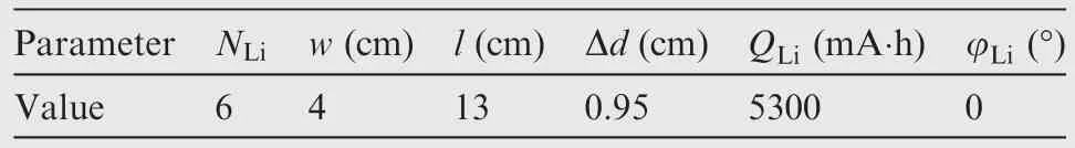
Table 1 Parameters of lithium battery sample.
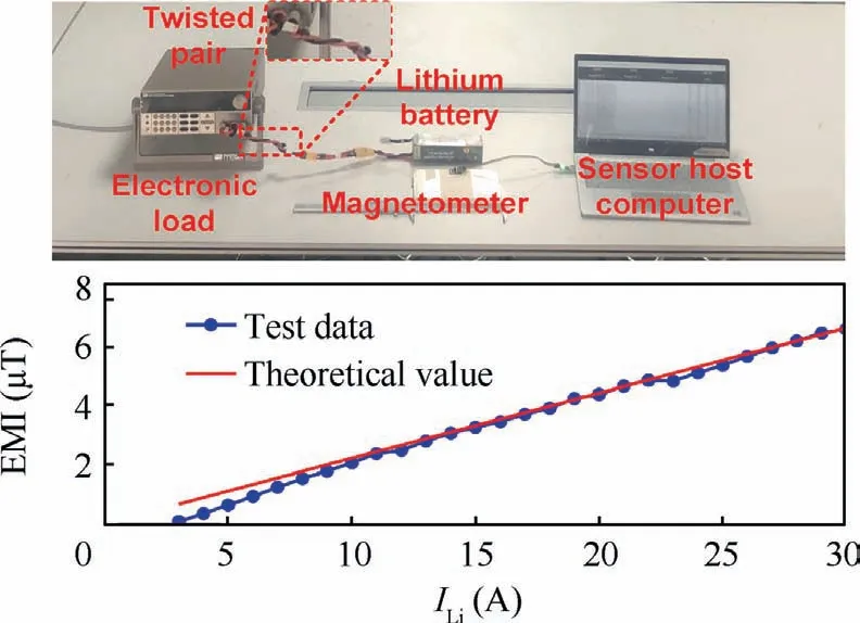
Fig.4 Test equipment and identification of lithium battery sample.
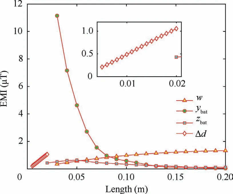
Fig.5 Parameter analysis of EMI of lithium battery.
As shown in Fig.6, for electrified collector plate, since the electrode is at one corner, IFC1,2are equivalent to the parallel current with the position biased towards the electrode.For IFC3flowing among multiple single cells in series, considering the stable temperature distribution and relatively symmetrical current density distribution,26IFC3is equivalent to being located along the central axis of PEMFC stack.In addition,for ease of use, electrodes of PEMFC are pulled to the same side.Therefore, there is an extra IFC4on the surface.
Unlike lithium battery, there are several constraints for placement of PEMFC:
(1) The range of φFC∊[0,π/2]to ensure the exhaust hole is at the bottom;
(2) PEMFC fans shall be arranged on the side to dissipate heat outside the cabin to achieve better heat dissipation.
Therefore, in accordance with Biot-Savart law, the EMI BFCof PEMFC generated by the 4 current segments can be expressed as
where Diis the distance between IFCi(i=1,2,3,4)and magnetometer,and θi1and θi2are the azimuth from both ends of IFCito magnetometer.
Then, similar to lLi, the locations of IFC1,2are needed to be identified to determine Eq.(17).Analogous to Section 3.1,PEMFC EOS1000 (produced by Pearl Hydrogen Technology Co., Ltd27) was selected as test sample.The size, Normal Rated Power (NRP) and Normal Rated Current (NRC) are shown in Table 2.During the test, IFCis gradient loaded in ΔI=1 A with all wires twisted in pairs.
The results are shown in Fig.7.Due to fan EMI, the distance between IFC1and IFC3increases to 0.575 b(>0.5b),while the distance between IFC2and IFC3is 0.25 b, because IFC2has little impact compared with IFC1.After identification,the average modeling error is 7.48%.
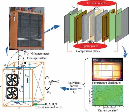
Fig.6 EMI mechanism of air-cooling PEMFC.
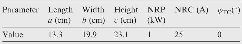
Table 2 Parameters of PEMFC sample.
Similarly, as shown in Fig.8, when IFC= 15 A and φFC= 0°, the EMI of PEMFC decreases with b and c, and is less affected by a.As for distance from rotating axis to magnetometer R, the EMI reaches its peak atR = 0.16 m, and therefore, it needs to be avoided.
3.3.EMI of PV modules
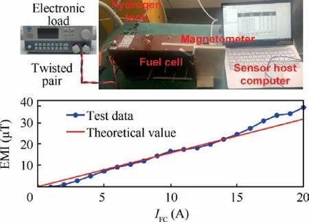
Fig.7 Test equipment and identification of PEMFC sample.

Fig.8 Parameter analysis of EMI of PEMFC.
PV modules generate power by photovoltaic effect.To establish EMI model of PV modules, this paper starts with the mechanism analysis underlying one single piece of solar cell.A single cell is composed of photovoltaic welding strips,pectinate electrodes, anti-reflection layer, N-type and P-type semiconductor.The contact between two semiconductors is the depletion region where photovoltaic effect is active.
As shown in Fig.9, under illumination, the electrons of Ntype semiconductor are excited and overflow out of depletion region.They are collected by a large number of pectinate electrodes on the cell surface, are merged into the photovoltaic welding strips,and then enter the internal bus lines.After passing through the consumer,the electrons return back to welding strips connecting the positive pole on the surface back to light of the cell, fill the cavities of the P-type semiconductor and wait to be excited again.Multiple cells are connected by welding strips and internal bus lines in series to increase the module voltage.
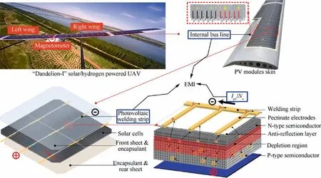
Fig.9 EMI mechanism of PV modules.
For most commercial off-the-shelf PV cells,we consider that:
(1) The thickness is too thin to be ignored.28
(2) Voltage difference among and current in pectinate electrodes are small.
Therefore, equivalent current produced by PV effect along the thickness direction could be ignored.The EMI generated by a single cell can be regarded as that generated by a twodimensional illuminated plane.Proceeding to the next step,due to the same current magnitude and opposite direction,the EMI of symmetrical pectinate electrodes can offset each other to a great extent.Then, for the whole wing, EMI of PV modules Bpvis actually generated by finite length current in double-layer welding strips Iwsand the internal bus lines Ibl.
Based on the mechanism analysis,EMI of a PV module can be expressed as
where r is the distance between current and magnetometer,Nwsand Nblare the number of welding strips and internal bus lines,respectively, and θi,j2and θi,j2are the azimuth between the beginning and end position of current and magnetometer.
Considering the current shunting effect,as shown in Fig.9,Ibland Iwssatisfy
where Nsis the number of welding strips imported into each internal bus line.
The model is verified by similar test with no Maximum Power Point Tracking (MPPT) device included.The sample is a standard plane PV module with height h= 0.61 m, width lpv= 0.56 m and NRP = 30 W.
The date and module inclination of the test is randomly selected.During the test, Ipvis gradient loaded by the electronic load in ΔI=0.2 A with all wires twisted in pairs.As shown in Fig.10, the test results are in good agreement with the mechanism model, with an average modeling error of 7.5%.
The analysis of key parameters of PV module is shown in Fig.11.When Ipv= 1.5 A, the EMI of PV modules increases slightly with the number of welding strips n along h and lpv,and decreases with ls(distance from magnetometer to PV module) and dh (distance between adjacent welding strips).Therefore, PV cells with large size and smaller pectinate electrodes should be used to reduce EMI.
Heretofore, the test results demonstrate that the average modeling errors are acceptable, and the proposed modeling method based on equivalent current is efficacious.Although EMI decays with distance, it is precisely because of the compact distribution of avionics that magnetometer will be greatly affected.However, it should be noted that the location of equivalent current would be affected by the aging, activation level and internal reaction uniformity, as well as incomplete twisted wires.Therefore, the parameters of the EMI models need to be identified before flight.
4.EMI reduction methods and simulation of hybrid power system
4.1.EMI reduction scheme
For EMI reduction problem of hybrid powered UAVs with various configuration and energy topology, an online 3-layer scheme is proposed to systematically and universally reduce the EMI generated by the hybrid power system.

Fig.10 Experimental verification of PV module EMI.
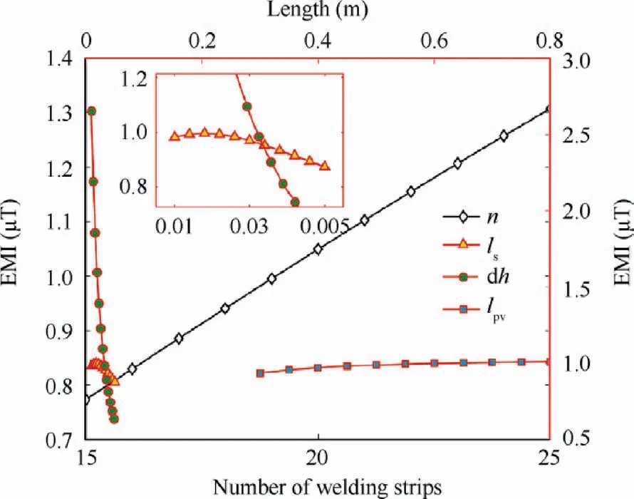
Fig.11 Parameter analysis of EMI of PV modules.
Layer 1.Battery layer, which accommodates the battery posture or makes circuits symmetrical to realize EMI selfcancellation.
However,in engineering practice,the following errors must also be considered to make the scheme universal:
(1) Tracking error of battery posture caused by measurement error of Euler angles and heading, control delay,etc.
(2) For the UAVs that do not allow the battery to rotate in the cabin, the preset sub-optimal inclination cannot eliminate EMI to 0 in real time.
(3) Dihedral and deformation of the wing structure with high aspect ratio will cause the EMI generated by the left and right half-wings not completely along the zbaxis,making it difficult to realize EMI self-cancellation.
(4) Even for completely rigid wings without dihedral, local shadows and hidden damage of PV cell may still exist,which makes EMI of PV modules at magnetometer in opposite directions but with different intensities.
Thus, considering the coupling relationship between EMI and flight state, EMI can be reduced through trajectory.
Layer 2.Trajectory planning layer,which generates an optimal or sub-optimal trajectory to reduce EMI.
In addition, the hybrid UAV must coordinate the energy supply relationship through energy management strategy.Then differences in EMI characteristics can be further considered while meeting the long endurance demand.
Layer 3.Energy management layer, allocating more power to the power source capable of generating small and stable EMI.
4.2.First main layer: Battery layer
4.2.1.EMI self-elimination method of lithium battery and PEMFC
A simple and effective method is proposed to realize EMI selfelimination of lithium battery and PEMFC by changing their inclinations along the cabin.
In accordance with Eq.(15)and Eq.(17),both BLiand BFCare functions proportional to current,which can be collectively expressed as
where k(φ )is the proportionality factor,φ the battery inclination, and Λ the azimuth from battery to magnetometer.
Submit Eq.(20) into Eq.(13), and ΔB can be rewritten as
Therefore, a closed-form EMI-optimal inclination φ*can be found to make ΔB be 0:
φ*is only related to the direction angles(X,Y,Z)and battery azimuth Λ,independent of battery types.However,quantitative analysis is still necessary to the evaluation of EMI in various scenarios.For UAVs that are not capable of adjusting φLior φFC, fixed and sub-optimal angles could be preset according to flight path.
4.2.2.EMI self-elimination ability analysis of PV modules
The PV modules cannot adjust their attitude at will like lithium battery or PEMFC, because they are firmly fixed with the wing.Then, for PV modules, the approach to reduce EMI is circuit layout design.
On the one hand, as shown in Eq.(18), even the conventional circuit layout can achieve limited EMI reduction effect,because its routing is S-shaped, and the currents in different directions in the welding strip produce opposite electromagnetic fields and reduce each other.
On the other hand,as illustrated in Eq.(23),if the PV modules on the left and right half-wings are symmetrical and connected in parallel, the EMI at magnetometer generated by the two half-wings can offset each other to a great extent,because(A) the magnetometer is usually located on the longitudinal symmetry plane of the UAV; (B) airfoil with small upper surface curvature is usually adopted in order to harvest more solar energy;(C)the two half-wings share the same Euler angle of Σbas a whole.In addition to the possible dihedral, the energy and current generated by the two half-wings are similar.
where indexes L and R refer to the left and right half-wings,respectively.
4.3.Second layer: Trajectory optimization for reducing EMI
The trajectory planning problem with pseudo control variables α, β, γcand δ can reduce PDso as to reduce the current of lithium battery and PEMFC, or reduce time consumption for flight tfto stabilize the EMI change of PV modules.Therefore, the cost function J could be expressed as
where t0and tfare the initial and terminal time of the trajectory, respectively.
The hp-adaptive Radau pseudo-spectral method with model-based variables reduction strategy is proposed to solve the complex Non-Linear Programming (NLP) problem with various variables.
Step 1.Convert time interval [t0,tf] to [-1,1]:
Step 2.Global interpolation approximation of state and control variables:
where Lagrange polynomial function Li(τ )can be provided by
Step 3.Transforming differential equations into algebraic constraints with variables reduction strategy:
On τk, the derived Eq.(26) can be discretized as algebraic form:
Some numerical improvements are adopted in this step to reduce the number of variables.According to Eq.(28),Eq.(1)and Eq.(2)can be rewritten in the form of algebraic equations:
Based on the characteristics of the UAV motion model,the above equations can be changed to
Then the number of state variables is reduced from 16 to 10, and the convergence speed can be greatly improved.
Step 4.Discretization of constraints Ciand cost function J:
where ωkis the Gaussian weight.
4.4.Third layer: Energy management for power allocation
The 3rd layer allocates more power preferentially to the power source capable of generating small and stable EMI.
Besides EMI change rate with inclination, the limited hydrogen is the main factor restricting endurance.Hence, PV modules are preferred on the priority of power allocation,followed by lithium battery,and finally PEMFC.The designed 2-echelon power system topology is shown in Fig.12.
The first energy manager actively gives priority to solar energy and lithium battery.Manager of the second echelon starts PEMFC stack when power is insufficient.If PDis still not met, the UAV will adjust the trajectory to achieve power matching.
The flowchart of the corresponding energy management strategy in the form of Finite State Machine (FSM) is shown in Fig.13,where SOCLand SOCHare the minimum and maximum available SOC of lithium battery respectively, SOPLis the minimum available State of Pressure (SOP) of PEMFC,and PFCminand PFCmaxare the minimum and maximum output power of PEMFC respectively.PD1, PD2, and PD3are residual demand power.The proposed management strategy takes into account the endurance and EMI reduction.Besides, its FSM form only includes multiple judgment links, and can passively realize power matching and distribution according to rules.Hence, it has stable and real-time application capability.
5.Numerical simulation
In this section, based on the given UAV model, the effect of the first main layer is verified.Then, the overall simulation and analysis of the 3-layer scheme are carried out in three typical scenarios covering all flight profiles of the hybrid powered UAV: climb, level flight and descent.The simulations are implemented in MATLAB2018b on PC with Intel Core i5-8400 2.80 GHz and 8 GB RAM.
5.1.UAV prototype for simulation
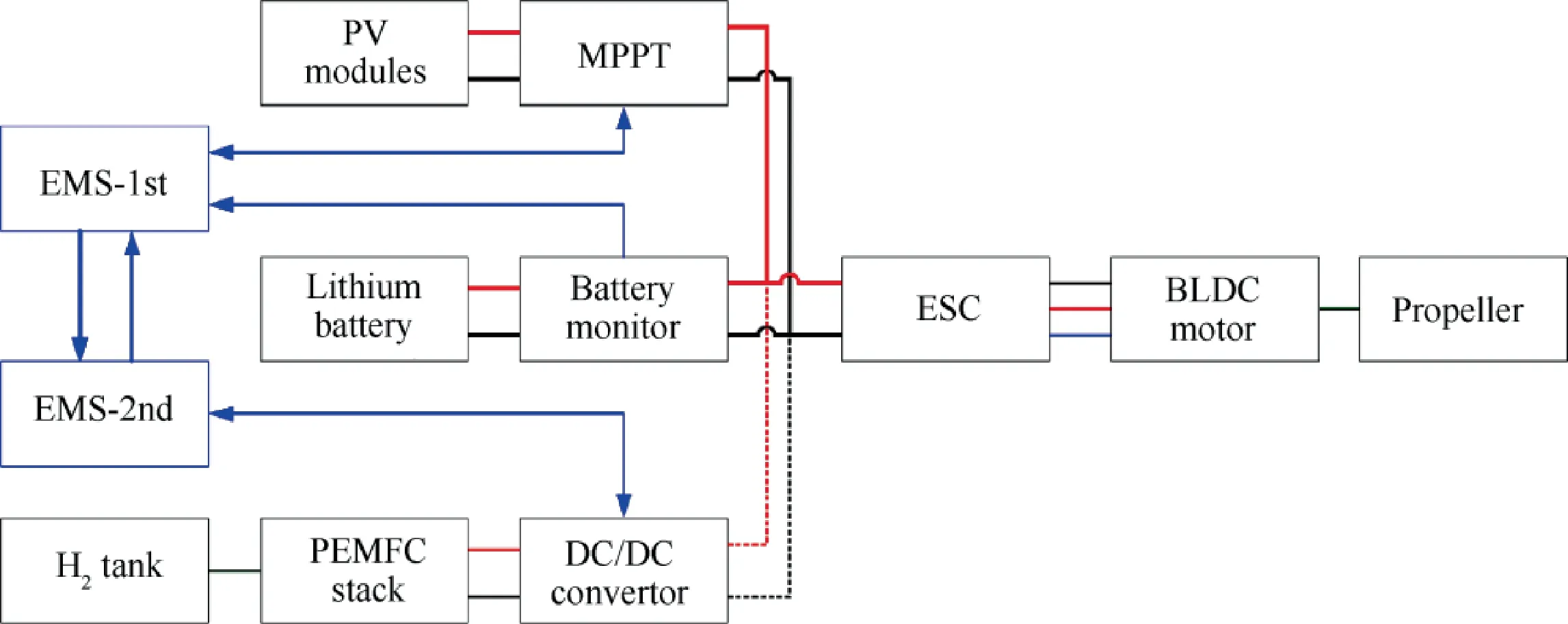
Fig.12 Hybrid power system topology with two-echelon energy management system.
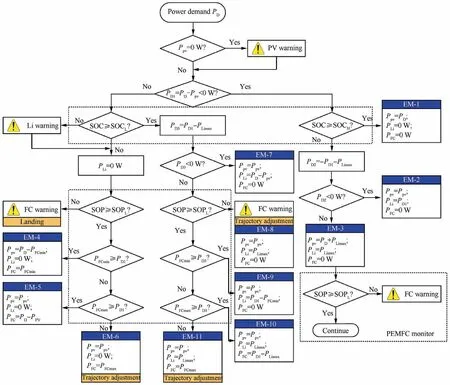
Fig.13 Energy management strategy of hybrid power system topology.
As illustrated in Fig.14, a solar/hydrogen hybrid powered UAV ‘‘Dandelion-I” is taken as an example.The semiflexible PV modules are directly used as wing skin for weight reduction.In order to avoid the thermal impact of aircooling on avionics equipment, the PEMFC stack is placed at the rear of the cabin.Lithium battery and the hydrogen cylinder are placed in the front for longitudinal trim.Integrated with the GPS module, magnetometer is placed above the Center of Gravity (CG) to facilitate positioning and controlling.The parameters are shown in Table 3, where Cl0and Clαare the value of lift coefficient with α=0 rad and lift coefficient derivative to α, respectively, and Cd0is zero lift drag coefficient.
Geomagnetic field in the area is considered to be stable,with Be=50 μT, Ie=π/3 and De=π/36.
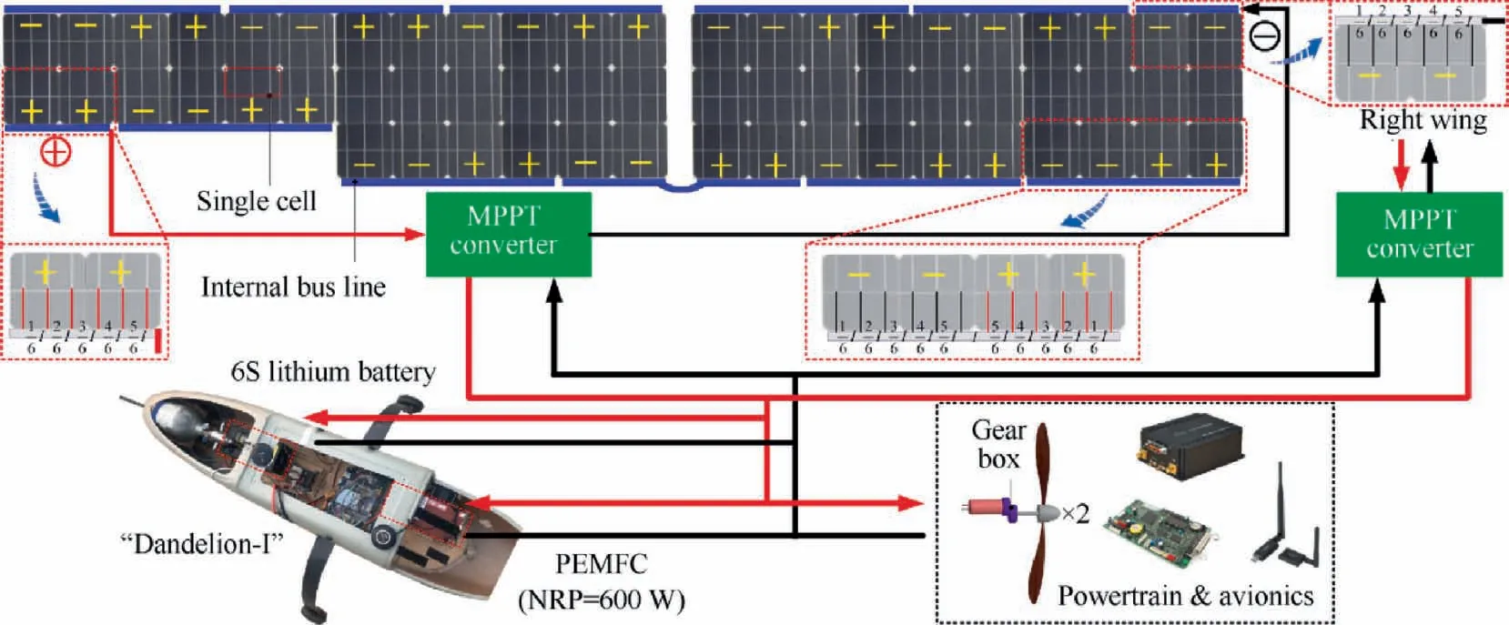
Fig.14 Hybrid power system topology of ‘‘Dandelion-I”.

Table 3 Parameters of ‘‘Dandelion-I”.
5.2.First main layer
5.2.1.Lithium battery and PEMFC
Assume that the UAV flies along the path with θ=π/9, and then the relationship between current coefficient and battery inclinations is shown in Fig.15.
The result indicates that EMI self-cancellation of lithium battery and PEMFC can be realized by simply adjusting one angle.On the other hand,because PEMFC is closer to magnetometer,the EMI of PEMFC has a greater impact and is more sensitive to the change of inclination.Consequently, making lithium battery output more power can avoid EMI mutation even more.
For hybrid powered UAVs with narrow cabins,the inclinations could be optimized but fixed in advance according to the main heading, while for those with spacious cabins, inclinations could be adjusted in real time by actuators.
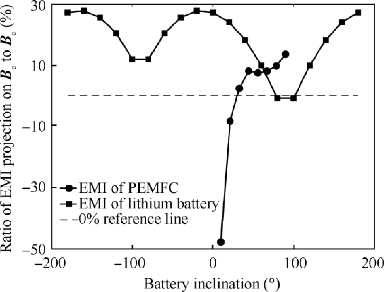
Fig.15 Influence ratio of BFC and BLi on Be.
5.2.2.PV modules
The semi-flexible PV modules are used as skin.The distribution of PV cells is shown in Fig.14.The parameters of wing and PV modules are shown in Table 4.
αiinin Eq.(10)can be estimated by combining layout of PV cells, airfoil profile, αinand αd.Take the middle wing segment as an example, and αiincan be estimated to be 8°, -2° and-10°, as illustrated in Fig.16.
Simulation time is at 14:00 on summer solstice with the highest illumination Ps=1352 W.The EMI change of the single-sided PV module and the two-sided PV modules with Euler angles and heading is shown in Fig.17.
For a single-side half-wing, the impact ofon Beis about 4%, which is the smallest among the power sources.Bpvhardly changes with pitch and yaw because they have little influence on the illumination incident angle, while Bpvis more sensitive to the roll angle.However,the symmetrical circuits of the half-wings on both sides make the overall Bpvlower than 0.1%, which is negligible.When Euler angles are [0°,0°,0°]Trad, for all heading, EMI of the whole wing is lower than 0.1%.Considering the highest illumination, PV modules with symmetrical circuits can be regarded as having the ability of EMI self-elimination.
To sum up, for a small-scale UAV with symmetrical circuits, Bpvcan realize self-cancellation.Theoretically, if the wing of UAV is straight with no dihedral, Bpvcan be always eliminated to 0 nT.Alternatively, the current difference of PV modules of the half-wings will produce EMI.However,most solar UAVs have dihedral to enhance lateral stability,or wing deformation due to the essential high aspect ratio structure at the current state of technology.
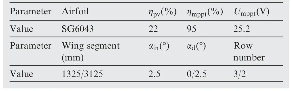
Table 4 Parameters of the analyzed PV modules.
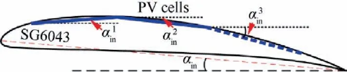
Fig.16 Approximation of incidence αiin of each cell.
For UAVs with smaller wing, it may be difficult to achieve EMI self-cancellation using symmetrical circuits, because it is essential to ensure that sufficient cells are connected in series to generate a satisfactory voltage first.
5.3.Synthetic simulation of 3 layers
In order to ensure a smoother trajectory, ˙α, ˙β, ˙γcand ˙δ are introduced as pseudo control variables.
5.3.1.Scenario 1: Climb
In climb process, the UAV flies from (0,0,100) m to(4500,4500,400) m with V(t0)=V(tf)=15m/s and SOC(t0)=0.45.Denote the trajectory with the minimum arrival time as tf-optimal trajectory, and the most energy-saving trajectory as PD-optimal trajectory.The results are shown in Fig.18.
The results indicate that the UAV climbs rapidly with a max-power of 800 W in tf-optimal trajectory.For the other path, the UAV flies along a more sinuous trajectory with a stable power around 270 W.Thus, less current is produced,as shown in Fig.18(b).The EMI-optimal inclinations of lithium battery and PEMFC could always be found to realize EMI self-elimination, as shown in Fig.18(c).
Accordingly,the power allocation of PDis shown in Fig.18(d).PEMFC will not provide power until SOC reaches its lower bound(0.3)at 251.5 s,and then 10.15 L H2is consumed to help finish the rest path.But in PD-optimal trajectory,SOC slowly increases by 0.02, and 1.2 L H2is normally deflated.Combining with EMI slope in Fig.15, when facing with inclination control errors, lithium battery will generate small and stable EMI firstly.However, SOC will also be consumed rapidly, as shown in Fig.18(e).
The change of EMI is shown in Fig.18(f).When φLi=φFC=0°, reducing power can effectively reduce EMI.It should be noted that, when PEMFC starts power supply,EMI drops precipitously because the direction of BLiand BFCare opposite to each other,resulting in mutual elimination.When φLiand φFCcan be adjusted adaptively (Fig.18(c)), the EMI can be significantly reduced by 99.1% in tf-optimal path and 72.0%in PD-optimal path.Nevertheless,based on layer 1,reducing power cannot generate less EMI.The reason is that Bpvis the EMI residual of the whole aircraft in this case, and the sinuous path will lead to the change of roll angle,resulting in greater
5.3.2.Scenario 2: Level flight
In level flight, the UAV flies from (0,0,400) m to(4500,4500,400) m with V(t0), V(tf) and SOC(t0) the same as those of scenario climb.The results are shown in Fig.19.The PD-optimal path is still more tortuous,its time is about 150 s less and PDis about 1/3 of that of the tf-optimal path.Energy from lithium battery and PV modules is consumed at the same time in tf-optimal path, while in PD-optimal path,PV modules provide energy for level flight and battery charging (PLi<0 W) simultaneously all the way, not only making the BLidirection of the two paths opposite,but also increasing SOC by 0.13,which is beneficial for long endurance level flight,as shown in Figs.19(d) and (e).
As for EMI, the phenomena are consistent with climb, as shown in Fig.19(f).For UAVs that are not capable of changing φLiand φFC, reducing PDcan effectively reduce EMI.For UAVs that can eliminate BLiand BFCadaptively,reducing PDor tfcan both reduce EMI by 99.1% and 97.6% in tf-optimal and PD-optimal paths, respectively, while reducing tfis better for it can avoid generating more

Fig.19 Results of Scenario 2.
5.3.3.Scenario 3: Descent
In the scenario of descent, the UAV flies from (0,0,400) m to(4500,4500,100) m with V(t0), V(tf) and SOC(t0) the same as those of other scenarios.The results are shown in Fig.20.
The phenomena of descent are basically consistent with the other 2 scenarios.The only difference lies in the effect of EMI elimination (see Fig.20(f)), where tf-optimal path is superior over PD-optimal path, whether φLiand φFCcan be adjusted or not.This is because when descending, tf-optimal path only consumes solar power, while for PD-optimal path, in addition to similar consumed solar power, lithium battery is charging,which leads to extra EMI.
In conclusion, to produce less EMI, classified discussion should be conducted.For UAVs are not capable of changing φLiand φFC, energy saving climb and level flight, as well as rapid descent, should be adopted.For UAVs are capable of changing φLiand φFC, EMI of energy saving or time saving trajectories are similar.The latter is better for generating a little bit lower EMI, but not conductive with long endurance.
In the above three scenarios, the time required to generate tf-optimal trajectory and PD-optimal trajectory is shown in Table 5.The CPU time required by tf-optimal trajectory is generally shorter than that required by PD-optimal trajectory because the discretization of PDtakes longer than that of t.However, the time required for all optimization is approximately less than 10 s, meeting the basic online application requirements of a low-speed hybrid powered UAV.

Fig.20 Results of Scenario 3.
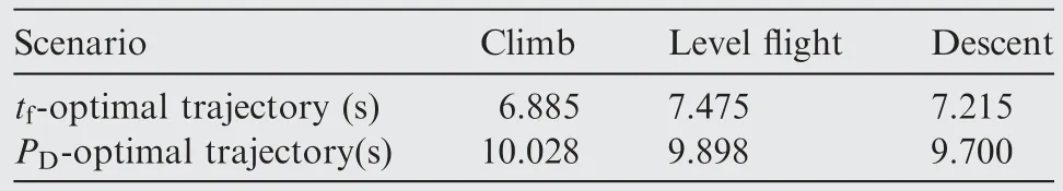
Table 5 Time required for trajectory optimization.
A note of caution is due here.There have been various cost functions for planning.However,no matter what cost function is used, the battery layer plays a major role in elimination of EMI.
6.Conclusions
(1) Some exploratory but systematic work for quantifying and reducing the DC EMI of a solar/hydrogen hybrid powered small-scale UAV has been done in this paper.EMI mechanism modeling and an online 3-layer EMI reduction scheme were proposed to minimize the impact of EMI at the airborne magnetometer from a new direction.
(2) A mechanism modeling method of macroscopic EMI of lithium battery,PEMFC and PV modules was presented based on the proposed concept of ‘‘equivalent current”.The test data showed that the modeling errors are within 10%, which are acceptable, and also proved the effectiveness of the EMI mechanism modeling method.
(3) An online 3-layer EMI reduction scheme was designed,including battery layer, trajectory planning and energy management.Taking a solar/hydrogen hybrid powered UAV as an example, the strategy was simulated.The results showed that the proposed strategy can reduce the EMI intensity by more than 70% online, up to 99.1%.
(4) The full profile simulation including climb, level flight and descent illustrated that the proposed scheme can effectively reduce EMI.Among them, the climb and level flight phase could reduce EMI by minimizing flight power, while the descent phase could minimize flight time to reduce EMI.
(5) The EMI mechanism modeling method and the prototype of EMI reduction scheme are also of significance to both overall design of hybrid powered UAV and battery design.It can be used not only for small-scale hybrid powered UAVs, but also for other electric vehicles.
Declaration of Competing Interest
The authors declare that they have no known competing financial interests or personal relationships that could have appeared to influence the work reported in this paper.
 CHINESE JOURNAL OF AERONAUTICS2023年10期
- CHINESE JOURNAL OF AERONAUTICS的其它文章
- Experimental investigation of typical surface treatment effect on velocity fluctuations in turbulent flow around an airfoil
- Oscillation quenching and physical explanation on freeplay-based aeroelastic airfoil in transonic viscous flow
- Difference analysis in terahertz wave propagation in thermochemical nonequilibrium plasma sheath under different hypersonic vehicle shapes
- Flight control of a flying wing aircraft based on circulation control using synthetic jet actuators
- A parametric design method of nanosatellite close-range formation for on-orbit target inspection
- Bandgap formation and low-frequency structural vibration suppression for stiffened plate-type metastructure with general boundary conditions