
Payload-oriented control scheme for rotating payload satellite considering inertia uncertainties and measurement errors
2023-11-10 02:16YataoZHAOChengWEIChengfeiYUEXibinCAO
CHINESE JOURNAL OF AERONAUTICS 2023年10期
Yatao ZHAO, Cheng WEI, Chengfei YUE, Xibin CAO
School of Astronautics, Harbin Institute of Technology, Harbin 150001, China
KEYWORDS
Abstract For the remote sensing satellite with an unbalanced rotating payload suspended by an Active Magnetic Bearing (AMB), this paper proposes a payload-oriented control scheme where the high-precision payload attitude control is dominating.Firstly, to suppress the disturbances induced by payload inertia uncertainties and state measurement errors, an integrated framework of parameter identification and nonlinear predictive filtering is proposed to estimate payload inertia parameters and system states from multi-timescale, noise- and drift-contaminated measurement data, breaking the mutual constraint between identification and filter.Secondly, based on the estimation results,the control law and bearing electromagnetic force allocation strategy of the payloadoriented scheme are provided, so that the payload tracks the desired motion and the satellite platform follows payload to prevent the air gap of AMB from exceeding the safety threshold.Finally,the simulations are carried out to verify the advantages of the proposed control scheme in enhancing the payload control precision and isolating the platform vibration.
1.Introduction
To solve the contradictory relationship between high resolution and wide field of view in remote sensing satellites,different from the inner field of view stitching1and external field of view stitching2methods in the traditional push-broom mode,a new spin-scan imaging mode3is proposed for the Rotating Payload Satellite (RPS) system, i.e., remote sensing satellite with a rotating payload suspended by a Five-Degree-of-Freedom Active Magnetic Bearing (5-DOF AMB).In the RPS system,the 5-DOF AMB is used to connect the satellite platform and the optical payload due to the characteristics of no friction and controllable stiffness.4,5The payload optical axis is perpendicular to the satellite platform’s axial direction, and a wider strip field of view will be obtained when the payload is rotating.More information about the RPS system can be found in the previous work.6
The mass and inertia of the payload considered in the RPS system are large, and this large inertia payload is unbalanced.When the payload rotates relative to the satellite platform,multiple disturbances related to the payload unbalance will be transferred to the satellite platform through the AMB,affecting the control precision of the RPS system.To meet the attitude precision and stability demands of the payload during the imaging phase, the traditional attitude control scheme (platform-oriented scheme) of the RPS system is to control the satellite platform to maintain the ground orientation, then adjust the air gap through the stiffness model of AMB, and finally control the payload’s axial rotation using the flywheel inside the payload so that the payload achieves the desired motion, i.e., rotates at a uniform speed along its axial direction based on ground orientation.3,7The main drawback of the platform-oriented scheme is that there are more error sources in the payload attitude control.The accumulation of satellite platform attitude controller error and AMB connection error results in poor payload control precision.In particular, when the satellite platform is affected by middle-high frequency vibrations from flywheels or large flexible appendages, there are still residual vibrations transmitted to the payload after AMB isolation,affecting the payload attitude stability.
To overcome the above problems, a new concept inspired by the Disturbance-Free Payload8,9is proposed in this paper,which is denoted as the payload-oriented scheme.Combined with the characteristics of the RPS system, payload attitude control is performed by the AMB and the flywheel inside the payload to track the desired motion,and the satellite platform follows the payload so that satellite platform and payload fly in close proximity formation to prevent the air gap of AMB from exceeding the safety threshold.In this scheme, since the payload control is dominating,the force transmission direction is from the payload to the satellite platform,which is opposite to the platform-oriented scheme,so that the payload motion is not affected by the satellite platform control and the error source in the payload attitude control is reduced.Therefore,the payload-oriented scheme can enhance the payload attitude precision and stability, while getting rid of the influence of platform vibration on the payload attitude, providing a static and stable working environment.
Regarding the attitude control of the RPS system,there are two difficulties to be solved: payload inertia parameter (mass,inertia tensor,centroid deviation)uncertainties and state measurement errors.First,the dynamic unbalance and static unbalance of the payload are randomly valued within the balancing error boundary and the payload inertia parameters may change on orbit, i.e., there are inertia parameter uncertainties in the payload-oriented scheme,which will affect the payload control precision and platform vibration isolation performance.To overcome this problem,plenty of research works have focused on controller design for uncertain systems.Based on the nonsingular terminal sliding mode control,Zhang et al.10estimated disturbances, unmodeled errors and uncertainties through a fixed-time extended state observer to achieve six-degree-offreedom control of vertical take-off and vertical landing reusable launch vehicle.For uncertain underactuated systems,Yang et al.11,12introduced neural network into the presented controller to approximate the unknown dynamics, and achieved asymptotic convergence of both actuated and unactuated variables under various constraints.Although these methods can suppress the effects of inertia parameter uncertainties on the payload-oriented scheme, it is difficult to obtain the accurate payload inertia parameters from the above approximate model.Except for control purpose,obtaining accurate inertia parameters is important for subsequent research, such as payload on-orbit balancing.Therefore, the parameter identification algorithm is introduced into the proposed control scheme to identify the payload inertia parameters.The vast majority of studies on spacecraft inertia parameter identification start by establishing linear regression equations with inertia parameters as unknown variables,and then solve the regression equations by optimization algorithms, such as the least-squares algorithm,13particle swarm optimization algorithm14, differential evolution algorithm,15,16and convolution neural network algorithm17.Among them, the least-squares algorithm is the most typical algorithm18and has been widely used to identify the inertia parameters of various space systems.19,20In general,the regression equations in Refs.13–20 were developed with the Newton-Euler equation or the principle of conservation of momentum, where the latter has the advantage of being less susceptible to measurement errors21and needs to be modified into the momentum increment form because the initial momentum is usually unknown.However,in this paper,the introduction of AMB complicates the RPS system dynamic model,and the inevitable modeling errors in the regression equations will accumulate with time,resulting in poor stability of the identification results.Therefore, this paper establishes the regression equations based on the Newton-Euler equation.
Second, in the RPS system, the attitude quaternion is measured by the star sensor and the angular velocity is measured by the gyroscope.The state measurement errors, consisting of noise and drift, reduce the control precision of payload tracking desired motion and platform following payload.For parameter identification, since the output frequency of the gyroscope is higher than that of the star sensor, the multitimescale characteristic of the state measurement reduces the parameter identification precision by lengthening the identification period.And the regression equations based on the Newton-Euler equation are more sensitive to the measurement errors,especially when the acceleration sensor is not available,the acceleration calculated by velocity measurement difference will have a noise amplification effect, which seriously reduces the parameter identification precision.To reduce the influence of measurement errors on the control and identification results, the state measurements can be pre-processed by filtering algorithms.The star sensor and gyroscope combination attitude determination algorithm is widely used,22,23which compensates for the gyroscope drift by the measured value of the star sensor and outputs accurate quaternion estimation at the measurement frequency of gyroscope, eliminating the effects of multi-timescale characteristic and drift.However,the angular velocity estimation obtained by this method is still contaminated by measurement noise and can be improved by further filtering with the attitude dynamics as the process model.Nevertheless, the traditional nonlinear filtering algorithms, such as Extended Kalman Filter (EKF),24Unscented Kalman Filter(UKF)25and Cubature Kalman Filter(CKF)26require the system model to be pre-defined exactly.If the system model involves inertia uncertainties, modeling errors or non-additive noise,the statistics of process noise and measurement noise do not satisfy zero-mean Gaussian white noise,the performance of traditional filtering algorithm will be deteriorated.27,28Therefore,the traditional filtering algorithm cannot provide accurate angular velocity estimation for parameter identification, resulting in low identification accuracy, and the inaccurate identified parameters cannot correct the inertia uncertainties in the filter process model to improve the filtering accuracy, i.e., the traditional filtering algorithm and the parameter identification algorithm are mutually constrained.Many research attentions have been attracted to focus on the nonlinear filtering problem with model uncertainties.Qian et al.29proposed a recursive robust EKF to deal with the attitude estimation filtering problem in the presence of multiplicative noises and unknown external disturbances caused by vibration or jitter.Based on the Mahalanobis distance theory without involving artificial empiricism, Gao et al.30proposed a fading CKF with augmented mechanism to handle the model uncertainty and non-additive noise in hypersonic vehicle navigation.Further, Gao et al.31proposed a new CKF with both adaptability and robustness by fusing the standard CKF, fading CKF,and robust CKF through the principle of interacting multiple models to handle the errors of process model and observation model in vehicle positioning.Crassidis and Markley32derived nonlinear predictive filtering for nonlinear systems, where the optimal state estimation is determined by minimizing a quadratic cost function consisting of a measurement residual term and a model error term, and the model error may take any form.Although the above robust filtering methods can obtain accurate estimates under model uncertainties,there have been limited studies on introducing these methods into the star sensor and gyroscope combination attitude determination algorithm to filter out angular velocity noise and providing a unified consideration of identification and filtering.
According to the above discussion,there are three research objectives in this paper.First,the control architecture and the complete workflow of the payload-oriented scheme considering inertia uncertainties and measurement errors are established.Second, based on the RPS system dynamic model, to suppress the disturbances induced by payload inertia uncertainties and state measurement errors, an identification-filter integrated framework is introduced into the payloadoriented scheme to estimate accurate and real-time payload inertia parameters and system states from the multitimescale, noise- and drift-contaminated measurement data.Due to the strong robustness and superior filtering performance of nonlinear predictive filtering in the presence of inertia uncertainties,33,34the proposed framework integrates the parameter identification algorithm and the nonlinear predictive filtering algorithm into an interactive iteration form based on the star sensor and gyroscope combination attitude determination algorithm.With the contribution of nonlinear predictive filtering, the identification accuracy of payload inertia parameters is improved, and then the interactive iteration mechanism uses the identified parameters to correct the uncertainties of filter process model to further improve the filtering accuracy,breaking the mutual constraint between identification and filter.Finally, based on the RPS system dynamic model and the estimation results, the control law and bearing electromagnetic force allocation strategy of the payload-oriented scheme are provided, including highprecision payload attitude control, platform position following control, and platform attitude following control.It should be noted that this paper only studies the attitude control in the imaging phase,so the mentioned platform position following control does not include the orbital maneuver.To the best knowledge of the authors, there are few studies on the payload-oriented scheme of the RPS system.The main contributions of this paper can be summarized as follows:
(1) Combined with the RPS system characteristics and dynamic model, a payload-oriented control scheme dominated by high-precision payload attitude control is proposed to enhance the payload control precision and isolate the platform vibration influence in the presence of inertia uncertainties and measurement errors.
(2) By integrating parameter identification and nonlinear predictive filtering into an interactive iteration form,the proposed identification-filter integrated framework can obtain accurate and real-time payload inertia parameters and system states from the multi-timescale,noise-and drift-contaminated measurement data,breaking the mutual constraint between identification and filter.
The rest of this paper is organized as follows.In Section 2,a detailed description of the payload-oriented scheme is given.In Section 3,the dynamic model of the RPS system is established,followed by the identification-filter integrated framework.In Section 4, the control law and allocation strategy of the payload-oriented scheme are provided.Simulation results are given in Section5.The conclusions are drawn in Section 6.
2.Payload-oriented control scheme description
As shown in Fig.1,the RPS system consists of a platform subsystem, a payload subsystem, and a 5-DOF AMB.The platform subsystem consists of a satellite platform, solar panels,and a wheel control system with each flywheel number noted as x, y, z.The payload subsystem consists of a rotating payload and an axial flywheel, with the axial flywheel number noted as t.The 5-DOF AMB consists of left Radial Active Magnetic Bearing (RAMB), right RAMB, and Thrust Active Magnetic Bearing (TAMB).
The spin-scan imaging mode requires the payload to rotate at a uniform speed along its axial direction based on ground orientation, noted as the payload’s desired motion.To reduce the error source of the payload tracking the desired motion,we propose the payload-oriented scheme.Meanwhile, the proposed control scheme can suppress the disturbances induced by the inertia uncertainties and measurement errors.
The following assumptions are made to simplify the analysis.

Fig.1 Structure of RPS system.
Assumption 1.The inertia parameters of the platform subsystem and the payload axial flywheel are known,including mass,inertia tensor, and centroid deviation.
Assumption 2.There is no measurement error in the position information of the payload and satellite platform.
When Assumption 1 and Assumption 2 hold, as shown in Fig.2, there are three control loops in the payload-oriented scheme, payload attitude control loop, platform position following control loop, and platform attitude following control loop.The former is used for the high-precision payload attitude control,and the latter two control the platform to follow the payload motion.According to Fig.2, on the premise of establishing the dynamic model of the RPS system,the overall workflow of this scheme is described below.
Step 1.Taking the platform and payload sensor measurements as input, the proposed identification-filter integrated framework outputs the quaternion estimation results and angular velocity estimation results of the platform and payload, as well as the inertia parameter identification results of the payload.
Step 2.Based on the attitude estimation results of the payload, the platform subsystem expected position and attitude need to be calculated to ensure that the platform follows the payload motion and prevents the air gap of AMB from exceeding the safety threshold.
Step 3.The platform position following control law is designed to make the centroid position of the platform subsystem track the position expectation calculated in Step 2, and this control force is provided by AMB with an electromagnetic force allocation strategy according to the principle of minimal impact on the payload attitude.
Step 4.Based on the proposed identification-filter integrated framework,the high-precision payload attitude control law is designed to track the payload’s desired motion by feedforward compensation of the platform position control force effect, and this control torque is provided by the flywheel inside the payload and AMB with an electromagnetic force allocation strategy according to the principle of no additional force disturbance.
Step 5.Based on the attitude estimation results of the platform,the platform attitude following control law is designed in the presence of AMB reaction so that the platform attitude tracks the attitude expectation calculated in Step 2, and this control torque is provided by the platform flywheel control system.
The payload-oriented scheme is achieved by performing the above steps.Obviously, platform position following control is the basis of payload attitude control because payload attitude control needs to compensate for the platform position control force effect; platform attitude following control needs to be designed last because both platform position and payload attitude are controlled by the electromagnetic force of the AMB,and the AMB reaction needs to be considered in the platform attitude following control.Compared to the platform-oriented scheme, the payload-oriented scheme changes the control sequence and force transmission direction, so the payload attitude control is dominating.After the disturbances induced by inertia uncertainties and measurement errors are suppressed, there is no satellite platform attitude control error or AMB connection error in the payload attitude control error, and the payload attitude is not affected by the satellite platform motion.Therefore, the payload-oriented scheme can enhance the payload attitude precision and stability, while getting rid of the influence of platform vibration.
Remark 1.Compared to the platform-oriented scheme, the payload-oriented scheme has additional design steps, such as high-precision payload attitude control, platform subsystem expected position and attitude calculation, platform position following control, and bearing electromagnetic force allocation.Among them, the payload attitude control needs to compensate for the platform position control force effect, and the electromagnetic force allocation needs to consider the structural parameters of AMB and the corresponding allocation strategy,which are the problems to be solved in the design process of the payload-oriented scheme.

Fig.2 Control architecture of payload-oriented scheme.
Remark 2.Since the dynamic unbalance and static unbalance of the payload are randomly valued within the balancing error boundary and may change on orbit,payload inertia parameter uncertainties will lead to control parameter deviation and disturbance feedforward compensation residual in Step 4, which will affect the payload control precision and transmit the vibration of the platform to the payload.Meanwhile, state measurement errors will reduce the payload control precision by affecting the state feedback, and reduce the control precision of the platform following payload by affecting the state feedback and expectation calculation.Therefore,the proposed identification-filter integrated framework is the key to ensure the effectiveness of the payload-oriented scheme.
Remark 3.The payload-oriented scheme proposed in this paper can only isolate the effect of platform vibration on the payload attitude and cannot isolate its effect on the payload position, since the platform position control force is applied to the payload by AMB.It is possible to provide platform position control force by platform thrusters to achieve zero transmissibility from platform vibration to payload attitude and position, but this requires the thrusters to be in operation all the time during on-orbit operation, which will consume a lot of propellants.In addition,the requirement of remote sensing imaging for attitude isolation is much larger than that of position isolation,so the scheme proposed in this paper is optimal from the perspective of isolation requirement and propellant consumption.
3.Dynamic modeling and identification-filter framework of rotating payload satellite

The symbols used in this section are defined in Table 1.
3.1.Dynamic model of rotating payload satellite
The dynamic model of the RPS system,including the platform subsystem model,the payload subsystem model,and the AMB model, has been given in the previous work.6Based on the results of the previous work,6the equations used in this paper are established.Before modeling, the following assumption is made to simplify the analysis.
Assumption 3.The solar panels of the platform subsystem are considered rigid and their rotations relative to the satellite platform are ignored.
When Assumption 3 holds, the dynamic model of the platform subsystem is given as follows:
And the dynamic model of the payload subsystem is given as follows:
where rj=[rjx,rjy,rjz]Tis the vector projection from the coordinate origin of P to the payload’s centroid in P, which is denoted as the payload static unbalance.
Define that r︶kis the position vector from the coordinate origin of P to the payload subsystem centroid.Assume that the flywheel t centroid coincides with the coordinate origin of P, and then the projection rkof r︶kin P satisfies rk=Mprj/Mpl.Further, since Mpl=Mp+Mwtholds, the inertia tensor of the payload subsystem Jplcan be derived as
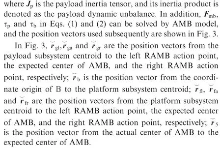
Denote ϑ=[φ,θ,ψ]Tas the Euler angle of the attitude transformation between P and B described by x-y-z order and r5b=[δx,δy,δz]Tas the vector projection ofin B,which can be calculated from the position and attitude information of the satellite platform and payload.According to the AMB model,6one hascenter of AMB to the coordinate origin of P in P; L is the bearing span of AMB and γ=[0,0,1]Tholds.

Table 1 Symbol definition.
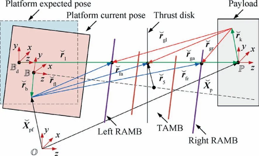
Fig.3 Vector definitions of RPS system.
Then, Fmb, τpand τbcan be expressed as follows:
where Fel,Feaand Ferare the projections of the electromagnetic force vector applied to the payload by left RAMB, TAMB,and right RAMB in B, respectively.
By combining with Eqs.(1)–(5),the refined dynamic model of the RPS system has been established.It should be noted that rP2and L are determined by the geometric parameters of the RPS system and are known quantities, so in Eqs.(1)–(5),only Mp, rjand Jplare unknown, representing inertia parameter uncertainties.
3.2.Identification-filter framework of rotating payload satellite
In this section, to suppress the disturbances induced by payload inertia uncertainties and state measurement errors, as shown in Fig.4, an identification-filter integrated framework is proposed.The proposed framework integrates the parameter identification algorithm and nonlinear predictive filtering algorithm into an interactive iteration form based on the star sensor and gyroscope combination attitude determination algorithm.To simplify the analysis, this paper assumes that the platform angular velocity measurement noise can be ignored.Therefore,like the parameter identification algorithm,the predictive filtering algorithm is designed for payload only.

Fig.4 Architecture of identification-filter integrated framework.
Firstly, due to the slow frequency of star sensor measurements and the drift contamination of gyroscope measurements, the star sensor and gyroscope combination attitude determination algorithm is needed to output accurate quaternion estimation at the gyroscope measurement frequency and filter out the constant drift in angular velocity.At this point,the quaternion estimation and angular velocity estimation are co-frequent, eliminating the effects of multi-timescale characteristic and drift.Secondly, since the angular velocity estimation obtained by the combination attitude determination algorithm is still contaminated by measurement noise,the nonlinear predictive filtering algorithm is used to obtain accurate angular velocity estimation in the presence of inertial uncertainties.Finally,based on the accurate and real-time state estimation results, the parameter identification algorithm is used to identify the payload inertia parameters, and the accurate identified parameters are fed back to the predictive filtering algorithm to correct the uncertainties of filter process model and further improve the filtering accuracy,forming an interactive iteration between filter and identification.In general,compared with the traditional combination attitude determination algorithm, the proposed identification-filter integrated framework filters out the angular velocity measurement noise and breaks the mutual constraint between identification and filter through the nonlinear predictive filtering and interactive iteration mechanism.
3.2.1.Star sensor and gyroscope combination attitude determination
Taking the payload as an example, the gyroscope measurement model is given as
where ˙bp=εpholds,εpis the drift noise and cpis the measurement noise,both of which are zero-mean Gaussian noises with known covariance.
The angular velocity estimation ^ωpsatisfiesand then the estimation error of angular velocity is calculated as

According to the quaternion kinematic equation, one has


where I3is the identity matrix.
Noting that Tcis the period of the combination attitude determination algorithm, one has
where F(k-1) and Γ(k-1) are calculated as follows:
On the other hand, the star sensor measurement model is given as follows:
where qpsis the measurement error,which can be expressed as
where Δθx, Δθyand Δθzare zero-mean Gaussian noises with known covariance.
Noting that the error quaternion of qpmwith respect to^qpis, one has
Due to the small magnitude of the vector component of qps,omitting the second-order small quantities in Eq.(16),one has
where z=qpw,vand H=[I3,03×3] hold.
Using Eq.(12) as the state equation and Eq.(17) as the measurement equation, the quaternion and angular velocity estimation results can be obtained at the gyroscope measurement frequency by the Kalman filter algorithm.Compared to the star sensor measurements, the quaternion estimation results improve the output frequency and filter out the noise effect, and the angular velocity estimation results filter out the drift effect compared to the gyroscope measurements.The specific algorithm workflow is described as follows:
Step 1.Set initial values for quaternion estimation ^qp(0),drift estimation^bp(0),state variable estimation^xp(0),and estimation error covariance matrix Pp(0), respectively.
Step 2.Using ^qp(k-1) and ^ωp(k-1) from the previous moment, predict the quaternion ^qp(k,k-1) at moment k according to Eq.(8) and predict the drift at moment k, which satisfies ^bp(k,k-1)=^bp(k-1).
Step 3.Bring ^ωp(k-1) into Eq.(13) to calculate F(k-1),then predict the state variable ^xp(k,k-1) as follows:
where Wp=cov(wp) holds.Since the combination attitude determination algorithm iterates with the gyroscope measurement period, the measurement result qpm(k) of quaternion at k moment has the following possibility.
Step 4.1.When there is no measurement qpm(k)at moment k,i.e.,the moment k is within the star sensor measurement period,the quaternion estimation^qp(k)and drift estimation^bp(k)at moment k satisfy
Step 4.2.When qpm(k)is measured at moment k,z(k)is calculated according to Eq.(16).Define the covariance matrix of the measurement noise npas Np, and then the quaternion estimation ^qp(k) and drift estimation ^bp(k) at moment k satisfy
Step 5.Calculate ^ωp(k) by ^ωp(k)=ωpm(k)-^bp(k), then return to Step 2 and repeat the above steps.
3.2.2.Nonlinear predictive filtering of payload
The payload attitude dynamic model in Eq.(2) can be expressed as
Defining ^Mp, ^rjand ^Jplas the identified mass of payload,centroid deviation of payload, and inertia tensor of payload subsystem, respectively.Then, Eq.(21) is further derived as
where d denotes the inertia parameter uncertainty disturbance,and one has
where ΔJpl=Jpl-^Jplholds.
Taking ωpas the state variable and Tpas the filtering period, the discrete state equation can be expressed as
Taking ^ωpfrom the combination attitude determination algorithm as the measurement value, the measurement equation is given as
To overcome the mutual constraint between traditional filtering and parameter identification, a predictive filtering algorithm is introduced in this section.Based on the state estimation ω︵p(k-1)obtained by nonlinear predictive filtering at the previous moment, the state estimation ω︵p(k) and the measurement estimation ^ω︵p(k) at moment k are predicted as follows:
where ^d(k-1) denotes the inertia parameter uncertainty disturbance estimation at the previous moment.
Further, the optimization objective consisting of the weighted sum square of the measurement-minus-estimate residuals plus the weighted sum square of the disturbance is given as
where Cp=cov(cp) holds and Q is a positive semidefinite weight matrix.
According to the least square criterion, the following optimal disturbance estimation result can be obtained by minimizing Eq.(27) with respect to ^d(k-1).
Substitute Eq.(28)into Eq.(26)to complete the calculation of the angular velocity estimation ω︵p(k)at moment k.For the corresponding stability and robustness analysis, one can refer to the theorem proposed by Crassidis and Markley32.
3.2.3.Inertia parameter identification of payload
Taking Mpand rjas the variables to be identified,according to Eq.(2),the translation regression equation can be expressed as
Define Ip=[Ix,Iy,Iz,Ixy,Ixz,Iyz]Tas the inertia tensor parameter to be identified,where Ix,Iyand Izare the principal inertia of Jpl; Ixy, Ixzand Iyzare the inertia product of Jpl.According to Eq.(21), the attitude regression equation can be expressed as
where α and β satisfy
Based on the quaternion estimation ^qp(k) from the combination attitude determination algorithm and the angular velocity estimation ω︵p(k)from the predictive filtering algorithm,the real-time least-squares solutions ^Mp(k), ^rj(k) and ^Ip(k) of regression equations can be solved by the recursive leastsquares method.It should be noted that the inertia tensor parameter identification is affected by the unknown payload mass and centroid deviation.Therefore, in the identification of step k,the mass ^Mp(k)and centroid deviation^rj(k)are first identified based on the translation regression equation, and then they are brought into the attitude regression equation to calculate the inertia tensor parameter^Ip(k).
To improve the precision of inertia parameter identification, external excitation can be applied to enrich the motion information of the payload.In this paper, the excitation applied to the payload is provided by AMB, i.e., during the parameter identification process, the electromagnetic forces of the AMB no longer provide payload attitude control law,but instead provide sinusoidal input based on the platform position control law.Meanwhile, the payload keeps rotating at a uniform speed and the platform follows the payload motion to prevent the air gap from exceeding the safety threshold.In general,for the consideration of the RPS system stability, the payload motion at this time is the superposition of small motion on the working state,resulting in the coefficients of rjzand Ixyin the regression equations Eqs.(29) and (30)being small and the condition number of the coefficient matrix being large.Therefore, the inevitable modeling errors of regression equations will lead to a more significant decrease in the identification accuracy of rjzand Ixycompared to other inertia parameters (denoted as main inertia parameters).The specific identification results will be given in Section 5.
4.Payload-oriented scheme control law
Based on the RPS system dynamic model,the state estimation results,and the parameter identification results obtained in the previous section, the control law and bearing electromagnetic force allocation strategy of the payload-oriented scheme are given in this section.
4.1.Expected position and attitude of platform and payload
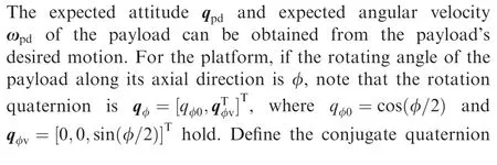

Denote Aφas the attitude matrix of P relative to the platform’s expectation body-fixed coordinate (denoted as Bd, as shown in Fig.3), which can be calculated from qφ, and then the projection ωbdof the platform angular velocity expectation in Bdcan be obtained.
In addition, the platform subsystem centroid position expectation Xpfdcan be given as
where rlis the vector projection in Bdfrom the coordinate origin of Bdto the coordinate origin of P(as shown in Fig.3)and Abdis the attitude matrix of Bdrelative to O.
Further,according to Eq.(33),the platform subsystem centroid velocity expectation ˙Xpfdcan be obtained.
According to Eqs.(31)–(34), the platform subsystem expected position and attitude can be calculated from the position and attitude information of the payload.
4.2.Platform position following control
Let the platform subsystem position error be Xpfe=Xpf-Xpfd,and then the platform subsystem translational equation in Eq.(1) can be expressed as
In this section,the control objective is to design the electromagnetic force Fmbso that the states Xpfand ˙Xpfcan track the desired states Xpfdand ˙Xpfd.Design sliding surface as follows:
where k=diag([k1,k2,k3]T)∊R3×3,and the diagonal elements are all constants greater than zero.
Since V1is positive definite and ˙V1is negative definite,according to the Lyapunov stability theory, the equilibrium point Xpfe=03×1is asymptotically stable, so the states Xpfeand ˙Xpfeon the sliding surface will converge to zero.
Further, to drive the states to the sliding surface, the control law is designed as
where μ>0 and ρ>‖Mpf¨Xpfd‖ hold.
To prove Eq.(38), let the positive Lyapunov function be V2=0.5sTMpfs, and one has
Similarly,according to the Lyapunov stability theorem,the equilibrium point s=03×1is asymptotically stable.Therefore,under the control law Eq.(38), the platform subsystem centroid will track the centroid expectation.Following the principle of minimal impact on the payload attitude, the electromagnetic force allocation strategy of the control law Eq.(38) is given as
where Fer1is the projection of electromagnetic force vector applied by the RAMB for platform position control in B,v=diag([1,1,0]T) and λ=diag([0,0,1]T).
4.3.High-precision payload attitude control
Define that A(qpe)is the attitude error matrix,and then the error angular velocity ωpesatisfies ωpe=ωp-ωpr=ωp-A(qpe)Tωpd.By simplifying the flywheel driving equation and assuming that the flywheel t is installed in the forward direction, Eq.(21) can be expressed as the error dynamics:
When the main inertia parameter identification accuracy and state estimation accuracy are high enough, the following equation can be approximately obtained by bringing the controller Eq.(43) into Eq.(42):

where =[1,0,0]T,χ=[0,1,0]T, and γ=[0,0,1]Thold.
In summary, according to Eq.(40) and Eq.(45), the platform position control and the payload attitude control of the payload-oriented scheme are achieved by applying Felto the left RAMB,Feato the TAMB,and Fer=Fer1+Fer2to the right RAMB.
4.4.Platform attitude following control

Define that A(qbe)is the attitude error matrix,and then the error angular velocity ωbesatisfies ωbe=ωb-ωbr=ωb-A(qbe)Tωbd.By simplifying the driving equations of the flywheel i, and assuming that the flywheels are all installed in the forward direction, the platform subsystem attitude equation in Eq.(1) can be expressed as
where uw=[τwx,τwy,τwz]Tis the driving torque of the wheel control system.
In this section,the control objective is to design the driving torque uw, so that the states qband ωbcan track the desired states qbdand ωbd.Similar to the previous section,the PD control law is proposed based on the feedforward compensation technique.
where Kb=kbJpfand Db=dbJpfhold, kb∊R and db∊R can be adjusted according to the damping ratio and settling time required by the control system.
5.Simulation results
In this section, the ability of the proposed payload-oriented control scheme to suppress the disturbances induced by inertia uncertainties and measurement errors and its advantages over the platform-oriented scheme will be demonstrated by simulation.The RPS system parameters are shown in Table 2.
The remaining parameters of the RPS system are JWi=0.052 kg ∙m2(i=x,y,z), Mwt=28 kg, JWt=1.8 kg ∙m2, rj=[5,0,-9.6]Tmm, Ixz=3.9 kg ∙m2, L=0.146 m, rl=[0,0,2.5508]Tm, rb=[7.9,7.9,7.9]Tmm and rP2=[0,0,0.8016]Tm.Further, the measurement model parameters of the star sensor and gyroscope are shown in Table 3.
To simulate the payload imaging phase,initial values of the quaternion of the platform subsystem and the payload subsystem are both[1,0,0,0]T,and initial values of the angular velocity of the platform subsystem and the payload subsystem are[0.001,0,0]Trad/s and [0.001,0,0.28]Trad/s, respectively.The desired motion of the payload is set to rotate at 0.28rad/s along the axial direction based on tracking orbital angular velocity 0.0011rad/s.
5.1.Induced disturbance suppression
The suppression effect of the proposed payload-oriented scheme on the induced disturbances is verified by simulation.First,the effectiveness of the star sensor and gyroscope combination attitude determination algorithm and the effect of measurement noise on the identification results are studied, which is denoted as Simulation 1.At this time, all the controller parameters of the payload-oriented scheme are k=diag([1,1,1]T), μ=1000, ρ=5, and kp=dp=kb=db=2.The inertia parameters used in the payload attitude control are nominal values, i.e., Jpln=diag([900,900,900]T)kg ∙m2, rjn=[2,0,0]Tmm, and Mpn=750 kg, which are also the initial values of the inertia parameter identification.Meanwhile, the parameters of the attitude determination algorithm are given as follows:

Table 2 Parameters of RPS system.

Table 3 Measurement model parameters.
The period of platform attitude control is 0.1 s.The period of platform position control, payload attitude control, combination attitude determination algorithm, and parameter identification algorithm are all 0.01 s.The simulation duration is 50 s, and after the results of combination attitude determination algorithm are stable, Feland Fer2are changed at 20 s to provide radial periodic torque input with the amplitude of 1.5 N ∙m for identification.
The state estimation results obtained by the combination attitude determination algorithm are shown in Fig.5.As shown in Fig.5(a) and Fig.5(d), the combination attitude determination algorithm outputs quaternion estimation with the gyroscope measurement period and has a high estimationprecision.As shown in Table 4,the maximum standard deviation of the platform quaternion estimation error is 1.63×10⁻⁶for, and the maximum standard deviation of the payload is 2.23×10⁻⁶forwhich are reduced by 74.73% and 72.3% respectively compared with the measurement noise standard deviations mentioned in Table 3.In addition, as shown in Fig.5(b) and Fig.5(e), the angular velocity drift estimation errors of the platform and payload converge to being within 0.1(°)/h, i.e.,the combination attitude determination algorithm filters out 96.67% and 90% of the angular velocity drift of the platform and payload, respectively.Further, from Fig.5(c), Fig.5(f),and Table 4,it can be seen that the angular velocity estimation error standard deviations of platform and payload are similar to the measurement noises mentioned in Table 3, which will seriously affect the subsequent identification precision.

Table 4 Statistical properties of state estimation error.

Fig.5 State estimation results by combination attitude determination algorithm.

Fig.7 Payload angular velocity estimation error.
The results of payload inertia parameter identification are shown in Fig.6, where Fig.6(a) and Fig.6(b) depict the percentage errors; Fig.6(c) and Fig.6(d) depict the absolute errors since the true values of rjy, Ixyand Iyzare zero.It can be seen that the principal inertia, the inertia product except Iyz, and the axial component of centroid deviation are identified with low precision affected by measurement noise, which cannot meet the payload attitude control requirements.
To overcome this problem, the predictive filtering algorithm is introduced to estimate the payload angular velocity,denoted as Simulation 2.The filtering period is set to 0.01 s and the weight matrix is set to Q=diag([50,50,50]T).In addition, the simulation duration is changed to 100 s and the predictive filtering algorithm starts after 15 s.The parameter identification starts after 23 s and forms an interactive iteration with the predictive filtering algorithm.As shown in Fig.7,compared with the combination attitude determination algorithm,the angular velocity estimation of the predictive filtering algorithm not only reduces the standard deviation by 56.49%(from 5.01×10⁻⁶rad/s to 2.18×10⁻⁶rad/s), but also has smoother time-domain characteristics, both of which are conducive to improving the precision of regression Eq.(29) and Eq.(30).

Table 5 Identification precision comparison of two simulations.
On this basis, the payload inertia parameter identification results are shown in Fig.8.For further illustration, the comparison of the identification precision of Simulation 1 and Simulation 2 is summarized in Table 5.According to the results,it can be seen that the angular velocity estimation output by the predictive filtering algorithm significantly improves the convergence speed and stability precision of the inertia parameter identification.However, the modeling errors in the regression equation and the residual noise in angular velocity estimation reduce the identification precision of all inertia parameters, so there are still persistent errors in Fig.8, and the identification precision of rjzand Ixyis significantly worse than that of the main inertia parameters.Although the identification precision of rjzis poor, and the identification precision of Ixyis worse than that of Simulation 1, as mentioned in Section 3, these inertia parameters have small coefficients in the regression equation and contribute little to the model, i.e., even if the identification accuracy of rjzand Ixyis poor,it does not significantly affect the results of the filtering and control.Meanwhile, the main inertia parameters already have high identification precision, converging to being within 2.35%.Therefore, high-precision attitude control of the payload and isolation of platform vibration can be achieved.
5.2.Advantage comparison

Fig.9 Attitude results of platform-oriented scheme.
Based on the payload inertia parameter identification results and attitude estimation results of Simulation 2, the contrast simulation of the payload-oriented scheme and platformoriented scheme is carried out,which is denoted as Simulation 3.The controller parameters,combination attitude determination algorithm parameters, and prediction filtering algorithm parameters of the payload-oriented scheme are consistent with the previous paper.On the basis of inheriting these parameters and considering the vibration isolation and connection accuracy,the platform-oriented scheme sets the control parameters of RAMB as kr=2100.3 and dr=10, and TAMB as kt=8759.8 and dt=6759.8.According to the stiffness and damping model in the previous work,6one has
where kx,kyand kzare the equivalent translational stiffness of AMB in the three-axis direction of B, cx, cyand czare the equivalent translational damping, kaxand kayare the equivalent angular stiffness of AMB in the x-axis and y-axis of B,and caxand cayare the equivalent angular damping.The simulation duration is set to 60 s.Fig.9 and Fig.10 show the attitude results of the platform-oriented scheme and the payloadoriented scheme, respectively.
As shown in Fig.9(a)-(c), in the platform-oriented scheme,there are more error sources in the payload attitude control.The accumulation of satellite platform attitude controller error and AMB connection error leads to poor payload control precision, while in the payload-oriented scheme, due to the reduction of error sources, the payload attitude accuracy is improved from 0.0024 to within 0.001, as shown in Fig.10(a).In addition,Fig.10(b)shows that the payload attitude stability is within 0.0003 (°)/s.Fig.10(c)-(e) show that the air gaps are stable within the safety threshold of 0.0005 m,indicating that the platform position control and attitude control are effective, and the payload and platform fly in close proximity formation.Fig.10(f) shows that the payload attitude control torque uplis stable within 0.48 Nm.Fig.10(g)-(i) show the magnetic pole pair electromagnetic forces for the payloadoriented scheme, where the left RAMB electromagnetic force amplitude is stable at 1.6 N, the right RAMB electromagnetic force amplitude is stable at 1.8 N, and the TAMB is stable within 0.003 N.Obviously, if the identification precision of the main inertia parameters in Section 5.1 can be further improved, further improvement in payload attitude precision will also be achieved.Therefore, in order to improve the identification precision,it is necessary to further improve the filtering precision by more advanced filtering algorithms (which is also beneficial to the payload attitude) and improve the modeling precision of the regression equation, which will be the focus of our future work.
Further, setting the flywheel z of the platform to have a 0.02 mm centroid deviation, which will result in 23 Hz platform vibration during on-orbit operation.At this time, the payload attitude stability results of the platform-oriented scheme and the payload-oriented scheme are shown in Fig.11 and Fig.12.According to the results,it can be seen that in the platform-oriented scheme,there is still residual vibration transfer to the payload after the AMB isolation, resulting in the deterioration of the payload attitude stability to 0.0008(°)/s.On the contrary, in the payload-oriented scheme, due to the high identification accuracy of the payload inertia parameters obtained from Simulation 2, the influence of the platform vibration on the payload attitude is compensated,so the payload attitude stability results are similar to Fig.10(b), which is within 0.0003 (°)/s.The above simulation results show that, based on the proposed identification-filter integrated framework, the payload-oriented scheme designed in this paper can improve the payload attitude control precision and isolate the influence of platform vibration in the presence of inertia uncertainties and measurement errors.

Fig.10 Attitude results of payload-oriented scheme.
6.Conclusions
In this paper, the payload-oriented scheme considering inertia uncertainties and measurement errors has been studied for the RPS system with an unbalanced rotating payload suspended by a 5-DOF AMB.
(1) The proposed identification-filter integrated framework outputs quaternion estimation results with gyroscope measurement frequency, reduces the quaternion measurement noise of platform and payload by 74.73%and 72.3% respectively, filters out the angular velocity drifts by more than 90%, reduces the payload angular velocity measurement noise by 56.49%, and has smoother time-domain characteristics, so that the payload main inertia parameter identification precision converges to being within 2.35%.

Fig.11 Time-domain comparison of payload attitude stability under platform vibration.
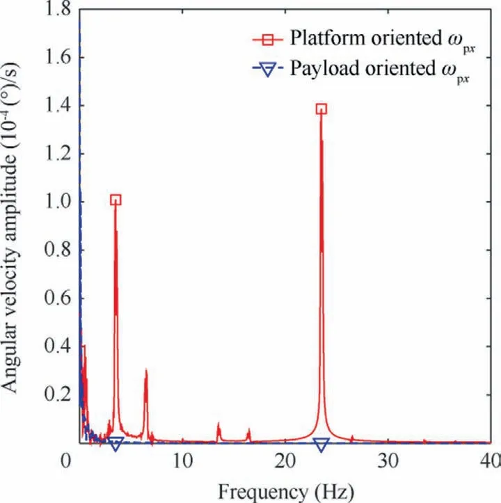
Fig.12 Frequency-domain comparison of payload attitude stability under platform vibration.
(2) Compared with the platform-oriented scheme, the payload attitude accuracy is improved from 0.0024 to 0.001 due to fewer error sources in the payloadoriented scheme.In addition, platform vibration isolation is achieved to get rid of the platform flywheel eccentric vibration influence on the payload attitude stability.
Therefore, the proposed payload-oriented scheme provides an excellent suppression effect on the disturbances induced by inertia uncertainties and measurement errors, and has the advantages of enhancing the payload control precision and isolating the platform vibration, providing a static and stable working environment for the imaging phase of the RPS system.
Declaration of Competing Interest
The authors declare that they have no known competing financial interests or personal relationships that could have appeared to influence the work reported in this paper.
Acknowledgements
This study was supported by the Open Fund of Heilongjiang Postdoctoral Fund, China (No.LBH-Z21141).
 CHINESE JOURNAL OF AERONAUTICS2023年10期
- CHINESE JOURNAL OF AERONAUTICS的其它文章
- Experimental investigation of typical surface treatment effect on velocity fluctuations in turbulent flow around an airfoil
- Oscillation quenching and physical explanation on freeplay-based aeroelastic airfoil in transonic viscous flow
- Difference analysis in terahertz wave propagation in thermochemical nonequilibrium plasma sheath under different hypersonic vehicle shapes
- Flight control of a flying wing aircraft based on circulation control using synthetic jet actuators
- A parametric design method of nanosatellite close-range formation for on-orbit target inspection
- Bandgap formation and low-frequency structural vibration suppression for stiffened plate-type metastructure with general boundary conditions