
Chatter stability of robotic rotary ultrasonic countersinking
2023-11-10 02:16ZhenwenSUNWenheLIAOKnZHENGSongDONGPeiLEILinjunSUN
CHINESE JOURNAL OF AERONAUTICS 2023年10期
Zhenwen SUN, Wenhe LIAO,*, Kn ZHENG, Song DONG, Pei LEI,Linjun SUN
a School of Mechanical Engineering, Nanjing University of Science and Technology, Nanjing 210094, China
b Chengdu Aircraft Industrial (Group) Co., Ltd., Chengdu 610091, China
KEYWORDS
Abstract In recent years,industrial robots have received extensive attention in manufacturing field due to their high flexibility and great workspace.However, the weak stiffness of industrial robots makes it extremely easy to arouse chatter,which affects machining quality inevitably and generates noise pollution in severe cases.Compared with drilling, the chatter mechanism of robotic countersinking is more complex.The external excitation changes with cutting width and depth in countersinking.This characteristic results in time-varying and nonlinearity of robotic countersinking dynamics.Thus,it is urgent to propose a new method of chatter suppression and provide an accurate stability analysis model.As a new special machining technology, rotary ultrasonic machining has been proved to improve robotic drilling and milling stability effectively.Based on this, robotic rotary ultrasonic countersinking(RRUC)is proposed to improve the robotic countersinking stability in this paper.A three-dimensional stability domain method of RRUC is established.First, the countersinking process was divided into ρ parts.The dynamic model of every unit was constructed based on ultrasonic function angle(γ)and dynamic chip area.Then,the stability region of RRUC is obtained based on the semi-discrete method(SDM).Compared with the robotic conventional countersinking (RCC), RRUC improves the stability by 27%.Finally, the correctness and effectiveness of the stability region model are proved by robotic ultrasonic countersinking experiments.
1.Introduction
In modern aerospace industry,riveting plays an important role to connect skin and structure parts of the aircraft.1–3Materials used in modern aerospace industry include composite materials, titanium alloys and aluminum alloys, which are difficult to be machined.4–6According to statistics,the number of rivets on C919 passenger aircraft is more than one million.Drilling and countersinking are the basis of riveting.7–10For such a huge number of drilling and countersinking,it is urgent to find a higher-precision more efficient and economic machining method.In recent years, industrial robots have been widely used in manufacturing field due to their high flexibility, great machining accuracy and economic performance.11–14However, the weak stiffness of industrial robots has become an important factor restricting the further development.15–17During countersinking,the axial force is positively correlated with the cutting width and depth.18The time-varying makes the chatter of industrial robots easier to occur.Serious chatter will not only affect countersinking depth, but also cause irreversible damage to industrial robots and tools.19–22Therefore,the chatter suppression of industrial robots has become a hot topic.23–26
Nowadays, several methods are proposed to suppress the chatter of industrial robots.The stability lobe diagram is used to predict robotic stability.27–29The zero order approximation(ZOA), the semi-discretization method (SDM) and the fulldiscretization method(FDM)are usually used to obtain stability lobe diagram.30–33Roukema and Altintas34presented the dynamic chip thickness of drilling.The ZOA was used to establish the drilling stability model.Cen et al.35proposed that the angle between the main stiffness direction of the robot and the milling force vector direction can be controlled by using the conservative congruence transformation (CCT) stiffness model.It has been proved to avoid the vibration mode coupling chatter of the robotic milling.Meanwhile,Cordes et al.36established the dynamic cutting layer thickness and dynamic milling force model of robot milling.The stability lobe diagram of robot milling is obtained by the ZOA and SDM.Xin et al.37analyzed the tool-workpiece separation model,time-varying process damping model and axial cutting depth modulation model of robotic milling.The time delay coefficient was introduced to explain the improvement of stability region when there was a low-frequency vibration.Shi et al.38analyzed the machining stability of the 5-DOF parallel robot for helical milling.It is found that the spindle speed and the machining pose of the parallel robot play an important role in the stability.Ozturk et al.39put forward a model to predict the cutting thickness of helical milling.According to system dynamic model, the time delay between the spindle speed and the tool path is obtained.And the helical milling stability is solved in discrete-time and frequency domains.It has been proved that strengthening the structural rigidity of the robot and installing various dampers can reduce the vibration during robot machining effectively.40Guo et al.41presented that robotic boring chatter was a forced vibration with displacement feedback.Drigalski et al.42showed an end effector with vibration damping angle.It was used to suppress chatter vibration in robotic drilling.The vibration damping angle can improve the stability of industrial robot efficiently by increasing the frictional force.Chen and Zhao43designed a new eddy current damper which is connected to the spindle.The eddy current damper suppressed the chatter of industrial robots by changing the dynamic characteristics of tool tips.The results indicated that the peak value of the frequency response function at the tool tip decreases by 22.1%and 12.4%in the Z direction, respectively.Yuan et al.44carried out a semi-active MREs shock absorber with adjustable stiffness.The device was fixed on the robot spindle to absorb the vibration energy of mode coupling flutter during machining.In recent years,ultrasonic machining is used to remove difficult-to-machine materials.45–49It has been proved to expand the stability lobe diagram efficiently as a new processing method.50,51Sun et al.52,53established the stability model of rotary ultrasonic machining (RUM).It avoided the robotic milling chatter successfully.The results showed that the stability lobe diagram of milling has increased by 133%when ultrasonic amplitude was 10 μm.At the same time, longitudinal-torsional ultrasonic milling was also proposed.With the intake of torsional ultrasonic, there was a separation between tool and workpiece,which expanded the stability lobe diagram by 124.42%.Dong et al.54proposed the robotic ultrasonic drilling (RUD) firstly.And the stability model of RUD was established.The drilling stability region was extended successfully.In this paper, ultrasonic vibration is used in industrial robots to suppress the chatter.
However, the above research shows that the existing study on robotic chatter stability is mainly focused on drilling and milling.There are few reports on countersinking stability.With the increase of feeding time,the width and depth of countersinking also increase.During countersinking, the force is positively correlated with both the width and depth.Since the excitation of countersinking is dynamic instead of constant, the current research method of stability analysis is not suitable for the robotic countersinking.Therefore, it is urgent to propose a new method for RRUC stability analysis.In Section 2,the dynamic force model of differential unit in countersinking is presented.In Section 3, the mathematical model of SDM is detailed.In Section 4, the experiments are carried out to verify the correctness of the stability lobe diagrams.In Section 5, the reasons for stability region extension of RRUC and effect of ultrasonic parameters on RRUC stability are discussed.
2.Dynamic model of robotic rotary ultrasonic countersinking
2.1.Structural dynamics
In RRUC, the force on each flute is composed of tangential force Ft, radial force Frand axial force Fa, as shown in Fig.1.Since ultrasonic vibration is along the axial direction and tangential direction of flute, a three-degree-of-freedom(3-DOF) equivalent model is established to solve RRUC stability region diagram.The dynamic countersinking system can be formulated as follows:
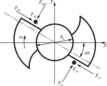
Fig.1 Elemental forces analysis of a two-fluted countersinking bit.
where F is the dynamic force and the vector U represents the deflection of the countersinking in the Cartesian coordinates.Meanwhile, F and U can be expressed as
The matrices M,C and K contain the lumped mass,damping and stiffness characteristics of the RRUC system, respectively.The parameter bdrepresents the diameter of drill.
2.2.Motion analysis of RRUC
Compared with robotic conventional countersinking (RCC),RRUC has different trajectories which lead to a tendency of separation between tool and workpiece.Moreover, the tool kinematic characteristics are changed.The motion of countersinking bit consists of axial feed,circumferential rotation,axial ultrasonic vibration and torsional ultrasonic vibration.The RRUC system and the motion trajectory of cutting edge are shown in Fig.2.The kinematics equations can be written as
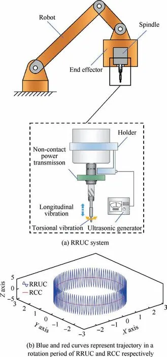
Fig.2 RRUC system and motion trajectory.
where R is the horizontal distance of countersinking bit from the central axis(mm);the parameter ω and t represent angular velocity (rad/s) and time (s), respectively; FUdenotes the frequency of ultrasonic vibration (Hz); AU-Land AU-Trepresent amplitudes of longitudinal vibration(μm)and torsional vibration (μm), respectively; vfis the feed rate (mm/s).
With the intake of ultrasonic energy, longitudinal and torsional velocity are introduced on the cutter.According to Eq.(3), the longitudinal vibration velocity (vU-L) and torsional vibration velocity (vU-T) are written as
As shown in Fig.3, orthogonal coordinate system OXYZ represents the tool coordinate with origin(point O)at the center of the maximum cutting radius.Z-axis is defined as the feed direction.To analyze the effect of RRUC chatter suppression better,the orthogonal coordinate system OUXUYUZUis established.OUis a point on the cutter where the cutting radius is bξ.XU-axis represents the rotating direction.And the connection of vector OUO is set as YU-axis.ZU-axis is the same as Zaxis in the orthogonal coordinate system OXYZ.
In RCC, cutting speed is the compound movement of rotary speed (vr) and feed speed (vf).As the feeding speed is far less than rotary speed, the cutting direction is following the XU-axis.However,the intake of ultrasonic energy changes the cutting direction by introducing axial vibration velocity(vU-L) and torsional vibration velocity (vU-T).Axial vibration velocity(vU-L)and torsional vibration velocity(vU-T)are along the ZU-axial direction and rotating direction,respectively.The cutting direction (vC) changes in the shaded area periodically.To describe periodic change of cutting direction better, the ultrasonic function angle (γ) is defined.γ represents the angle between negative direction of Z-axis and the cutting direction(vC).η is the ratio of torsional vibration amplitude to longitudinal vibration amplitude.The value of γ can be expressed as follows:

Fig.3 Intake of ultrasonic function angle.
As shown in Eq.(5),when vU-L>|vf|,γ is an obtuse angle;when vU-L<| vf|, γ is a sharp angle.
2.3.Dynamic chip area in countersinking
Different from drilling, the chip area which is composed of chip width and thickness changes with time.The countersinking is divided into ρ parts to simplify the model.For the ξ(1 < ξ < ρ) part, as shown in Fig.4, the chip width bξ(mm)is represented by feeding speed and countersinking time.Meanwhile, it can be turned into the relationship of countersinking depth.According to kinematic relationship, the parameter bξcan be expressed as follows:
where dt is the processing time under every infinitesimal(s);the parameter H and f represent the final depth of countersinking(mm)and the axial feeding speed(mm/s),respectively;κtis the half tip angle of the countersinking bit.
As for the chip thickness of ξ part, it can be divided into static chip and dynamic thickness.For the static thickness, it is the result of feed per revolution and the axial ultrasonic vibration.The feed per revolution and the axial ultrasonic vibration in this work can be expressed as
The dynamic thickness is caused by the regenerative chatter in three directions.The regenerative displacements of the orthogonal coordinate system OXYZ are du,which is the combination of dx,dy and dz.Based on the work of Altintas,34the dynamic thickness on each lip is:

Fig.4 Analysis of chip area for ξ part.
2.4.Dynamic countersinking force
The linear function is assumed to describe the force on each flute.There is a linear relationship between the tangential force and actual width of chip and dynamic chip thickness.Meanwhile,the radial and axial force are proportional to the tangential force.The countersinking force on each lip can be expressed as
As illustrated in Fig.3, the directions of tangential and axial force are fluctuated with the period change of ultrasonic vibration.The forces projection on three axis of the orthogonal coordinate system OUXUYUZUcan be expressed as
The cutting force in the orthogonal coordinate system OXYZ is given by the geometric transformation:
Since the static chip thickness hshas no contribution to stability, it could be neglected.The dynamic force in orthogonal coordinate system OXYZ is given by the dynamic thickness.Substituting Eq.(9) and Eq.(10) into Eq.(11), we rewrite the result in matrix form as
All the elements of α(t) and β(t) read as
3.Stability analysis by SDM
At present, SDM was proposed as a time-domain method.It plays an important role to obtain stability lobe diagrams efficiently.According to the work of Insperger,31the ndimensional delay differential equation can be written as
where τ is the time delay and T is the time period.In SDM,the length of Δt represents the construction of the time interval division [ti, ti+1], which means T = kΔt.And k is an integer that can be considered as an approximation parameter regarding the time period.
In this paper,the third-order SDM is obtained based on the second-order system.In the time interval division [ti, ti+1], it can be expressed as
where x(t-τ)i,y(t-τ)iand z(t-τ)iare the items of time delay;J,E and S are written by three matrixes:
where ξnx, ξnyand ξnzare the relative damping; ωnx, ωnyand ωnzare the angular natural frequency; mtx, mtyand mtzare the modal mass.
Substitute Eqs.(18)–(20) into Eq.(17), and it can be expressed as
where I represents unit matrix.The parameter m can be written as
As for ui,it is the function of ti,which can be represented as ui= u(ti).And u(ti) can be written as
Similarly,ui+1is determined by the initial condition,and it can be written as
where Pi= exp(AiΔt) and
A 3 m + 6 dimensional state vector can be expressed as
From above analysis, zi+1can be calculated by the transform vector Diand zi.Diis expressed as
By coupling Eq.(27)for i=0,1,...,k-1,the 3 m+6 dimensional transition matrix Φ can be determined as
For a given spindle speed and depth of countersinking,Φ is a judgement index.If all Φ eigenvalues in modulus are less than 1,the system is stable.Otherwise,the system is at the loss of stability.As mentioned in Section 2,the width and depth of countersinking change in every differential unit.It is necessary to guarantee the stability in every unit.Then the stability boundary curve is determined by the judgement of every unit.For the machining centers with good stiffness,only the fundamental frequency and corresponding damping ratio are considered in stability analysis.However, the industrial robot has a weaker stiffness compared to machining centers.In order to make stability lobe diagrams more accurate, multi-order modes of robotic countersinking system should be considered.In this paper,a main purpose is to figure out the effect of ultrasonic energy on robotic countersinking stability.It is assumed that the modes are independent.And the final lobe diagram is obtained by taking the lowest envelop of the stability lobe diagram.Based on the analysis model in Section 2 and Section 3,the chatter stability lobe diagrams of each mode are presented in Fig.5 and Fig.6.Fig.5 represents the predicted stability curves of RRUC (AU-L= 5 μm, AU-T= 3 μm).And Fig.6 is achieved without ultrasonic vibration.It can be found that the curve of mode 1 is not shown in both Fig.5 and Fig.6.The mode 1 of robotic system has no impact on stability lobes at high spindle speeds(more than 2000 r/min).The final stability regions are shown in Fig.7 based on Fig.5 and Fig.6.
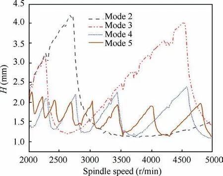
Fig.5 RRUC stability region(AU-L=5 μm,AU-T=3 μm)with different modes (modes 2–5).
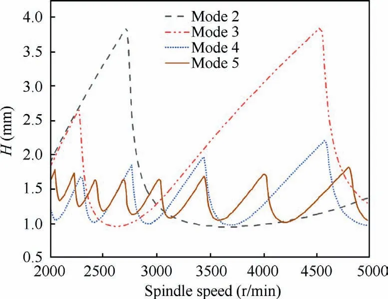
Fig.6 RCC stability region (AU-L = 0 μm, AU-T = 0 μm) with different modes (modes 2–5).

Fig.7 Comparison of stability region with or without ultrasonic amplitude.
As shown in Fig.7,the blue points are the verified machining parameters.Circles represent stable countersinking and crosses mean unstable countersinking.The feed rate per revolution and ultrasonic vibration frequency are 0.02 mm/r and 40 kHz, respectively.It demonstrates that the stability region has a certain improvement with ultrasonic vibration.Compared with the high spindle speed,the improvement of stability boundary curve is greater under the low spindle speed.There is a maximum increase in stability when the spindle speed is 2300 r/min.Under RRUC and RCC, the critical countersinking depth is 1.70 mm and 1.33 mm, respectively.The RRUC stability is improved by 27 %.
4.Experimental verification
In order to verify the accuracy of stability lobe diagram prediction, countersinking experiments are carried out on robotic machining system shown in Fig.8.The RRUC system consists of robotic countersinking system and miniaturized rotary ultrasonic system.Robotic countersinking system includes a KUKA KR500 robot and an end effector.The miniaturized ultrasonic machining system is mounted on end effector.It consists of a non-contact power transmission, a transducer and a horn.During countersinking,the transducer can convert the low-frequency voltage to high-frequency mechanical vibration.Through the horn, the vibration form is changed and amplitude is amplified.Finally, the mechanical vibration is transmitted to the drilling-countersinking tool.In this paper,longitudinal-torsional ultrasonic vibration is used and the ultrasonic vibration frequency is 40 kHz.The longitudinal vibration amplitude is 5 μm and the torsional vibration amplitude is 3 μm.
The influence of the ultrasonic vibration on the robotic countersinking stability is investigated by countersinking carbon fiber reinforced plastic (T700) plate.The plate with size of 280 mm-260 mm-6 mm is fixed via pressing plate on both sides.The drill diameter of drilling-countersinking tool is 4.1 mm, the countersink angle is 100 degrees, and the number of lips is 2.The three-axis accelerometer PCB-356A15 is connected with the spindle in end effector system.The acceleration signal in machining is time-varying recorded.The sampling frequency is 10240 Hz.The spindle of end effector is Renaud 430–120380-HSK32E.The parameter is presented in Table 1.According to the method mentioned in Ref.,51the results of countersinking force coefficients kt, krand kaare shown in Table 2.The modal parameters in robotic countersinking posture are obtained from the frequency response functions(FRFs) measured by standard modal hammering test, as shown in Table 3.As mentioned in Section 3, modes 1–5 are selected to predict the stability lobes.
As shown in Fig.7, twenty points are selected to verify the accuracy of stability region.The stability of each machining point is marked in Fig.7, where circles and crosses are used to indicate whether the system is stable or not, respectively.The red points are in RRUC and the black ones are not in ultrasonic state.In countersinking, chatter is more likely to occur in feeding direction.Therefore, the acceleration signal in feeding direction is selected to determine whether the system is stable.The point 17 in Fig.7 is taken as an example.In RCC and RRUC, the time domain signals and the frequency spectrum after fast Fourier transform(FFT)are drawn respectively in Fig.9.Firstly, from the perspective of time-domain signal,the acceleration value of RRUC is significantly smaller than that of RCC, which means that its fluctuation is smaller and tends to be stable in countersinking.Secondly, from the spectrum analysis,the spindle speed of point 17 is 4000 r/min.The frequency of each order in RRUC spectrum is in rotational frequency and frequency doubling, and there is no large deviation.In RCC, there is a large deviation between 889 Hz and 957 Hz.And the relevant doubling of rotational frequency are 867 Hz and 933 Hz.It indicates that the energy gathers at the frequency doubling of the offset rotational frequency.Meantime, the peak value is much larger than RRUC in the above two order frequencies, which further proves the existence of energy concentration.In summary, RRUC is stable at point 17 while RCC is unstable.
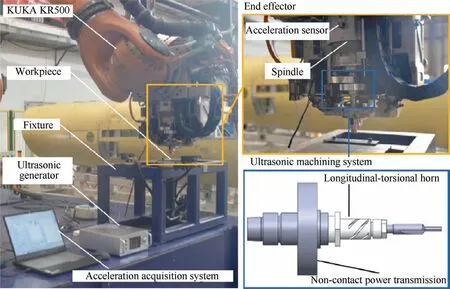
Fig.8 Experimental setup for stability identification.
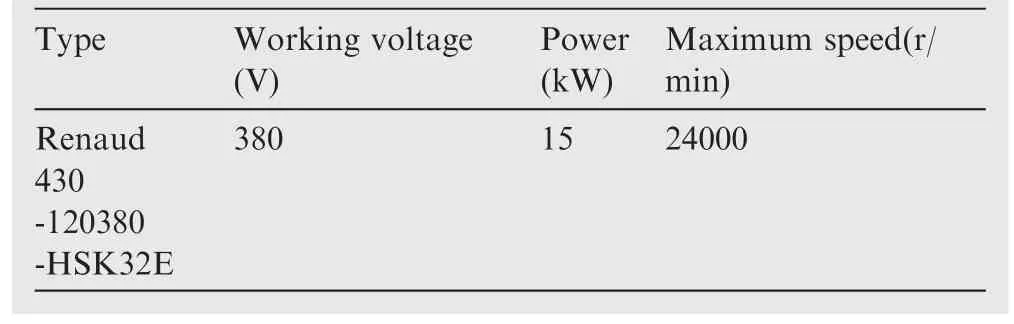
Table 1 Spindle parameter of end effector.

Table 2 Values of countersinking coefficients.
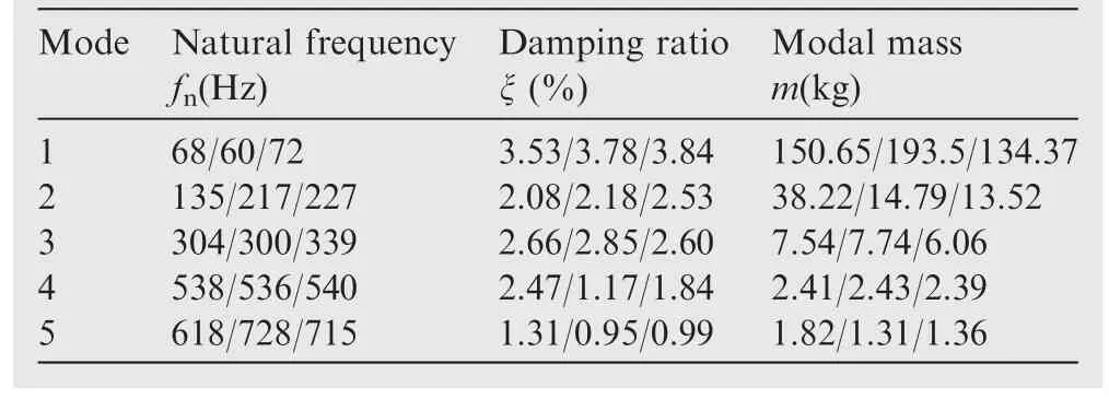
Table 3 Robotic modes in X/Y/Z directions (KUKA KR500).
Through the above method, the stable state of the twenty points is shown in Fig.7.For RRUC, the prediction of the machining state is consistent with the stable lobe diagram.However, the prediction of the state at point 2 is wrong for RCC.It is mainly because the machining parameter is located at the edge of the stable lobe diagram.The accuracy of the prediction cannot be fully guaranteed at this time.In addition to point 2,the stability results of its machining parameters are the same as the theoretical prediction.
5.Discussion
5.1.Reasons for stability region extension of RRUC
Compared with RCC, the stability region of RRUC has a significant improvement, especially at low spindle speed.There are two main reasons.Firstly, the intake of ultrasonic energy changes the direction of external excitation in robotic countersinking.As shown in Fig.3, each force is no longer coaxial with the axis of the original coordinate system OXYZ.There is an ultrasonic function angle (γ) between each force and the original coordinate system.As the force is vector, tangential force, radial force and axial force are mapped to the original coordinate system.And then the vector is added and subtracted.From Fig.3, it can be found that the mapping of tangential force and axial force offsets each other, reducing the size of the external excitation effectively.Thus it makes the stability region of RRUC have a certain improvement.
Secondly,since the form of ultrasonic vibration in this theory is the combination of longitudinal vibration and torsional vibration, torsional vibration and spindle rotation affect each other in a vibration period.In general,the two have the opposite velocity direction at the same time in half of an ultrasonic period, and the other half has the same velocity direction.When the velocity of torsional vibration is opposite to the spindle rotation velocity, its value is greater than that of the spindle rotation.There will be a separation between the tool and workpiece.This phenomenon explains the enhancing effect of ultrasonic vibration at low spindle speed compared to high spindle speed.Under different countersinking depth,the critical separation spindle speed is also different, and the calculation formula can be given as
When the torsional vibration speed is the same as the spindle speed,the cutting speed is faster,which is equivalent to the increase of the spindle speed,so that the material is easier to be removed.It reduces the external excitation generated in material removal and improves the stability of RRUC.
5.2.Effect of ultrasonic parameters on RRUC stability
According to the above analysis, ultrasonic vibration mainly improves the stability region of RRUC by influencing the ultrasonic function angle.This section mainly explores the influence of ultrasonic parameters on the ultrasonic function angle.According to Eq.(5), the parameters which affect the ultrasonic functional angle mainly include ultrasonic frequency FU,longitudinal vibration amplitude AU-Land torsional vibration amplitude AU-T.The variation range is from γminto γmax,which are obtained when the ultrasonic vibration takes the extreme value, respectively, and can be expressed as
To figure out the influence of ultrasonic parameters on stability region,the difference between γmaxand γminis defined as Δγ, which can be expressed as

Fig.11 Effect of different η on Δγ (spindle speed is 4000 r/min,FU = 40 kHz).
As vfis much lower than vrand ultrasonic velocity, it is ignored in computation to simplify computation.Δγ represents the range of ultrasonic functional angle.The larger the Δγ,the larger the shadow area in Fig.3.There is a positive correlation between Δγ and stable region.
Firstly,the influence of ultrasonic frequency and longitudinal vibration amplitude on stability region is explored.As shown in Fig.10, when the spindle speed is 4000 r/min and η is 0.6, different ultrasonic frequency is taken to explore the variation of ultrasonic function angle Δγ under different longitudinal vibration amplitude.With the increase of longitudinal vibration amplitude and ultrasonic frequency, Δγ also has a great improvement.However, when the ultrasonic frequency is large enough, Δγ will increase slowly with the increase of longitudinal ultrasonic amplitude.When the ultrasonic frequency is 10 kHz,there is almost a linear relationship between Δγ and the longitudinal vibration amplitude.And when the ultrasonic frequency is 40 kHz, there is a slow-growth parabolic form, which is no longer a linear relationship.It can be found that both ultrasonic frequency and longitudinal vibration amplitude have a great effect on Δγ.In the case of the same spindle speed and torsional vibration amplitude to longitudinal vibration amplitude, the influence of ultrasonic frequency is greater than the longitudinal vibration ultrasonic amplitude.
When the amplitude of longitudinal vibration is constant,the amplitude of torsional vibration is determined by η.Thus,the effect of torsional vibration amplitude on Δγ is converted to the effect of η.The comparison of Δγ under different η is shown in Fig.11.With the increase of torsional vibration amplitude, Δγ also has an improvement.When η is 0.6, Δγ improves by 10.4 % compared to the case when η is 0.1.
5.3.Effect of modal parameters on stability region
In RRUC, the stability region can be affected by all of modes selected in Table 3.However, different ultrasonic parameters have different effects on each mode.In order to explore the sensitivity of each mode to ultrasonic energy,the stability lobe diagrams of each mode under different ultrasonic parameters are drawn respectively.
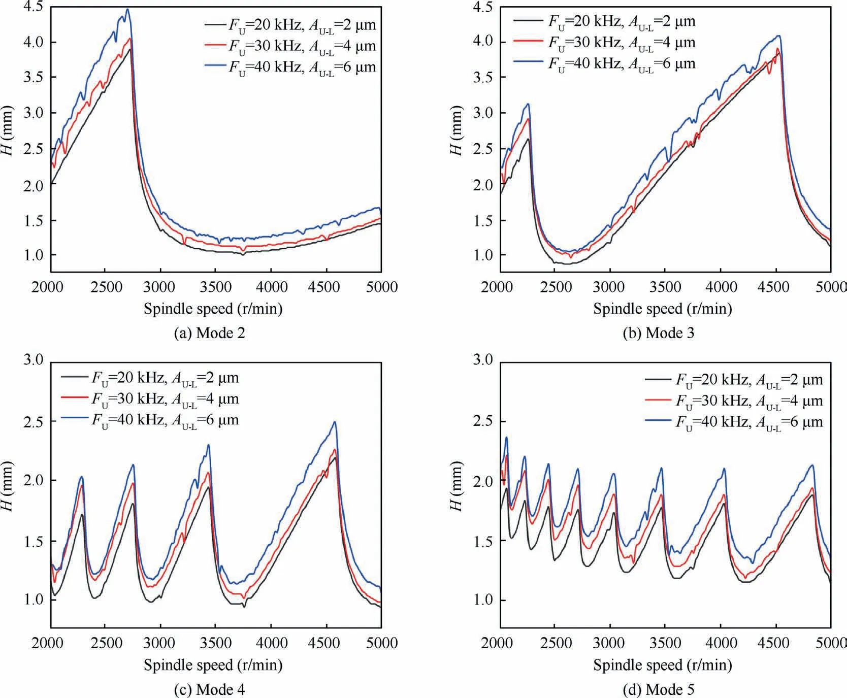
Fig.12 Stability region of each mode (modes 2–5) under different ultrasonic energy (η = 0.6).
As shown in Fig.12, the increase of ultrasonic frequency and amplitude expands the stability lobe diagram in different modes.The area between stability domain curve and horizontal axis is defined to evaluate the improvement of stability lobe diagram.With the increase of ultrasonic energy, the extension radio of stability lobe diagram in different modes are 15.4%,13.4%,17.3%and 18%.According to the results,the stability lobe diagram of mode 5 has the greatest improvement.And the improvement rate of mode 4 is slightly smaller than that of mode 5.As for mode 2 and mode 3, they are relatively insensitive to the increase of ultrasonic parameters.
6.Conclusions
In this paper, a stability analysis method is proposed for robotic rotary ultrasonic countersinking (RRUC) systems.Based on the robotic ultrasonic countersinking carbon fiber reinforced plastic (CFRP-T700) plates, the feasibility of this method is confirmed.According to the prediction model and validation results, three conclusions can be drawn as follows:
(1) This study establishes the RRUC stability model on the basis of the countersinking dynamic analysis.Meanwhile,the experimental results agree with RRUC stability boundary curve well.Compared with robotic conventional countersinking(RCC),the RRUC stability is improved by 27%.
(2) The intake of ultrasonic energy improves the RRUC stability region by changing the tool kinematics.Among them, the reduction of dynamic countersinking force is the direct reason.RRUC stability region enlarges with the growth of the ultrasonic parameters such as the ultrasonic vibration frequency and amplitude.
(3) The stability lobe diagram of RRUC is affected by multi-order modes of robotic countersinking system.With the increase of ultrasonic energy, the extension radio of stability region in various modes are different.The improvement effect in higher order mode is larger than that in lower order mode.
Declaration of Competing Interest
The authors declare that they have no known competing financial interests or personal relationships that could have appeared to influence the work reported in this paper.
Acknowledgements
This study was co-supported by the Project on the Technological Leading Talent Teams Led by Frontiers Science Center for Complex Equipment System Dynamics (No.FSCCESD220401)and the National Natural Science Foundation of China (No.52075265).
 CHINESE JOURNAL OF AERONAUTICS2023年10期
- CHINESE JOURNAL OF AERONAUTICS的其它文章
- Experimental investigation of typical surface treatment effect on velocity fluctuations in turbulent flow around an airfoil
- Oscillation quenching and physical explanation on freeplay-based aeroelastic airfoil in transonic viscous flow
- Difference analysis in terahertz wave propagation in thermochemical nonequilibrium plasma sheath under different hypersonic vehicle shapes
- Flight control of a flying wing aircraft based on circulation control using synthetic jet actuators
- A parametric design method of nanosatellite close-range formation for on-orbit target inspection
- Bandgap formation and low-frequency structural vibration suppression for stiffened plate-type metastructure with general boundary conditions