
Dynamic performance and temperature rising characteristic of a high-speed on/offvalve based on pre-excitation control algorithm
2023-11-10 02:16QiZHONGEnguangXUGengXIEXieleWANGYanbiaoLI
CHINESE JOURNAL OF AERONAUTICS 2023年10期
Qi ZHONG, Enguang XU, Geng XIE, Xiele WANG, Yanbiao LI
College of Mechanical Engineering, Zhejiang University of Technology, Hangzhou 310023, China
Key Laboratory of Special Purpose Equipment and Advanced Processing Technology,Ministry of Education and Zhejiang Province,Zhejiang University of Technology, Hangzhou 310023, China
KEYWORDS
Abstract High speed on/off valve (HSV) is an essential component in aerospace digital hydraulic systems (ADHS).Dynamic performance and temperature rising characteristic are two important features, which determine the performance of HSV, and affect the response speed and reliability of ADHS.Increasing the driving voltage is an effective method for improving the dynamic performance of HSV.However, continuous high voltage excitation will lead to more wasted energy,higher temperature rising and lower reliability.To solve this problem,a pre-excitation control algorithm(PECA)is proposed in this paper based on the theoretical model of the influence of electrical parameters on dynamic performance and temperature rising characteristics.In PECA,an appropriate initial coil current is generated by pre-excitation instead of increasing driving voltage, which significantly shortens the switching delay time.Then, based on real-time current online calculation and feedback mechanism, the adaptive switching of five equivalent voltages is realized.Consequently, the coil current can be rapidly kept at the expected state without consuming more energy and generating more heat.Results indicate that compared with conventional PWM control algorithm, the PECA can improve dynamic performance of HSV, shorten the total switching time by 71.5%, and increase the maximum operation frequency.Therefore, the linear area of flow characteristic is expended by 80.0%, the adjusting time of HSV-controlled system is reduced by 23%,while shortening steady error by 46.7%.Moreover, the temperature rising characteristics of HSV are better, the maximum operation temperature is reduced by 68.6%, and the time to reach the steady state temperature is shortened by 20%.From the results, it can be concluded that the PECA is not only an effective and practical control algorithm for improving the performance of HSVs and HSV-controlled systems while reducing the heat generation and decreasing the temperature rising of HSV, but also can be a potential solution in ADHS.
1.Introduction
Digital hydraulic technology using high speed on/off valve(HSV) to realize fast and precise pressure and flow control,has been widely used in wing rudder controlling,aircraft braking, missile launching, vectoring engine nozzle adjusting and other aerospace hydraulic systems.1,2The reliability and dynamic performance of the aerospace digital hydraulic systems (ADHS) is presented with very stringent requirements due to its extreme application environments, like high temperature, strong pressure and great acceleration.3The dynamic performance of HSV, an important digital hydraulic component, is the key to improving the response speed and control accuracy of the ADHS, and reducing the temperature rising can significantly optimize the energy saving feature and reliability of HSV.4,5Therefore,dynamic performance and temperature rising characteristics are indispensable for HSV, and become the research hotspots in the field of aerospace digital hydraulic technology.6,7
Considerable research has been carried out to improve the dynamic performance of HSVs in the ADHS.Ruan et al.proposed a new structure of on/off valve, whose switching operation was realized by the high-speed rotation of the spool inside the sleeve.8Based on this structure, Meng et al.proposed a novel two-dimensional maglev valve, which introduces a contactless maglev coupling between the electromechanical converter and valve body.5The results show that the no-load flow rate can reach 105.9 L/min with a hysteresis of 3.51%, an amplitude bandwidth of 28.7 Hz, and a phase bandwidth of 42.8 Hz under 21 MPa, which meets the requirements of high pressure and large flow rate in civil aircraft flight control surface systems.Li et al.designed an adaptive simulated annealing algorithm to optimize coil turns,spool mass, working air gap width and model tube diameter of aviation HSV, which shortened the opening response time by 50% and the closing response time by 45.4%, further improving the performance of aero engines.9Moreover, to meet the high endurance and strong stability requirements of aero engines, Mahajan et al.introduced flux routers at appropriate locations in the solenoid geometry to divert the unused magnetic force to the working air gap.10Due to the very high force-to-weight ratio of the solenoid in a limited stroke, this method not only increases the mechanical force by 10% - 40%, but also speeds up the opening movement of HSV.Furthermore,some non-conventional actuators were adopted in the HSV to meet the stringent requirements of ADHS.For example, the dielectric elastomer was applied to drive the HSV, and a fast response was realized.11Man et al.presented a permanent-magnet shield for highpressure applications, as a result, the dynamic characteristic of the HSV was greatly improved.12Zhu and Li developed a deflector-jet valve using a piece of giant magneto strictive material with a large output pressure range, fast response time and high bandwidth.13
The above studies focused on the design of mechanical structure or manufacturing processes of HSVs.However, for the existing HSVs, optimizing the control algorithm was proved as an economical strategy to improve the dynamic performance and reduce the temperature rising.14Huang et al.designed an aircraft braking system based on HSV flow control,which regulates the flow of the brake cylinder by adjusting the duty cycle of the PWM signal,thus realizing the control of the braking pressure.15To further improve the efficiency of the braking system, Sun et al.proposed an antiskid control algorithm based on HSV array, which updates the driving frequency and duty cycle of HSV in real time through a closed-loop controller.16The HSV array has good flow characteristics under high frequency switching, so as to achieve a braking efficiency of 90.72% in a dry runway environment.To improve the accuracy and efficiency of pitch and yaw attitude control of the rocket secondary main engine, Yao et al.designed a digital flow distribution type electro-hydrostatic actuator, which achieved high-precision position control of the actuator through two HSVs to realize asymmetric flow compensation and micro-flow regulation of the system.17Tang et al.proposed a control algorithm based on a time prediction model to achieve independent control of the two chambers of the hydraulic cylinder by four HSVs, thus improving the control accuracy of the position.18Most of the above studies applied composite control algorithms to improve the dynamic performance of the HSV, thus enhancing the response speed and control accuracy of the ADHS.However, the whole control process requires sufficient time for command reading,system operation, control output and component execution,resulting in a limited switch frequency of the HSV.Therefore,directly adjusting the driving voltage of the HSV can further shorten the control cycle and improve the dynamic performance of the HSV.
The influence of driving voltage on the maximum electromagnetic force of a solenoid valve was analysed, and the conclusion that increasing the driving voltage was beneficial for improving the dynamic performance was obtained.19,20Xiong and Huang adopted the peak and hold technique to improve the dynamic performance of HSV.21Lu et al.presented a pre-energizing control strategy based on a dual power supply,and the effects of current on switching response of an HSV were analysed.22However, the method of dual power supply had high requirements on the circuit, and there were risks of short circuit or current overshoot, which was not suitable for industrial applications.A self-correcting PWM control algorithm was proposed in Ref.23,24, to improve and stabilize the HSVs’ dynamic performance under changing pressures.On this basis, Zhong et al.presented a multi-voltage compound algorithm to improve the dynamic performance of HSV.25Nevertheless, this algorithm required to switch among five independent voltage sources, so it is extremely demanding on the hardware circuitry and further constrained the frequency response characteristic of the HSV.Cheng et al.investigated the relationship between the dynamic response and temperature rising characteristic of the HSV in the pre-energizing control strategy.26
Increasing the driving voltage was found to be effective to improve the dynamic performance of HSV.27However, a larger driving voltage will inevitably lead to more energy loss,higher temperature rising and lower reliability.In addition,the dynamic characteristics of solenoid valve are affected by switching delay time and switching moving time.Most studies focus on the total time, the sum of the delay time and moving time.However, few studies have focused on reducing the switching delay time,which has a major effect on the response characteristics of HSV.The aim of this paper is to improve the dynamic performance and reduce temperature rising of HSV without increasing the driving voltage, so as to better the performance of the ADHS and increase the reliability and service life of HSV.
A pre-excitation control algorithm(PECA) based on a single voltage source is proposed to improve the dynamic performance of HSV.The control cycle for HSV operation consists of five stages,each of which is driven by an equivalent voltage generated by a high-frequency PWM voltage signal.Based on the current feedback mechanism and digital signal logic triggering principle, the adaptive switching of the five equivalent voltages is realized, which makes the current control more accurate.PECA ensures the current very close to the critical switching current, so as to shorten the switching delay time and accelerates the switching process without increasing the driving voltage.A commercial HSV is selected as the research object, the mathematical model of the selected valve is established,and the theoretical formulas for the delay characteristic and temperature rising feature of the HSV are deduced.Numerical and experimental studies demonstrate the effectiveness of PECA.
Compared with the existing driving algorithm of HSV,PECA not only improves dynamic characteristic,and enhances flow characteristic of the HSV, but also reduces the temperature rising of the solenoid and increases the reliability of HSV.Therefore, PECA can be a promising solution in some ADHS, such as aircraft braking, wing rudder controlling,and missile launching.
2.HSV mode
2.1.HSV introduction
This paper selects a commercial HSV as the research object,which is a normal closed ball structure with two-position and three-way, as shown in Fig.1.
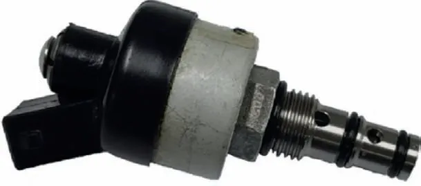
Fig.1 Experimental HSV.
The structure of this HSV is firstly introduced in Ref.23,as shown in Fig.2.Different from the traditional HSVs with return spring, this HSV recovers through the hydraulic pressure from port P.As solenoid is energized, electromagnetic force overcomes the pressure of hydraulic through port P, so armature pushes two operation spheres to the left.At this time,the HSV operates at ‘on’ state, as shown in Fig.2(a).Conversely, as solenoid is de-energized, two operation spheres are turned to the right, and HSV operates at ‘off’ state, as shown in Fig.2(b).
2.2.Mathematical modelling
The working process of the HSV is always accompanied by the coupling of electric–magnetic-mechanical-fluid fields,28and its energy conversion process can be described as Fig.3.Therefore, the mathematical analysis of this HSV is composed of the dynamic models of each field.
2.2.1.Electrical field
In the electrical field, HSV’s behaviour of HSV is given by
where U represents the driving voltage, R denotes the equivalent resistance, I is the coil current and L denotes the equivalent inductance.
2.2.2.Magnetic field
For magnetic field analysis, the equivalent magnetic circuit(EMC) method is adopted to analyze the magnetic flux of HSV.29,30To ensure the accuracy of EMC model, a finite element analysis(FEA)model was established to study the distribution of magnetic flux under different air gaps and excitation currents,as shown in Fig.4.It can be found that the distributions of magnetic flux are approximate under different conditions.Therefore, the solenoid under different operation conditions can be analyzed by the same EMC model,as shown in Fig.5(b).The symbol definitions are as follow:denotes the reluctance of equivalent magnetic.Symbol i indicates reluctance numbers.Symbol * stands for different parts of HSV.Symbol a,g,f represent armature,air gap and magnetic frame,respectively.Since non-magnetic frame and air gap have the same permeability, so both of them are grouped into one category in the calculation,F is magnetic potential,ɸiis magnetic flux in magnetic circuit branch i.
The magnetic potential is given by
where N means the coil number.
The integral expression of reluctance can be expressed as
where l indicates the path length of magnaflux,S stands for the cross-sectional area of magnaflux path,and μ means the materials permeability.
According to the geometry of HSV and the path of magnetic flux, the calculation models of reluctances can be composed of three parts: the model of axial cylinder, radial cylinder and normal ellipse ring respectively.Combined with Eq.(3), the equations of each model are shown in Table 1.
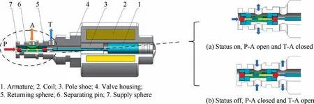
Fig.2 Structure of experimental HSV.23
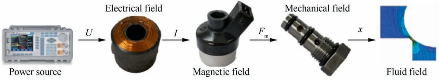
Fig.3 Energy conversion of HSV.
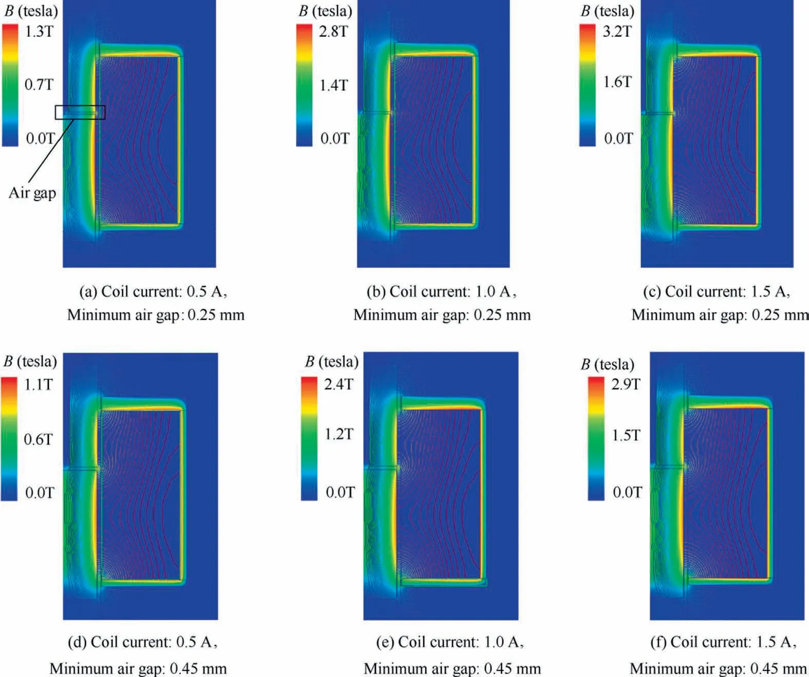
Fig.4 Magnetic finite-element analysis of HSV.
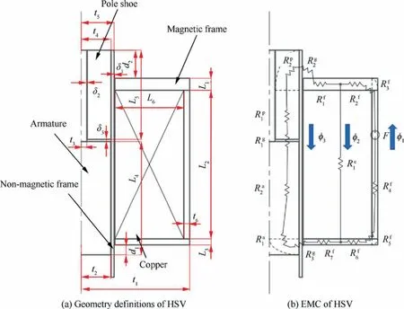
Fig.5 Simplified model of HSV.

Table 1 Calculation model of reluctances [27].
The equivalent reluctances of each magnetic circuit branch are given by
where Rmidenotes equivalent reluctance of magnetic circuit branch i.Rmdenotes equivalent reluctance of total magnetic circuit.
Magnetic flux is given by
Under the action of the solenoid, its electromagnetic force can be expressed as
where Fmis the force of electromagnetic, μ0represents the air permeability, and Sgdenotes the air gap cross-sectional area.
The solenoid inductance can be expressed as
2.2.3.Mechanical field
Considering the influence of the electromagnetic force, flow force, damping force, and reset hydraulic pressure on the dynamic performance, the kinematic equation of HSV can be expressed as
where m is the moving part mass, Ftand Fsstand for the hydraulic force of transient and steady-state, respectively.k denotes the friction coefficient, Psrepresents the pressure of supply, A denotes the effective cross-sectional area of the port P,x means the moving parts displacement,and t represents the time.
2.2.4.Fluid field
As fluid momentum changes, the steady flow force always drives the HSV to close, and is characterized as
where Cvand Cfstand by the coefficient of fluid velocity and flow, respectively.Aostands for open orifice area, θ indicates the angle of flow, and ΔP denotes the drop in pressure across the orifice.
Flow force in a transient is given by
where Ldstands for the length of damping, ρoindicates the density of oil, and w represents the area gradient.
During the critical moment of movement(when the spheres are about to move, but still remains stationary), the acceleration and velocity are both zero.Hence,the critical electromagnetic force can be deduced as
where Fcmis the force of critical electromagnetic, and Fsis determined by the direction of the flow.
As HSV in the ‘off’ state, the flow force is in reverse direction of the hydraulic pressure, so Eq.(16) is further expressed as:
where PATrepresents the difference in pressure between port T and port A.
While HSV in the‘on’state,the flow force is consistent with the direction of the hydraulic pressure,thus the Eq.(16)is further expressed as
where PPAmeans the drop in pressure between port A and port P.
2.2.5.Temperature field
Energy loss is inevitable in the coupling process of each field,which cause a temperature rising of the HSV.The main sources of heat are solenoid copper loss and eddy current loss.31
The solenoid copper loss is caused by the flowing coil current.The equation is as follows:
where Pcldenotes solenoid copper loss.
The eddy current loss is caused by the current which is induced by a changing magnetic field flowing in the armature.The equation is as follows:
where Pelmeans the eddy current loss, Ceddydenotes the eddy current loss coefficient, f represents the frequency of magnetic field, Bmdenotes the magnitude of the magnetic induction intensity in the armature,d is the armature diameter,ρmstands for the electrical resistivity of the material.
The amplitude of the magnetic induction intensity in the armature can be obtained by:
where φ3denotes the magnetic flux of magnetic circuit branch 3 in Fig.5(b).
According to Eqs.(8)and(10),the eddy current loss can be expressed as
where Iedenotes the equivalent current of the changing operating current in the coil.
Thermal convection occurs when the temperature of HSV is different from that of the environment.The heat from the HSV will be transmitted into the air.The heat exchange power can be expressed by
where Phcis the heat exchange power, h denotes convective heat transfer coefficient, THSVrepresents the HSV temperature, T means the ambient temperature, and SHSVstands for the surface area of HSV.
The transient heat power can be expressed as
where Phdenotes the transient heat power of HSV.
The transient heat power is 0 as the temperature of HSV reaches the steady state, thus, according to Eqs.(23) and(24), the steady state temperature of HSV can be deduced as
where Tstdenotes the steady state temperature of HSV.
2.2.6.Analysis of dynamic characteristic
Combining with the Eqs.(2),(8),(10),(11),(12),(17)and(18),the critical currents which include the opening current(switching on) and closing current (switching off) can be deduced as
where Ionand Ioffstand for the critical current of the opening and closing stages,respectively.Similarly,Lonand Loffare the equivalent inductances as HSV operates in the ‘on’ and ‘off’states, respectively.When solenoid is in static operation, its equivalent inductance is kept constant, which is determined by Eq.(12).
The opening time tonis the time from the control signal rising edge to the fully opened moment of the valve.The opening process is composed by the opening delay time and the opening moving stage.The opening delay time is the moment between the control signal rising edge and the current of critical opening (the time as armature starts moving).During the opening process, coil current has the following transient characteristics:
where Iionis the initial current during the opening process,and Roffmeans the equivalent resistance when HSV operates at status off.Hence, the opening delay time of the HSV is given by
where tdonmeans the opening delay time.
The second stage is the moving stage,in which the armature starts to move until it reaches the maximum stroke.Since the stroke is very short,the velocity of the armature in the opening moving stage is limited.Therefore, a uniform acceleration can be considered to describe the opening moving process:
where aon=(Fm-PsA)/m, dsrepresents the stroke, and tmondenotes the time of opening moving.
The closing time toffis defined as the time during the control signal falling edge until the valve is completely closed.The closing phase contains closing delay stage and closing moving stage.Similarly, the closing delay time is defined as the time during the control signal falling edge until the current reduces to the critical closing current(the moment when armature starts resetting).The current in the closing delay stage can be presented as
where Ronis the equivalent resistance during the opening stage, and Iioffmeans initial closing current.
The closing delay time can be calculated by
The closing moving stage is the time of armature starts to reset until the valve is full closed.With the same reason of short stroke, the closing time can also be calculated by a uniform accelerate process:
where aoff= (PsA- Fm)/m, and tmoffis the closing moving time.
Combining the Eqs.(19),(22),(25),(29),(30),(32)and(33),the following conclusions can be drawn:
1) Small current can effectively reduce solenoid copper loss, eddy current loss, and HSV working temperature under the same operating frequency.
2) Large driving voltage and initial current in opening process are helpful to reduce opening delay time.
3) Small driving voltage and initial current in closing process are effective in reducing closing delay time.
4) Negative driving voltage is more conducive for rapidly decreasing the current to improve the closing dynamic performance.
Therefore,the driving voltage and initial current are the key factors to affect the dynamic characteristic of HSV.Generating an ideal initial current which is very close to the critical switching current before the switching moment is an effective method to shorten the delay time and improve the dynamic performance of HSV.In addition, remaining the current as low as possible in each stage is a practical method to reduce the temperature rising of HSV.
3.Operation principle of PECA
To enhance the dynamic characteristic of HSV without increasing the driving voltage, the PECA is presented.PECA is a logic-based control strategy,which realizes precise control of each working state of HSV through current feedback, and has the following advantages:
1) The dynamic performance of HSV can be significantly improved.
2) With detailed theoretical derivation, the current-based judgment makes the strategy more flexible and stable.
3) The control strategy is simple and easy to popularize and apply in industrial environment.
4) Lower hardware performance requirements and costs.
The hardware implementation of PECA is illustrated in Fig.6.The control signal consists of two parts: operating frequency and driving duty ratio.The controller enables the generation of five high-frequency square waves with different duty ratios, thus guaranteeing a more refined driving of HSV.The circuit current is measured by the current detector, which is used to analyse the operation status of the HSV according to the comparison of the critical switching current.
The control algorithm precisely divides each operating cycle of HSV into five stages, represented by numbers ①to ⑤in Fig.7(b),maintaining closed stage,pre-opening stage,opening stage, pre-closing stage and closing stage.The controller provides a high-frequency PWM voltage signal to drive the HSV corresponding to each duty ratio.Moreover, Fig.7(b) also illustrates the duty ratios selection rules for each stage.There is a PWM voltage signal with an opening pre-duty ratio during the pre-opening stage,a duty ratio of 100%during the opening stage, a closing pre-duty ratio during the pre-closing stage, a duty ratio of-100%during the closing stage,and a duty ratio of 0% during the closed stage.The voltage signal with an opening pre-duty ratio is used to generate an initial current before the opening stage.Therefore, to decrease the opening delay time and keep the HSV off, product of the equivalent resistance R and critical closing current Ionis slightly larger than product of source voltage and opening pre-duty ratio.A similar approach is used to shorten the closing delay time while keeping the HSV on.Note that product of R and Ioffis marginally smaller than product of the source voltage and closing pre-duty ratio.
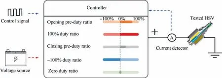
Fig.6 Hardware implementation of PECA.
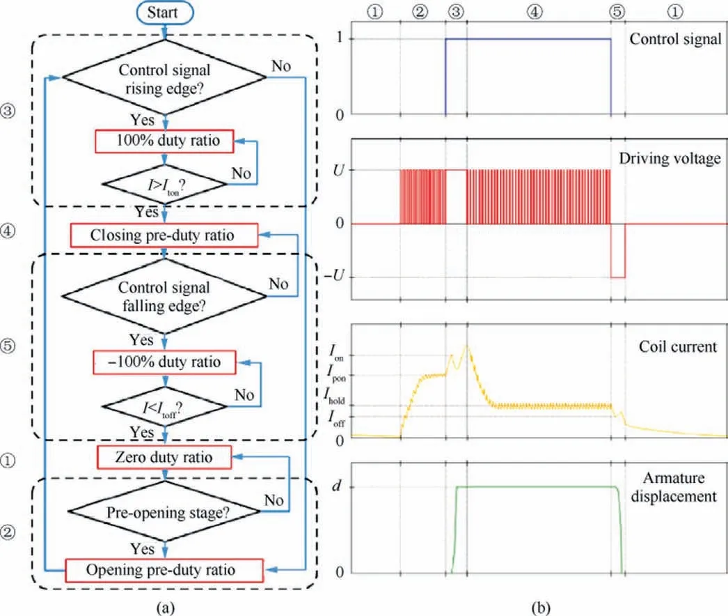
Fig.7 Operation principle and effect of PECA.
The operation principal diagram of PECA is detailed in Fig.7(a), and its effect is illustrated in Fig.7(b).Itonand Itoffdenote the current trigger value during the opening and closing stages,respectively.To guarantee full switching of HSV,Itonis slightly larger than the critical opening current Ion.Moreover,Itoffis marginally smaller than the critical closing current Ioff.
The system starts from fully closed stage ①.The preopening excitation time is calculated by the controller according to Eq.(29),which is the time for the current to increase to the pre-opening current Ipon(slightly smaller than the critical opening current Ion).Pre-opening stage ②should be slightly longer than calculated pre-opening excitation time to ensure the current can reach the pre-opening current, so as to determine the trigger time of the pre-opening stage ②.Therefore,when the moment for pre-opening stage ②comes, the controller drives the HSV with the opening pre-duty ratio to build an initial current for the next opening stage.
Combining with the appropriate excitation time and duty ratio for pre-opening stage ②,the current increases and finally maintains at the value of Ipon(pre-opening current).When the control signal rising edge comes, the controller generates a 100%duty ratio voltage signal in the opening stage ③,thereby rapidly increasing the current.Because of the initial current Iponand maximum voltage value, the current reaches the trigger value Itonin a very short time.During the whole preclosing stage ④, the HSV is completely open, and the controller drives it with the closing pre-duty ratio.
Under a closing voltage of closing pre-duty ratio, the current will eventually fluctuate slightly at the value of Ihold(holding current), which is marginally larger than Ioffto keep HSV open until the control signal falling edge occurs.Then the controller drives HSV at the duty ratio of-100%during the closing stage ⑤, causing the current to drop rapidly until it reduces Itoff.At this time, HSV is completely closed and the controller switches to 0%duty ratio again for the maintaining closed stage ①, thus enabling the current to reduce gradually.Moreover, the controller calculates pre-opening excitation time for the next pre-opening stage ②according to current situation.
PECA provides the ideal initial current, which is less than the critical opening current during the opening stage, while slightly greater than the critical closing current during the closing process.PECA adopts maximum positive voltage and negative voltage to speed up the current dynamic process, so that the time required for the current to reach the trigger value can be further reduced.PECA adaptively adapts the switching moments of the five duty ratios, so that the current status can be rapidly controlled to a desired value.Therefore, PECA can greatly improve the entire switching behaviour of the HSV without increasing the driving voltage, which depends mainly on the current.Because the current is slightly higher or lower than the necessary current throughout the opening stage and pre-closing stage, heat generation will be greatly reduced.
4.Simulation analysis
The performance of the solenoid in this model was defined by its force and inductance characteristics, which were the results of electromagnetic field analysis of the solenoid,as depicted in Fig.8 and Fig.9.Some critical parameters of the studied HSV were obtained by experimental measurements, as presented in Table 2.
To show the superiority of the PECA, the conventional PWM (CPWM) excitation method and the self-correcting PWM control method of dynamic performance preservation(SCDPP) are used for comparison.11,23The CPWM is one of the most popular industrial driving methods for HSVs.And the SCDPP has the advantages of excellent dynamic performance and maintaining stable dynamic performance under variable pressure conditions.The two driving strategies are shown in Fig.10.When the CPWM is in the opening delay stage,opening stage,and opened stage,it applies high voltage;when it is in the closing delay stage, closing stage, and closed stage, it applies zero voltage.Different from the CPWM, the SCDPP applies modulated high frequency PWM in the opened stage (maintenance stage), and applies reverse high voltage in closing delay stage and closing stage.
In the dynamic performance simulation analysis,the values of the voltage source in PECA,CPWM and SCDPP are set as 24 V.The supply pressure in the simulation is set as 20 MPa,which is the rated hydraulic pressure.The switching dynamic performance and current characteristic of HSV at 20 Hz control signal and 50%duty ratio are shown in Fig.11.The rising and falling edges of the control signal are at 100 ms and 125 ms respectively.
From Fig.11(a),it can be illustrated that due to ideal initial currents generated by the pre-excitation function, the opening delay time of the HSV driven by PECA are greatly shortened to 0.4 ms, compared to the CPWM and SCDPP.The opening delay time of the HSV driven by CPWM and SCDPP are 2.5 ms and 3.0 ms respectively.The three driving methods adopt the same driving voltage of 24 V, so opening moving time in these driving methods are both 1.7 ms.
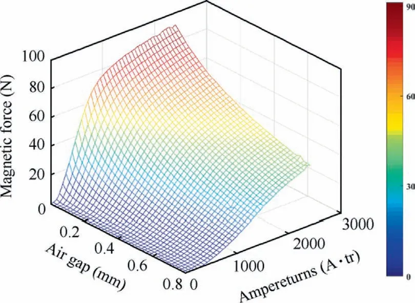
Fig.8 Magnetic force characteristic of solenoid.
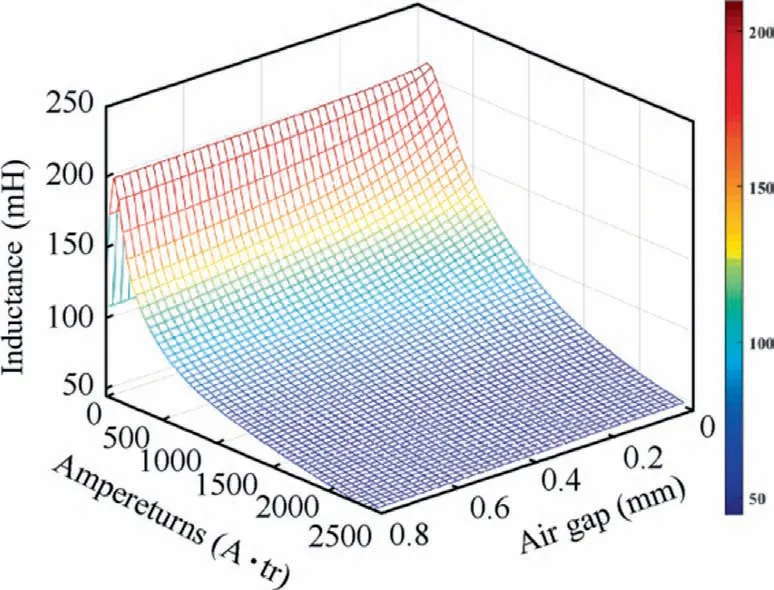
Fig.9 Inductance characteristic of solenoid.
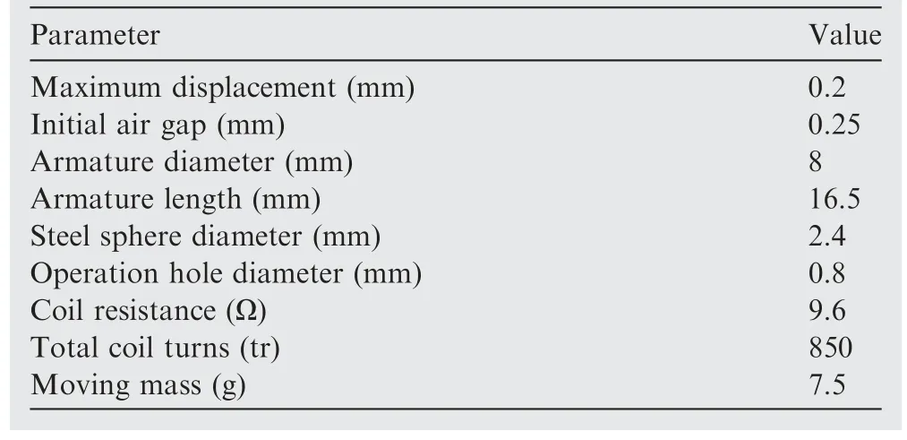
Table 2 Structure parameters of researched HSV.
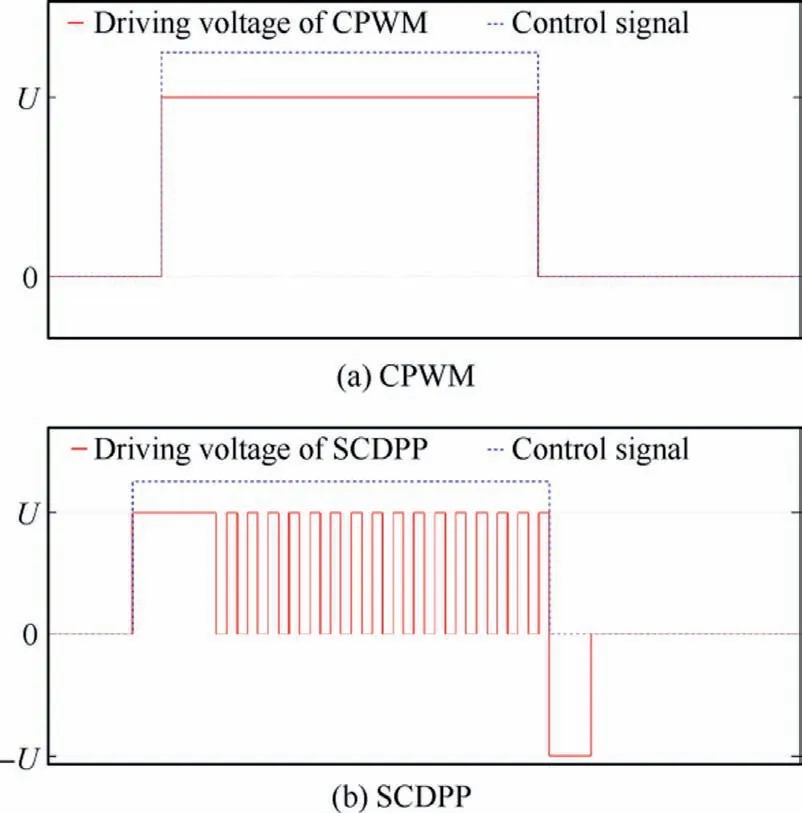
Fig.10 Control strategy of CPWM and SCDPP.
During the closing stage of HSV as shown in Fig.11(b),the delay time and moving time in CPWM are 6.7 ms and 6.0 ms respectively, which are greatly longer than that in PECA and SCDPP.Because in the PECA and SCDPP, the preexcitation function is adopted to decrease the initial closing current, and a reverse voltage is applied to accelerate the current drop and HSV closing.The closing characteristics of the PECA and the SCDPP are similar.the closing delay times and moving times are both 0.1 ms and 1.6 ms in the two strategies.

Fig.11 Dynamic performance simulation results.
5.Experiment results and discussion
5.1.Design of experiment system
The compact structure of HSV makes it difficult to measure the displacement of the spool directly.In addition, the installation of displacement sensors undoubtedly increases the weight of moving parts, which affects the characteristic of HSV.Therefore, a pressure dynamic response measurement method was found to be effective to test the switching performance of the HSV,32as shown in Fig.12.When the HSV is opened, the port A is linked to the port P, and the pressure in the testing chamber will rise to the supply pressure.Conversely, when the HSV is closed, the testing chamber is connected to the tank, and the pressure decreases to that of the tank.
However, the pressure response is sensitive to the testing chamber volume.33As the testing chamber volume decreases,the dynamic response of pressure will be faster.Therefore, a thin-film sputtering pressure sensor as shown in Fig.12(b) is used in this paper,which makes the test chamber volume minimal and thus improves the measurement accuracy.
A FPGA controller (NI cRIO-9035) is applied to implement PECA and CPWM.The NI 9505 driver board generates high frequency square waves,and detect the current status and provide it as feedback to the controller.In addition, the NI 9205 driver board collects feedback data from thin-film sputtering pressure sensor, and its test system is illustrated in Fig.13.
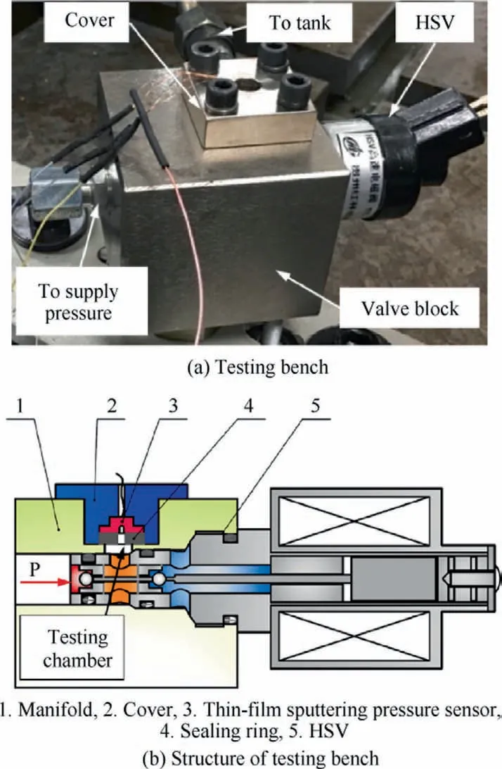
Fig.12 Dynamic performance testing bench and its structure.
The power source for the HSV is also set to 24 V.From the static measurement experiment, the critical opening current is 0.84 A, and critical closing current is 0.33 A under the 20 MPa operation conditions.To guarantee that the HSV is totally switched,the trigger values Itonand Itoffare determined to be 1.0 A and 0.1 A, respectively.The pre-opening current Ipon, holding current Ihold, opening pre-duty ratio and closing pre-duty ratio are set as 0.75 A, 0.40 A, 30% and 16%,respectively.
5.2.Switching response experiments
The results of the dynamic performance experiment run in CPWM and SCDPP are presented in Fig.14.According to the curves in Fig.14(a),the delay time and moving time during the opening stage are both 2.8 ms.For the closing process,poor dynamic performance can be observed as shown in Fig.14(b), with delay time and moving time of 7.9 ms and 7.6 ms, respectively.
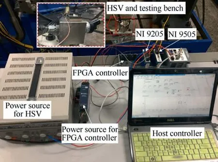
Fig.13 Experimental system photo.
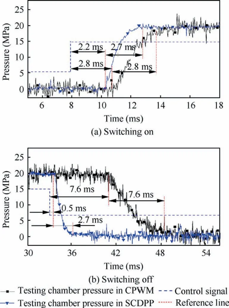
Fig.14 Dynamic performance in CPWM and SCDPP.
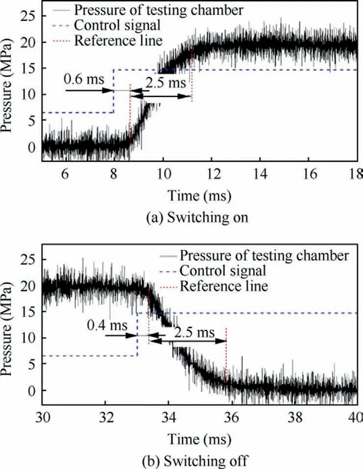
Fig.15 Dynamic performance in PECA.
Under the action of the CPWM,the current increases to the maximum achievable value of 2.5 A when the HSV is opened,resulting in a large initial current at the moment of closing and eventually prolonging the closing delay process.In addition,the current drops naturally under zero voltage, causing a slower decreasing of the magnetic force.In this way, the combined force acting on the moving parts increases slowly correspondingly, making the acceleration of the moving parts smaller and further increasing the moving time in the closing stage.
Fig.15 illustrates the switching behaviours of HSV driven by PECA.The experimental results are in agreement with the simulation results.The delay times of switching on and switching off are shortened greatly to 0.6 ms and 0.4 ms,respectively.Under the pre-excitation function of PECA, the current is kept at a value slightly below the critical opening current until the switching on moment and at a value slightly above the critical closing current until the switching off moment.Combining with maximum positive excitation of 24 V in the opening stage ③and maximum negative excitation of-24 V in the closing stage ⑤,the current can reach the critical switching value in a very short time, so that a smaller switching delay time will be ensured.
Because of the same driving voltage during the opening moving process, the opening moving characteristic in PECA behaves almost the same as the opening moving performance with CPWM, and the opening moving time remains at 2.5 ms.The unloading function of the -24 V voltage accelerates the dropping process of the current and makes the resultant force acting on the moving parts increase rapidly.As a result, the closing moving time is shortened to 2.5 ms.Additionally, according to the experimental results of Eq.(23),the PECA has better dynamic performance than SCDPP method.
5.3.Frequency response characteristic experiments
The frequency response characteristic of HSV is investigated under the action of CPWM and PECA, respectively.The frequency and duty ratio of control signal are set as 50 Hz and 50%, respectively.The results of CPWM are presented in Fig.16.Both simulation results and experiment results indicate that the HSV is not able to be fully closed.This is because the dynamic performance for an HSV in the closing stage is worse than the response in opening stage.As a result,the time required for a closing process will be longer than an opening process.Therefore, when the expected closing duration (control signal remains low)is reduced to less than tdoff,the HSV is not going to close.When the expected closing duration is in the zone of[tdoff,tdoff+ tmoff], (tmoffis closing moving time of the HSV),the HSV will move towards the closing direction, but cannot be completely closed.When the expected closing duration is larger than tdoff+tmoff,the HSV can be completely closed.
The curves in the Fig.16 illustrated an HSV operating under a critical state, where 50 Hz is the limit switching frequency.However, if the target control frequency continues to increase, the HSV will not move to close, but remain open all the times.
The frequency response performance of the HSV driven by the PECA is shown in Fig.17.It is observed that the HSV can switch to track a control signal of 50 Hz and 50 % duty ratio with reasonable accuracy.Results show that the fully opened time of the HSV in each operation cycle reaches to about 8.00 ms, and the totally closed time keeps at 8.44 ms.Therefore, the total switching time of the whole operation time is 82.2%, and the actual operation duty cycle of the HSV achieves to 48.7%, which is close to the target operation duty ratio of 50%.
According to pressure dynamic characteristic of the testing chamber, it is observable that the HSV can easily follow the target switching signal, and PECA has great potential to enable the HSV to operate with higher switching frequency.The PECA can effectively improve the maximum operation frequency of the HSV, which is the most important characteristic of the HSV.This feature ensures better control accuracy of an HSV controlled system.
Due to the pressure change in the test chamber which lags behind the spool displacement, there is a slight delay phenomenon between the experimental results and the simulation results.
5.4.Flow characteristic experiments
Due to the improved dynamic performance of HSV,especially its delay characteristic, the flow characteristic of HSV is also improved.Under the test condition of 20 MPa supply pressure,and 20 Hz control signal frequency, the flow characteristic is shown in Fig.18.From the curves, it can be found that the simulation results are well matched with the experiment results, which further proves the accuracy of the simulation model.
In the CPWM, when the control signal duty ratio is less than 7 %, the HSV operates in the dead zone and remains closed.When the duty ratio increases to 7% to 15%, the flow is in a nonlinear region, which means the HSV starts to open,but cannot reach a full open stage.In the duty ratio range from 15% to 65%, the flow characteristic is in linear area, and the HSV can fully switch.When the duty ratio increases from 65% to 77%, the flow shows nonlinear characteristic again,which means the HSV cannot be closed completely.When the duty ration is larger than 77%, the HSV operates in the saturation status.Because the closing delay time is much longer than the opening delay time in CPWM,so that the flow curve deviates from the centre position (50% duty ratio, 50%Q/Qmaxin the picture) and shifts to the left side.
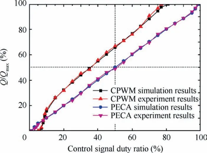
Fig.18 Flow characteristic of HSV.
When the PECA is applied, the flow characteristic of the HSV becomes much better.The results show good linearity in the duty ratio range from 5% to 95%, and the curves are perfectly centrosymmetric.It is demonstrated that when the driving voltage is the same, PECA method provides a wider range of linear operation duty ratio.Compared with CPWM method,it is expanded by 80%,which ensures a better proportional characteristic between control signal duty ratio and the corresponding output flow.
5.5.Temperature rising experiments
In this experiment, the HSV was placed in an environment with a room temperature of 20 ℃, and driven by the CPWM and PECA respectively.The driving voltage was 24 V, the operating frequency was 20 Hz, and the duty ratio was 50%.In order to guarantee the measurement accuracy,a thermal imaging instrument was applied to measure the overall temperature distribution of the HSV, and the result was shown in Fig.19 (a heating platform with a constant temperature of 100 ℃was placed beside the HSV for contrast).It is clearly seen that the solenoid is the heat source,which is the maximum temperature area in the HSV.
The temperature of solenoid was measured by infrared thermometer to obtain the maximum temperature variation characteristics of HSV.The results are shown in Fig.20.It is easy to find that the maximum temperature of HSV driven by CPWM reached a steady state around 21 minutes, and the steady state temperature was 110.0 ℃.However,the steady state temperature of HSV driven by PECA was only 34.5 ℃,and the time to reach steady state was also shortened to 16 minutes.Compared with CPWM,the steady state temperature of HSV driven by PECA was greatly reduced by 68.6%(75.5 ℃),and the time to reach steady state was also shortened by 23.8% (5 minutes).
The simulation results are in good agreement with the experimental results, and the trend is consistent, which proves the correctness of the temperature rise model.The conclusion can be obtained that PECA has a lower temperature rising than CPWM, which can effectively improve the reliability and extend the service life of HSV.This is because the piecewise driving of PECA ensures the current of solenoid to be accurately controlled within the necessary range.The average current of the HSV driven by PECA is much smaller than the current of the HSV driven by CPWM.Therefore, the heat generation of the solenoid is greatly reduced, the temperature characteristic of HSV is improved and the operation temperature is decreased.

Fig.19 Temperature distribution of HSV.

Fig.20 Maximum temperature change of HSV.
5.6.Discussion
In summary of the presented mathematical evaluation, simulation analysis and experimental comparison, the results indicate thatthe PECAcaneffectivelyoptimizethe switching delay behaviors of the HSV,improve its dynamic characteristic,increase its maximum operation frequency,and better its flow control performance without increasing the driving voltage,while optimizingits temperature rising characteristics and reducing the operation temperature.Moreover,the dynamic performance of HSV determines the response speed of ADHS, and its temperature rising characteristics affect the reliability of ADHS.
Compared with CPWM, the developed PECA has clear advantages in improving the comprehensive performance of HSV.A reduction of 78.6% (2.22 ms), 10.7% (0.33 ms),94.9%(7.59 ms)and 67.1%(5.1 ms)is achieved in the opening delay,opening moving,closing delay,and closing moving time of the HSV, respectively.Hence, the total switching time has been shortened by 71.5% (15.1 ms).The maximum operation frequency is improved greatly.The range of the controllable duty ratio and the linear area of flow characteristic curve are expended by 58.3% and 80.0%, respectively.The temperature rising of the HSV is also reduced by 68.6%.
There are two main factors contributing to the experimental error of the switching response.One of them is the steadystate flow force, which exists only in simulation models.Nevertheless,as illustrated in Fig.12,the pressure sensor occupies the oil outlet of HSV,so that no steady flow force can be generated to act on the spheres, and finally affects the results.Another factor is the influence of pressure testing chamber’s volume,even for thin-film sputtering sensor,which is unavoidable.This leads to a hysteresis of the pressure in testing chamber with respect to spool displacement.
The steady state temperature and the time to reach steady state in the simulation are slightly lower than the experiment result.This errors in temperature rising experiments may be caused by the following reason.The simulation environment is an ideal constant temperature of 20 ℃.But in the experiment, as shown in Fig.19, it can be observed that the air around the HSV is affected and heated by the HSV, which leads to a reduction in the effect of convective heat transfer.Therefore, the temperature of the HSV in the experiment will rise faster, and the final steady state temperature will also be higher.
6.Conclusions
In this paper,a pre-excitation control algorithm is proposed.The adaptive switching of the five duty ratios of the power source is achieved by online current calculation and feedback, so as to improve the dynamic performance of the HSV.This algorithm makes HSVs exhibit faster dynamic behaviors, lower temperature rising and a better flow control characteristic without any improvement of the power source.The performance of PECA indicates that it can be a potential application in some HSVcontrolled aeronautical hydraulic systems,such as pressure control of aircraft braking system,flow control of engine fuel metering device, and position control of wing rudder.Therefore,future research work will focus on how to apply the faster HSVs to realize higher precision motion control of the ADHS.
1) The dynamic performance of HSV is measured by transport pressure test method.A test platform is designed based on this method.The experimental results show that, without increasing the driving voltage, PECA effectively shortens switching delay time, obtain faster frequency response performance, and obtain better flow control characteristics.
2) By applying the PECA, the frequency response characteristic of the experimental HSV is greatly improved,the switching time is shortened by 71.5%,and the linear range of flow control characteristic is expended by 80.0% when compared with the CPWM.
3) Compared with the CPWM, the PECA effectively improves the temperature rising characteristics of HSV, reduces the temperature rising by 68.6 %, and optimizes the temperature distribution of HSV.
Declaration of Competing Interest
The authors declare that they have no known competing financial interests or personal relationships that could have appeared to influence the work reported in this paper.
Acknowledgements
This study was co-supported by the National Natural Science Foundation of China (No.52005441), Young Elite Scientist Sponsorship Program by CAST (No.2022QNRC001), Natural Science Foundation of Zhejiang Province (No.LQ21E050017), ‘‘Pioneer” and ‘‘Leading Goose” R&D Program of Zhejiang Province (Nos.2022C01122 and 2022C01132), Postdoctoral Science Foundation (Nos.2021M692777 and 2021T140594), and State Key Laboratory of Mechanical System and Vibration (No.MSV202316).
 CHINESE JOURNAL OF AERONAUTICS2023年10期
- CHINESE JOURNAL OF AERONAUTICS的其它文章
- Experimental investigation of typical surface treatment effect on velocity fluctuations in turbulent flow around an airfoil
- Oscillation quenching and physical explanation on freeplay-based aeroelastic airfoil in transonic viscous flow
- Difference analysis in terahertz wave propagation in thermochemical nonequilibrium plasma sheath under different hypersonic vehicle shapes
- Flight control of a flying wing aircraft based on circulation control using synthetic jet actuators
- A parametric design method of nanosatellite close-range formation for on-orbit target inspection
- Bandgap formation and low-frequency structural vibration suppression for stiffened plate-type metastructure with general boundary conditions