
Improvement of interleaving Aramid pulp microfibers on compressive strengths of carbon fiber reinforced polymers with and without impact
2023-11-10 02:16FeiCHENGGungmingYANGYunsenHUBingynYUANXiozhiHU
CHINESE JOURNAL OF AERONAUTICS 2023年10期
Fei CHENG, Gungming YANG, Yunsen HU, Bingyn YUAN,Xiozhi HU
a School of Materials Science and Engineering, Southwest University of Science and Technology, Mianyang 621010, China
b Engineering Research Center of Biomass Materials, Ministry of Education, Southwest University of Science and Technology,Mianyang 621010, China
c Department of Mechanical Engineering, University of Western Australia, Perth WA6009, Australia
KEYWORDS
Abstract Compressive strengths and elastic moduli of Carbon Fiber Reinforced Polymer(CFRP)composites can be noticeably improved by multiple ultra-thin interlays with non-woven Aramid Pulp (AP) micro/nano-fibers.10-ply CFRP specimens with 0, 2, 4, 6, 8 g/m2 AP were tested under uniaxial compression.Those flexible AP fibers,filling the resin-rich regions and further constructing the fiber bridging at the ply interfaces, can effectively suppress delamination growth and lead to very good improvements both in the compressive strength and the elastic modulus.The CFRP specimen with an optimum interlay thickness has a distinct shear failure mode instead of the typical delamination cracking along the direction of continuous carbon fibers.Compressive Strengths After Impacts(CAI)of 12.35 J were also measured,up to 90%improvement in CAI has been observed.It is concluded those ultra-thin interlays of non-woven AP micro/nano-fibers are beneficial to design and manufacture ‘‘high strength” CFRP composites.
1.Introduction
Carbon Fiber Reinforced Polymer(CFRP)composites,manufactured from pultrusion1–3or fiber pre-pregs,4have optimum tensile properties along the continuous fiber-direction.Unfortunately, the compressive properties are deteriorated at the same time, which has to be considered for CFRP components under flexure, e.g., wind turbine blades.5,6The compressive strength of CFRP composites along the fiber direction are strongly influenced by carbon fiber alignments, epoxy matrix properties, fiber/epoxy volume ratio and small processing defects.For laminar CFRP composites, the interlaminar fracture toughness is another concern as interfacial cracking under compression can cause premature failures of these CFRP composites.Because of those complex issues concerning the constituent properties and composite design and manufacturing,compression of CFRP composites along the fiber direction may be a demanding test for any interfacial toughening and strengthening techniques potentially to be adopted in largescale manufacturing and applications of CFRP composites.
Through-the-Thickness (TTT) or Z-directional toughening techniques such as Z-pin and stitching7–10are the most effective against delamination cracking at the ply interfaces, but they are also known to lead to deteriorations in the in-plane properties.11Typically, those direct Z-directional toughening techniques will alter the fiber alignments of continuous carbon fibers and create local resin-rich regions,and furthermore cannot be used in pultrusion.In addition, sparsely distributed short or micro-length flexible Aramid fibers, Carbon Nanotubes(CNTs)and carbon fibers can be pre-mixed with epoxy(matrix toughening)for pultrusion and used to manufacturing pre-preg (fiber interleaving) for quasi-Z-directional toughening.12–15As commented recently,16‘‘among different strategies, interlay-toughening is an easy method that does not necessarily increase manufacturing cost”, which is the same view as ‘‘cost-effective interlaminar reinforcement”.17This cost-effective feature of short or micro-length fiber interleaving and its effectiveness in interfacial toughening,11,13,15,18–20and feasibility in pre-preg productions4,18,19,21are clearly desirable in industries.
Interleaving techniques studied extensively using various fiber veils and films4,11,12,14,22,23can be separated into two groups:14(A) One mid-layer interlay in laminar CFRP for research purposes,and(B)Multiple interlays at all ply surfaces for practical pre-preg manufacturing and composite forming.Up to now, the most interleaving studies focus on the midlayer reinforcement and measurements of Mode-I and Mode-II fracture toughness and crack-growth resistance R-curves.23Considering the fact that (fiber) interleaving techniques in the mid-layer set up have been studied for nearly 30 years,4,12,14–16,22,24–27it is high time that the emphasis should be shifted to multiple fiber-veil interlay toughening of CFRP composites aiming at pre-preg productions and structural applications.4,19,20Those CFRP composites with multiple interlays4,20,21can affirm the benefits of (fiber) interleaving through examinations of major structural properties, such as flexural and compressive strengths, modulus of elasticity and Compressive Strength After Impact (CAI).
Many reinforcing fibers are employed to form ultrathin interlays, such as carbon nanotubes or multilayer graphene,13,14,28,29short Aramid fibers,18,19chopped biological fibers11,30,31and some other fibers.26,32The improvements in toughness or strength can basically be obtained, however it is difficult to construct the fiber bridging at the interlayer by interleaving.Those reinforced fibers in nanoscale are so small that a nearly continuous fiber group is hardly gathered, largely against the formation of fiber bridging.They can toughen the epoxy resin layer, but have less influence on the interlay microstructure of CFRP, which scarcely performs the quasi-Z-directional reinforcement.28Meanwhile, whether some low-performance biological fibers or the high-performance multilayer graphene have not yet been confirmed as the good additives to improve the interlayer structure and contribute to manufacturing the ‘‘high strength” CFRP composites.AP micro/nano-fibers have the attractive hierarchical structures with coexistence of fiber trunk and fiber branch,21,33the fiber trunk with several microns in diameter are twined by fine branches with diameter of a few hundred nanometers,offering far more free fiber ends in comparison to short Aramid fibers for bridging across adjacent carbon fiber layers.It is much prone to construct the fiber bridging behavior with the fiber trunk in the brittle epoxy resin layer and the fine fiber ends embedding into the carbon fiber layer, surprisingly improving both the weak the resin adhesive layer and mechanical occlusion at the interface of epoxy resin and carbon fiber.4
In this study, we conducted a simple composite design and manufacturing method for ‘‘high strength” CFRP composites by incorporating sparsely distributed micro-length Aramid Pulp (AP) fibers into carbon fiber pre-preg productions, and then evaluated the uniaxial compressive properties of CFRP composites with sparsely-distributed AP fibers at all ply interface.The areal densities of AP were 0,2,4,6,8 g/m2,with the interlay thickness of 0,6.7,16.7,24.4,28.9 μm correspondingly after cured.Uniaxial compressive strengths along the continuous carbon fiber direction were measured,and the corresponding failure mechanisms were studied so that the fundamental shift in compressive failure modes and the influence of interlay thickness and quasi-Z-directional toughening of short or micro-length AP fibers could be assessed.‘‘High strength”CFRP composites can indeed be manufactured via appropriate composite micro-structural designs to explore the full potential of carbon fibers.
2.Design, preparation and characterizations of CFRP composites
2.1.Interfacial design concept
The Uniaxial Compressive (U-C) tests following ASTM D664134illustrated in Fig.1(a) are the main focus, where the strength and stiffness along the carbon fiber direction of CFRP composites are measured.The compressive tests after impact or CAI (ASTM D713735) illustrated in Fig.1(b) are also performed as an indirect measurement of delamination resistance.The two different test groups together can assess whether‘‘high strength” CFRP composites can be manufactured by incorporating ultra-thin AP veils at all ply interfaces.
As highlighted by a practical composite engineer,36ultrathin epoxy matrix layers do exist at ply interfaces of laminar CFRP, and they are indeed detectable microscopically.18,37This ultra-thin resin-rich layer is illustrated schematically in Fig.2(c) for plain CFRP with layer thickness around 5 μm or less (comparable to the diameter of single carbon fiber).The interfacial region between two carbon fiber plies interleaved with un-bonded non-woven AP micro-fibers can be separated into two distinct layers:(A)The middle layer consisting of Short Aramid Fibers and Epoxy(SAFE)only,and(B)Two transitional or boundary layers (thickness around the carbon fiber diameter or 5 μm) due to the penetration of AP microfibers and random movements of free AP fiber ends into resin-rich areas at the ply interfaces.Based on our recent work,4,20,21it is useful to further classify thin AP interlays(or SAFE) with layer thickness around 15 μm (or less than 30 μm), and thick AP interlays with layer thickness greater than 30 μm.
It seems that soft and flexible AP micro-fibers cannot strengthen the strong and stiff CFRP composites according to the well-known ‘‘Rule-of-Mixtures”.38However, the SAFE layers between carbon fiber layers are always stiffer and stronger than the pure epoxy interfacial layers(around 5 μm or less)in the plain CFRP in Fig.2(c).The resin-rich regions at ply interfaces in the plain CFRP can also be strengthened by the infiltration and migration of AP micro/nano-fibers during the compression forming process,17,19as illustrated schematically by the transitional or boundary regions in Fig.2(c).If the SAFE layers in CFRP composites are comparable to the simple thin epoxy layers in the plain CFRP, bulk properties of CFRP composites can be improved because the epoxy matrix at the ply interface is toughened by stiffer and stronger AP micro-fibers.Short or micro-length fibers tend to promote the formation of this transitional or boundary layers since it is almost impossible to keep the ultra-thin un-bonded and nonwoven short-fiber interlays staying perfectly parallel to the ply interfaces during the composite forming process.18,20Since the deformation and movement of those short or micro-length flexible AP fibers during composite forming is inevitable,quasi-Z-directional toughening is created in situ.Compressive failure mechanisms of CFRP composites can be altered by changing the thickness of AP interlays.
Fig.3(a) shows the carbon fiber fabric used, and Fig.3(b)displays an outer surface view of CFRP panel after curing.The light-colored transverse glass fiber bundles holding continuous carbon fibers bundles in place may create misalignments of carbon fibers and local waviness or even micro-cavities.Short or micro-length AP micro-fibers can be pressed into those resin-rich regions and some even penetrated through the ply thickness (along the glass fiber bundles) and appeared at the outer surface indicated by the red arrows as in Fig.3(b).In other words, the transitional region illustrated in Fig.2(c)does exist due to the waviness of carbon fibers.It should be mentioned that even the misalignments of continuous carbon fibers and their slight movements under compression molding will create enough space for the migration of AP micro-fibers or formation of the transitional layers.
2.2.Material details and manufacturing
The CFRP composites were prepared by compression molding, and all major materials used for composite processing are listed in Table 1.Acetone solutions as epoxy diluent were used to disperse clustered AP together, AP/epoxy mixtures were proportioned according to AP ratio of 0, 1wt%, 2wt%,3wt%, and 4wt%, excessive acetone solutions were applied into the five groups of mixtures to form the new evenly acetone/AP/epoxy mixtures via mechanical stirring.Five different groups of AP/epoxy mixtures were obtained after the complete evaporation of acetone, which were further smeared onto carbon fiber fabrics layer by layer to prepare primary CFRP composite.Final CFRP composites were formed under the compression molding pressure of 1.5 MPa, consisting of 10 plies carbon fiber fabrics and 9 plies SAFE interlays.The interleaving SAFE layers had 5 different AP areal densities of 0,2,4,6,8 g/m2(manufactured by AP/epoxy mixtures with AP ratio of 0, 1wt%, 2wt%, 3wt%, and 4wt% respectively),and their carbon fiber volume fractions were accordingly 78.0vol%, 75.8vol%, 72.9vol% 70.9vol%, and 69.5vol%.These panel thickness of AP interleaved CFRP composites varied approximately from 6 μm to 30 μm.
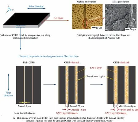
Fig.2 Laminar CFRP panel for compressive test along continuous fiber direction,optical micrograph between carbon fiber layer, and Scanning Electron Microscopy (SEM) photograph showing special Aramid pulp micro-fibers structure with fiber trunk twined by fine branches, thin epoxy layer in plain CFRP, CFRP with thin AP interlay, and CFRP with thick AP interlay.
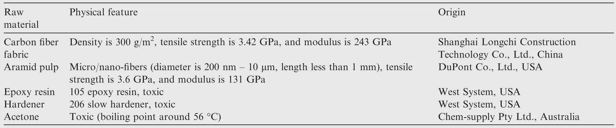
Raw material Physical feature Origin Density is 300 g/m2, tensile strength is 3.42 GPa, and modulus is 243 GPa Shanghai Longchi Construction Technology Co., Ltd., China Aramid pulp Micro/nano-fibers (diameter is 200 nm – 10 μm, length less than 1 mm), tensile strength is 3.6 GPa, and modulus is 131 GPa Carbon fiber fabric DuPont Co., Ltd., USA Epoxy resin 105 epoxy resin, toxic West System, USA Hardener 206 slow hardener, toxic West System, USA Acetone Toxic (boiling point around 56 °C) Chem-supply Pty Ltd., Australia
2.3.Compressive tests and other characterizations
Both compressive test and compressive test after impact illustrated in Fig.1 were performed using an Instron 5982 universal mechanical testing machine with a 100 kN load cell.The specimen size (width × length) of compressive test is 12 mm×140 mm.The specimen size of compressive test after impact is 100 mm × 150 mm.The tip of impact indenter is a spherical structure with a diameter of 16 mm.The displacement control mode with a rate of 1 mm/min was selected,and all tests were stopped after a sharp decrease in load was observed.
Fractured specimens were scanned by using X-Ray Micro-Computed Tomography(X-ray μCT)system(Versa 520,Zeiss,Pleasanton, CA, USA) for internal crack patterns.The test software Scout and Scan software (v11.1.5707.17179, Zeiss)was run at 30 kV and 67 μA to observe the post-peak crack and damage patterns.Morphology of AP embedded between carbon fiber plies on fracture surfaces was also scanned by SEM (Zeiss 1555VP-FESEM) with the high voltage of 5.0 kV.Moreover, the SAFE interlayer structures in CFRP with AP were observed via optical microscope (Olympus PMG3),images were collected with built-in Advanced Camera Software.
3.Experimental results and discussion
3.1.Uniaxial compressive strengths with AP interlays of different areal densities
The uniaxial compressive tests were conducted along the continuous carbon fiber direction using the in-house made CFRP composites interleaved with AP of 0,2,4,6,8 g/m2or with the AP interlays around 0, 6.7, 16.7, 24.4, 28.9 μm in thickness.Details on sample groups and dimensions,and number of tests are listed in Table 2,where the average maximum compressive failure loads Pmaxand average uniaxial compressive strengths are also summarized.
Typical uniaxial compressive load and displacement curves of CFRP composites with different AP interlays are shown in Fig.4(a).Only one among six tests from each group is shown here,and the selection is determined by whichever is the closest to the group average behavior.All six tests from CFRP composites with 0 and 6 g/m2AP micro-fibers are shown in Fig.4(b)to see the overall behaviors of the base plain and best interleaved CFRP composites.The apparent elastic moduli and compressive strengths of CFRP composites are shown in Figs.4(c) and (d), both pointing out CFRP composites with 6 g/m2AP has the optimum properties.The slight increase in overall thickness of CFRP composites due to the AP interlays has been included in the compressive strength and ‘‘effective”modulus calculations.The ‘‘effective” modulus and compressive strength were calculated by Eqs.(1) and (2) based on ASTM D6641:34
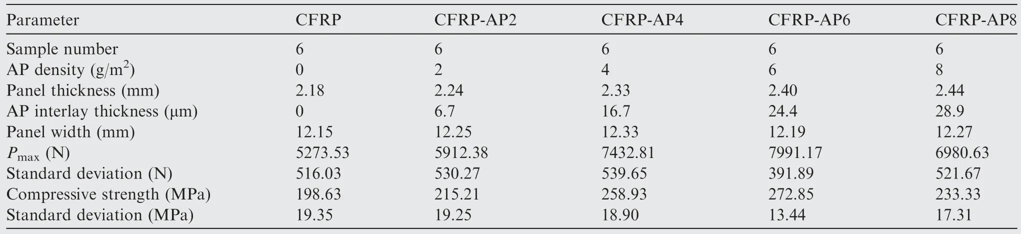
Parameter CFRP CFRP-AP2 CFRP-AP4 CFRP-AP6 CFRP-AP8 Sample number 6 6 6 6 6 AP density (g/m2) 0 2 4 6 8 Panel thickness (mm) 2.18 2.24 2.33 2.40 2.44 AP interlay thickness (μm) 0 6.7 16.7 24.4 28.9 Panel width (mm) 12.15 12.25 12.33 12.19 12.27 Pmax (N) 5273.53 5912.38 7432.81 7991.17 6980.63 Standard deviation (N) 516.03 530.27 539.65 391.89 521.67 Compressive strength (MPa) 198.63 215.21 258.93 272.85 233.33 Standard deviation (MPa) 19.35 19.25 18.90 13.44 17.31
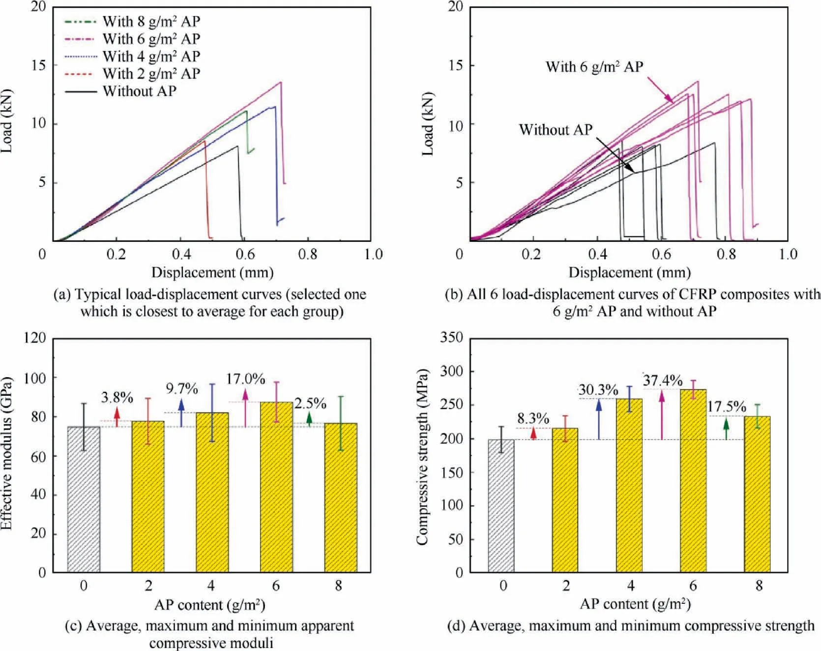
Fig.4 Uniaxial compressive test results of CFRP composites with different AP densities.
where Ecis only an ‘‘effective” compressive modulus as the machine cross-head displacement as in Fig.4 are used as the deformation of the CFRP samples, due to the movements of testing fixtures, Ecwill be much lower than the true modulus;εx1is the actual strain nearest lower end of strain range used;P1is the load at εx1; εx2is the actual strain nearest upper end of strain range used;P2is the load at εx2;w is the specimen gage width;h is specimen gage thickness;Fcuis the compressive strength measured along the continuous carbon fiber direction;Pfis the maximum load recorded in experiment.
3.2.Failure mechanisms of CFRP composites under uniaxial compression revealed from CT-scan
Under compressive loading along the continuous carbon fiber direction, CFRP composites are susceptible to delamination cracking between carbon fiber plies and micro-cracking along the carbon fibers.CT-scanning of CFRP interleaved with AP micro-fibers is probably the best way to reveal detailed internal failure modes while avoiding mechanical sectioning and polishing.
After uniaxial compression tests (passed the peak loads around 20% for all composites), one specimen from each group was used for SEM observations of fracture surfaces,and all remaining five specimens were CT-scanned for internal damage patterns.Fig.5(a) shows the typical CT-scan images of internal damage patterns in the plain CFRP composites(without AP), revealing the predominant vertical cracking and delamination modes along the compressive load and continuous carbon fiber direction.Thin AP-epoxy interlay enables to work on reducing delamination dominant mode of plain CFRP composites.The CFRP composites with 2 g/m2AP have demonstrated visible shear damage but with some cracking and delamination, while the almost perfect shear damage patterns of CFRP composites with 6 g/m2AP have been shown in Fig.5(c).On the contrary, a thick AP-epoxy interlayer(over 30 μm)will weaken the adhesive bonded properties by leading to resin-rich region, for an example of CFRP composites with 8 g/m2AP, they present internal cracking and delamination with less shear behavior in Fig.5(d).
Up to now,many studies have been carried out to improve interlay properties of laminar CFRP composites through interleaving methods.22The critical effect of interlayer thickness of interleaving on strength, modulus, fracture toughness was highlighted.Fig.6 shows several studies have investigated the influence of interlayer thickness on the strength of short fiber reinforced CFRP composites.Zhang et al.32used the Polyetherketone Cardo(PEK-C)nanofiber to reinforce CFRP composites with average interlayer thickness over 40 μm.Although the fracture toughness was improved, the flexural strength of reinforced composites was lower than that of the control group and decreased as the interlay thickness increased.Similarly, Ni et al.39concluded that the flexural strength was slightly improved only by laying one layer of Aramid veil(with an areal density of 16 g/m2),and then decreased as the number of interleaving layers increased.Then, Yuan et al.20attempted to toughen the CFRP composites via using ultra-thin SAFE with 13 μm in thickness,the flexural strength and the corresponding modulus after CAI have been enhanced by 16.9% and by 19.8% respectively.Then, Hu et al.21adopted thin AP-epoxy interleaving layer around 12 μm to toughen the flexural strength of CFRP.The combined results suggested that the flexural strength will not be affected if the interleaf thickness is less than 20 μm.In our recent study,4interleaved AP with 4 various interface density (2, 4, 6, 8 g/m2) has been proved to reinforce both transverse and longitudinal flexural strength of CFRP composites, and their ‘‘effective” modulus were also surprisingly improved in spite of around 15% as shown in Fig.7, noting their interlayer thicknesses are less than 30 μm.The ultra-thin AP interlay (or SAFE)with the interlayer thickness beyond 30 μm can further be proved to work on reinforcing compressive strength and modulus of CFRP composites.Again,it is the ultra-thin interleaving (<30 μm) instead of the thicker interleaving that can improve the interlay properties to strengthen the laminate CFRP.
3.3.Compressive strength after impact of CFRP interleaved with AP micro-fibers

Fig.7 Elastic modulus estimated from equivalent stress–strain curves under 3-P-B measurements,and corresponding average,maximum and minimum flexural moduli of CFRP composites with different AP micro-fiber densities.4
We have recently reported CAI tests of CFRP composites interleaved by short Aramid fibers with the impact energy ranging from 0–5.7 J20and 12.8 J.19Based on these previous observations, trail impacts with four different impact energy levels, 4.12, 12.35, 20.58, 32.93 J were performed for visual determination of the degree of low energy impact damage, as listed in Table 3.CFRP composites exhibit a small amount of carbon fiber splitting under the impact energy of 20.58 J and 32.93 J, but the structures still remain intact and no boundary damage can be found.Cracking and carbon fiber fracture(but without carbon fiber splitting)in the impact area are obvious for the impact energy of 12.35 J, so that the CAI tests are concentrated under this impact energy level for all sample groups.Table 4 lists the average CAI results of CFRP composites with different areal densities of AP interlays.
Fig.8 shows the CAI test details and measurements for the impact energy of 12.35 J.Typical uniaxial compressive load and displacement (machine cross-head) curves are exhibited in Fig.8(a), where the measured curves closest to the group average behaviors are compared.Again,the CFRP composites with 6 g/m2AP have the best CAI result, so that all six measurements are displayed in Fig.8(b) with those from the plain CFRP composites.The enhancement in CAI is close to 90%higher than the fiber reinforcing study28as in Fig.8(d).The‘‘effective” elastic modulus measurements in Fig.8(c) are for comparison only since the machine cross-head movements are also counted as the ‘‘displacement” measurements.The corresponding ‘‘effective” modulus and compressive strength after impact are calculated by Eqs.(3)and(4)based on ASTM D713735as

Parameter CFRP CFRP-AP2 CFRP-AP4 CFRP-AP6 CFRP-AP8 Sample number 6 6 6 6 6 CF ply number 10 10 10 10 10 AP density (g/m2) 0 2 4 6 8 Panel thickness (mm) 2.19 2.26 2.35 2.41 2.47 AP layer thickness (μm) 0 7.8 17.8 24.4 31.1 Impact energy (J) 4.12, 12.35, 20.58, 32.93
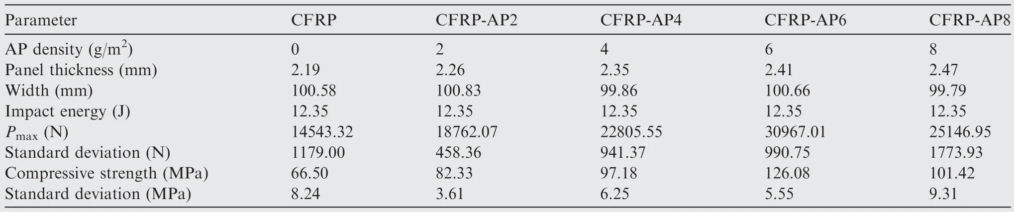
Parameter CFRP CFRP-AP2 CFRP-AP4 CFRP-AP6 CFRP-AP8 AP density (g/m2) 0 2 4 6 8 Panel thickness (mm) 2.19 2.26 2.35 2.41 2.47 Width (mm) 100.58 100.83 99.86 100.66 99.79 Impact energy (J) 12.35 12.35 12.35 12.35 12.35 Pmax (N) 14543.32 18762.07 22805.55 30967.01 25146.95 Standard deviation (N) 1179.00 458.36 941.37 990.75 1773.93 Compressive strength (MPa) 66.50 82.33 97.18 126.08 101.42 Standard deviation (MPa) 8.24 3.61 6.25 5.55 9.31
where ECAIis the‘‘effective”compressive modulus,GPa;FCAIis ultimate compressive residual strength, MPa; Pmaxis maximum force prior to failure, N; P1000and P3000are the applied forces corresponding to 1000 and 3000 micro-strain, N; ε1000and ε3000are recorded strain values closest to 1000 and 3000 micro-strain; A is cross-sectional area, A = hw, mm2.
3.4.Comparison of internal damage immediately after impact and CAI
The important role of AP interleaves in improving impact resistance and residual compressive strength can be demonstrated from X-ray μCT scans of damaged pattern after impact and CAI.Fig.9(a)exhibits the typical CT-scan images of plain CFRP composites (without AP) after impact, showing the internal cracking and delamination along the loading direction after impact with 12.35 J;Fig.10(a)displays the image of carbon fiber interlayer plane after impact demonstrating remarkable splitting cracking along the fiber direction, which may attribute to the weak interlayer adhesion property of pure epoxy.While the CFRP composites with 6 g/m2AP demonstrate small amounts of cracks and almost no delamination in Fig.9(b), and no splitting cracks at carbon fiber interlayer as shown in Fig.10(b) after impact with same energy as well.This indicates AP is conducive to preventing the delamination caused by impact and strengthening the impact resistance of CFRP, especially the weaker 90° direction of carbon fiber(or glass fiber direction).Moreover,it can be revealed by comparing the internal damage of plain CFRP composites and CFRP composites with 6 g/m2AP as in Fig.9(d), AP makes the failure mode change from ‘‘the dominated internal cracking and delamination” to ‘‘the dominated shear damage patterns with just a few delamination”, the different carbon fiber fracture cracks in Figs.10(c) and (b) also illustrate the dominated delamination of plain CFRP composites and dominated shear damage of CFRP composites with 6 g/m2AP.All the above mentioned explain why the CFRP composites with 6 g/m2AP have the optimal toughening effect for CAI.
3.5.SEM of damaged CFRP after compressive test
Fracture surfaces and morphologies of CFRP composites with 6 g/m2AP are displayed in Fig.11.The carbon fiber diameter is around 5 μm, and the diameter of AP micro-fibers can vary from around 0.2 μm to 10 μm.It can be observed that visibly pulled out AP fibers remain on the fracture surface of carbon fiber, and part of them still keep embedding into incompletely damaged adhesive region of residual resin and carbon fiber,illustrating how AP micro/nano-fibers promote the crackbridging behaviors, which also proves that AP micro/nanofibers have been pressed into the resin-rich regions between continuous carbon fibers, conducing to creating transitional region and even through-the-ply penetration.By toughening the epoxy matrix, reducing interlay crack and preventing delamination, those flexible AP micro/nano-fibers have contributed to manufacturing the‘‘high strength”CFRP composites.As suggested in Figs.2(c)and 6,thin interleaving layer less than 30 μm is an important condition,although 8 g/m2AP(about 28 μm)still has little effect on strengthening the CFRP,the reason is that the thicker interleaving layer (thicker than 30 μm) may cause the formation of resin-rich phenomenon to form the weak regions, which potentially leads to the easy crack generation and propagation.

Fig.9 X-ray μCT scans of damaged pattern.
4.Concluding remarks
This study shows that compressive strengths and elastic moduli of Carbon Fiber Reinforced Polymer (CFRP) composites have been noticeably improved by multiple ultra-thin interlays of un-bonded and non-woven Aramid Pulp (AP) micro/nanofibers.The benefits of ultra-thin AP interlays are evident before and after low energy impacts.This study has revealed that the ultra-thin AP interlays can be formed in situ, as demonstrated by the in-house pre-preg forming process.The penetration of AP micro-fibers into adjacent carbon fiber plies has been identified as an important mechanism for increasing the compressive strength and elastic modulus of CFRP.
The hierarchically-structured AP micro/nano-fibers with areal densities from 2 g/m2to 8 g/m2were applied to each ply surface.After compression molding, it was observed that an ultra-thin AP-epoxy interlayer less than 30 μm existed at the ply interfacial region of laminar CFRP.The interfacial region between carbon fiber plies can be separated into two distinct layers: (A) The mid-layer consisting of Short Aramid Fibers and Epoxy (SAFE) only, and (B) Two transitional or boundary layers due to the penetration of AP micro-fibers and random movements of free AP fiber ends into resin-rich areas at the ply interface.The middle SAFE layer increased the crack growth resistance in the ultra-thin epoxy adhesive joint between carbon fiber plies due to the fundamental variation from‘‘pure epoxy adhesive joint”to‘‘composite adhesive joint”.The transitional layer formed quasi-Z-directional fiber bridging across adjacent carbon fiber plies.
The results show that the interleaving layer thickness should be less than 30 μm to get the full benefits of the practical strengthening technique,which has been confirmed by both uniaxial compressive and 3-P-B tests.Flexible AP micro/nanofibers are certainly compared well with other micro/nanofibers.
Declaration of Competing Interest
The authors declare that they have no known competing financial interests or personal relationships that could have appeared to influence the work reported in this paper.
Acknowledgements
This work was supported financially by the National Natural Science Foundation of China (No.52102115) and the Fundamental Research Funds of Southwestern University of Science and Technology,China(No.20zx7141).The authors acknowledged the facilities, the scientific and technical assistance of Microscopy Australia at the Centre for Microscopy, Characterization & Analysis, the University of Western Australia.The authors would like to thank Shiyanjia Lab, China(http://www.shiyanjia.com) for SEM analysis.
 CHINESE JOURNAL OF AERONAUTICS2023年10期
- CHINESE JOURNAL OF AERONAUTICS的其它文章
- Experimental investigation of typical surface treatment effect on velocity fluctuations in turbulent flow around an airfoil
- Oscillation quenching and physical explanation on freeplay-based aeroelastic airfoil in transonic viscous flow
- Difference analysis in terahertz wave propagation in thermochemical nonequilibrium plasma sheath under different hypersonic vehicle shapes
- Flight control of a flying wing aircraft based on circulation control using synthetic jet actuators
- A parametric design method of nanosatellite close-range formation for on-orbit target inspection
- Bandgap formation and low-frequency structural vibration suppression for stiffened plate-type metastructure with general boundary conditions