
Hole surface strengthening mechanism and riveting fatigue life of CFRP/aluminum stacks in robotic rotary ultrasonic drilling
2023-11-10 02:16SongDONGWenheLIAOKanZHENGFengXUELianjunSUN
CHINESE JOURNAL OF AERONAUTICS 2023年10期
Song DONG, Wenhe LIAO, Kan ZHENG, Feng XUE, Lianjun SUN
School of Mechanical Engineering, Nanjing University of Science and Technology, Nanjing 210094, China
KEYWORDS
Abstract Carbon fiber reinforced plastic(CFRP)and aluminum stacks are widely used in aviation industry due to light weight and high performance.Millions of rivet holes need to be drilled on body materials, and more than 80% of fatigue cracks occur at the connection holes, so the damage and residual stress of hole surface have crucial effect on the riveting fatigue life of CFRP/aluminum stacks and the flight performance.Recently, robotic rotary ultrasonic drilling (RRUD) technology is a promising method to machine the stacks.However, the hole surface strengthening mechanism in RRUD and the service performance of the riveting joint are not verified.Thus,in this paper,the hole surface strengthening mechanism of RRUD for CFRP/aluminum stacks is investigated,a theoretical residual stress model is established, and the fatigue life experiment of riveted joints is conducted.Firstly, analysis on residual stress in RRUD is carried out with consideration of strengthening force and cutting temperature.Residual stress model is established based on the calculation of elastic stress, plastic stress and stress release.Validation experiment results show that ultrasonic vibration changes residual stress from tensile stress to compressive stress.At the same time,comparative damage analysis of CFRP hole exit and hole surface in robotic conventional drilling(RCD)and RRUD is presented.Finally,fatigue strength experiments of riveted joints are conducted for performance verification.Experimental results indicate that fatigue life of single-hole riveted joints is increased by 68% with ultrasonic vibration, and four-hole riveted joint arranged according to aerospace design standards is increased by more than 86%.
1.Introduction
In order to meet the demands of lightweight and structural strength,CFRP/aluminum stacks have been widely used in aircraft manufacturing including the F35 Lightning II,the Airbus A380 and the Boeing 787 Dreamliner.1–6During airframe manufacturing and assembly process, millions of rivet holes need to be drilled on body stacks materials.7–9According to the statistics, 70% of aircraft body fatigue failure originates from structural connections, and more than 80% of fatigue cracks occur at the connection holes.10So the quality of hole,especially the damage and residual stress of hole surfaces, is crucially important in the riveting fatigue life of CFRP/aluminum stacks and even the flight performance.Compared with manual hole drilling, robotic drilling has the advantages of high flexibility, high quality consistency and high phase accuracy.11–136-DOF serial robot equipped with drilling end effector offers operation flexibility, which is regarded as advanced option to accomplish aircraft component drilling.14–17.
In recent years, rotary ultrasonic drilling (RUD) technology, as a promising machining method, has been introduced to machine difficult-to-cut materials.18–22Compared with other machining methods,RUD enables many potentials,such as lower cutting force, less tool wear and smaller burr size.Yarar and Karabay23carried out RUD experiments on aluminum AA6061 with different heat treatments, and studied the effects of cutting parameters on machining.The results showed that ultrasonic vibration cutting can reduce cutting force and tool wear, and obtain better surface roughness at the same time.Li et al.24conducted an investigation on RUD of titanium alloys.Experimental results indicated that the thrust force, torque, cutting temperature, surface roughness, hole diameter deviation and burr height could be decreased by vibration assistance.Huang et al.25designed the RUD experiments of CFRP and systematically studied the tool wear behavior in machining.Compared with conventional machining, the introduction of ultrasonic vibration could reduce the average width of tool flank wear effectively,with a maximum reduction of 13.0%.Chang and Bone26compared burr size of aluminum which was machined by conventional drilling and RUD, and presented that RUD is superior in both burr height and width.Thus,Dong et al.27proposed a new method which combined RUD and robotic drilling.Their investigation realized the suppression of lateral chatter and the reduction of exit burr height by adopting ultrasonic vibration during robotic drilling, and the experimental results indicated that the stability lobe of robotic drilling was improved significantly and the burr height of aluminum plate was reduced by more than 40%.28.
However, the research of robotic ultrasonic drilling is mainly based on the problems of drilling quality, machining efficiency and so on, without considering the impact of this method on assembly performance.Investigation on damage and residual stress of hole surface during RRUD is still deficient so far.In recent years, high-performance manufacturing has become the international research frontier.Damage and residual stress have crucial effect on the riveting fatigue life of CFRP/aluminum stacks.Previous studies focused on the suppression effect of ultrasonic vibration on the robotic drilling chatter and exit burr, but the influence of ultrasonic field energy on the residual stress formation, drilling damage and fatigue performance has not been clarified.Therefore,in order to improve the investigation on riveting fatigue life,this paper firstly presents a study on the hole surface strengthening mechanism and riveting fatigue life of CFRP /aluminum stacks in RRUD.It is organized in five sections.Following this introduction section, the procedure of developing the theoretical model for residual stress is shown in Section 2.Hole surface damage of CFRP drilling is analyzed in Section 3.In Section 4,fatigue life experiments of riveted joints are conducted to verify the effect of RRUD.Conclusions are drawn in Section 5.
2.Residual stress analysis of RRUD
2.1.Strengthening force
2.1.1.Strengthening force from average drilling force
In RRUD, the factors that influence the thrust force generation can be divided into two groups.One group consists of certain factors,including mechanical properties of material,uncut chip thickness and tool geometric sizes.The other includes uncertain factors, including the stability of RRUD system(Fig.1) and the cutting temperature.
From previous study,28thrust force Fthcan be expressed as
where Fth0represents the certain component of thrust force;K is the correction parameter denoting the uncertain component;n is the spindle speed; vfis the feed rate; A is the amplitude of ultrasonic vibration;is the thrust force on cutting edge;is the thrust force on chisel edge; d is the diameter of drill bit; d’ is the diameter of chisel edge; τAland σAlare the shear and yield stress of aluminum;ψ is the chisel angle;ω is the half chisel thickness; r is the distance to the tool center; E is the elastic modulus of aluminum; vAlis the Poisson ratio of aluminum; kchis the coefficient of chisel edge; γfis the angle between feeding direction and the force on chisel edge; γwis the wedge angle.
In Eq.(1), acis the axial uncut chip thickness and can be calculated as
where T is the period of rotational angle, T=; F is the frequency of ultrasonic vibration.
As shown in Fig.2, aluminum hole surface is subjected to high-frequency extrusion by twist drill in RRUD.This compression is similar to the effect of strengthening process,which can change the internal stress on surface.Extrusion force perpendicular to the hole surface shown in Fig.2(a) is defined as the strengthening force.
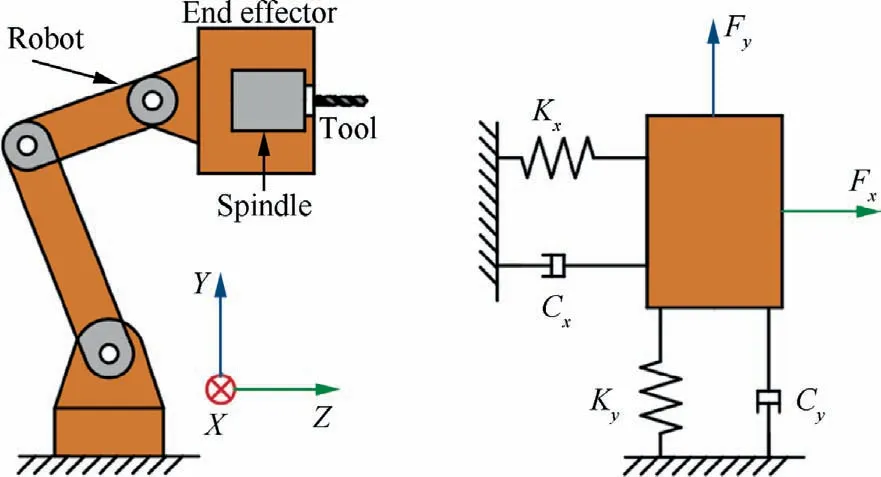
Fig.1 Structure and dynamic model of RRUD system.
During RRUD, total strengthening force is generated by dynamic impact force and average cutting force, and it can be expressed as
where Fqis the total strengthening force; Fqdand Fqsare the strengthening force formed by dynamic impact force and average cutting force, respectively.According to the force analysis in Fig.2(b),the total force FRcan be decomposed into Faand Fqin the axial and radial directions, and into Ffand Fnin the tangential and vertically tangential directions.By the meaning of angle relationship in the diagram,Fqsgenerated by the average cutting force can be calculated as
In Eq (2), Fasis the average thrust force on cutting edge,and csand dsare the upper and lower limits of the axial force integral in the fillet part of the cutting tool,respectively.βcand γcare the reference angles shown in Fig.2(b),which can be calculated as
where μ is the friction coefficient between tool and workpiece,u is the thickness of extrusion layer,and rqis the fillet radius of the twist drill.
2.1.2.Strengthening force generated by vibration impact
In the formation of hole surface strengthening force,the ultrasonic vibration effect is manifested by the introduction of instantaneous dynamic impact.Strengthening force by dynamic impact Fqdshould be analyzed with kinematics of RRUD.The displacement equation,axial velocity and acceleration at any point of cutting edge in RRUD are expressed as
According to Newton’s second law of motion,the dynamic force of cutting tool fillet under high frequency vibration can be expressed as
In Eq.(8),m=4/3ρπ (rq)3,which is the mass at tool fillet,and ρ is the density of tool material; Fadmaxis the maximum dynamic impact force.And the strengthening force by Fqddynamic impact can be obtained from the geometric relationship shown in Fig.2 (b):
2.2.Cutting temperature
During drilling,the work done by axial force is the fundamental cause of cutting temperature.29,30The linear velocity of the tool rotation is perpendicular to the axial force direction, so the linear velocity has no effect on the axial force work and can be ignored in this model.The axial velocity based on kinematics analysis of RRUD can be expressed as
The power of the work done by the axial force generating heat can be expressed as
Therefore, the heat flux q can be calculated by
where Fthis the thrust force of aluminum in RRUD; Vais the axial velocity; η1is the proportionality factor of heat transfer.In this study, the cutting temperature is defined as the maximum temperature in drilling area.It is assumed that the heat distribution ratio of the workpiece and the tool is proportional to their thermal conductivity.Thus,η1=λ1/(λ1+λ2),where λ1and λ2are the thermal conductivity of aluminum and carbide tool.P is the thermal work equivalent, P = 4.1840 J/cal; S is the heat source area which can be expressed as
According to the temperature field theory of continuous infinite heat source,31the maximum temperature of RRUD can be expressed as
where q is the heat flux; λ1is the thermal conductivity of aluminum workpiece; β1is the thermal diffusivity of the workpiece, β1= λ1/cρAl,c is the specific heat capacity of the workpiece material, and ρAlis the density of the workpiece material; t1is the temperature rise time.
Substitute Eq.(12)into Eq.(14),and the expression of temperature prediction model for RRUD of aluminum is shown as
Substitute Eq.(1) and Eq.(13) into Eq.(15), and the relationship among cutting parameters, vibration parameters and cutting temperature can be expressed as
2.3.Residual stress model in RRUD
2.3.1.Elastic stress
In RRUD,the contact between the tool fillet and the surface of hole surface is a special form of Hertz contact between two spheres,that is,one sphere is a flat plate.Deformation characteristics of Hertz contact are shown in Fig.3.Radial displacement of two elastic spheres when they impact and extrude against each other can be calculated as
where U1(l) and U2(l) are the displacements of ball 1 in ball 2 and ball 2 in ball 1,respectively;ξ is the total displacement on the connecting line, ξ = d1+ d2; leis the equivalent contact radius, and can be expressed as
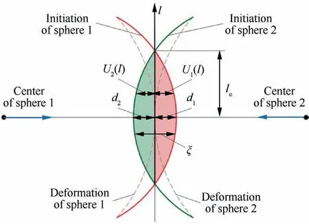
Fig.3 Schematic diagram of deformation characteristics of two spheres in Hertz contact.
where l1and l2are the radius of ball 1 and ball 2,respectively.
When ball 2 is replaced by a flat plate, the radius l2is infinite.Assuming that the carbide tool is rigid, the displacement U2(l)of ball 2 on ball 1 at this point is close to 0.Therefore,the tool fillet and the extrusion displacement of hole surface can be expressed as
According to Hertz contact theory,32the pressure distribution in contact area and the relationship between displacement and pressure can be expressed as follows:
where P(l)is the contact pressure in the direction of l;Pmis the maximum pressure at the center-connecting line;lmis the maximum contact radius;Eeis the equivalent elastic modulus,and can be obtained by
where E1and E2are the elastic modulus of the two contacts,and ν1and ν2are the Poisson ratio of two contacts.
According to the research results of Teimouri and Amini,33the relationship among the maximum pressure Pm, the maximum contact radius lmand the hole surface strengthening force Fqcan be expressed as
Based on the elastic stress theory of Hertz contact,the elastic stress expression along the hole surface direction is
where σea, σetand σeqare the elastic stresses in the axial, tangential and hole surface thickness directions of the tool,respectively;νAlis the elastic modulus of aluminum material;s is the thickness value from the hole surface.Von Mises yield rule is used to analyze the internal stress of the material, and equivalent von Mises elastic stress and strain are described as follows:
2.3.2.Plastic stress
Based on the theory of linear relationship between elastic strain and elastic–plastic strain,34elastic–plastic strain can be expressed as
where c1is the ratio of plastic deformation to elastic deformation.It can be expressed as
According to the Hertz contact principle, the elastic deformation diameter decan be obtained by
At the same time, the plastic deformation diameter can be calculated by
where Sbis the ultimate stress of aluminum material.
Introduction of ultrasonic vibration makes tool and hole surface press repeatedly at high frequency.And the hole surface material shows an extremely high strain rate, which can be calculated as
The vibration frequency of ultrasonic machining is usually above 20000 Hz.According to Eq.(32),the material strain rate caused by ultrasonic impact is above 6.28×10⁴s-1.When the strain rate is above 104,Johnson-Cook(J-C)model is the most suitable method for calculating the flow stress on the workpiece surface.35
where A, B, C, m and n are the material physical constants of the J-C model.A is the initial yield stress of the workpiece material; B is the hardening constant; C is the strain rate constant;m is the thermal soft index;n is the hardening index;θ is the cutting temperature of RRUD;Tris room temperature;Tmis the melting point of aluminum.
2.3.3.Stress release and equalization
As shown in Fig.4, stress–strain curve (red curve) of metallic materials can be simplified to multi-segment lines.The ultimate elastic stress based on isotropic hardening theory can be expressed as
In order to facilitate the calculation of residual stress, this study makes the following assumptions: (1) Deformation of hole surface is small; (2) Unloading process is elastic until the reverse yielding begins; (3) Static pressure does not cause plastic deformation.Based on the above assumptions, preresidual stress can be calculated by elastic stress and plastic deviatoric stress:
For isotropic materials, the above expression can be expressed as36
According to the material model shown in Fig.4, reverse yielding and hardening occur when σe≥2σp.At this point,the pre-residual stress can be calculated as
Based on the findings of Teimouri33and Li et al.34, the residual stress type applied on the surface is a complete plane stress when the whole hole surface is subjected to multiple impacts.That is, the above stress is only applied to the depth of material (in the direction of hole surface thickness), and there is no change in the axial and tangential direction of tool.This indicates that the strain value in the plane is zero,and the strain-dependent nonzero value only occurs in the direction of the hole surface thickness.Therefore, the only possible preresidual stress and strain boundary conditions are
From Eq.(37)and Eq.(38), it is clear that the pre-residual stresses and strains do not satisfy the above equilibrium boundary conditions, and stress relaxation must be generated.The corresponding relaxationandcan be obtained according to Hooke’s law:
Therefore,the surface residual stress model of robot rotary ultrasonic drilling hole surface can be expressed as
From the above analysis on residual stress theoretical model of hole surface, it can be seen that the ultrasonic vibration enhances the extrusion effect of tool on hole surface.Under the extrusion effect on hole surface,plastic deformation occurs in the machining area.After the unloading of external load, the material in the plastic deformation area cannot be recovered.The grain dislocation and slip are generated inside the workpiece.In addition, by Johnson-Cook continuity model, the plastic stress is greatly affected by the cutting temperature during dry drilling, and the uneven temperature field distribution is formed in the surface and interior of the hole surface material.The volume expansion trend of surface material is restricted by internal material, which generates residual stress on the surface.
2.4.Validation experiment of residual stress model in RRUD
2.4.1.Experimental setup
Drilling experiments are performed on the robotic machining system shown in Fig.5.Laser vibrometer (Polytec OFV-5000)is used to calibrate the ultrasonic amplitude of tool tip.The stacks are composed of CFRP (CCF300) and aluminum(Al7075).Material physical constants of J-C model for aluminum are shown in Table 1.And the thermal conductivity λ1is 173 W/(m∙K), heat capacity c is 0.96 J/(g∙K), and room temperature is 20°C.Mechanical properties of CFRP and aluminum materials are shown in Table 2 and Table 3 respectively.The tool used in the experiment is a carbide twist drill with a diameter of 4.5 mm.Tool geometric parameters are shown in Table 4.Both single factor experiments and orthogonal experiments are carried out to verify the accuracy of residual stress model.Experimental parameters and levels are shown in Table 5 and Table 6.Residual stress on aluminum hole surface is measured by a X-ray stress tester (X-350A).Laser microscope(KEYENCE VK-X150)and field emission scanning electron microscope(SEM Quant 250FEG)are used to observe the hole surface damage and outlet damage of CFRP.
2.4.2.Experimental results and analysis
Measurement results of residual stress under RRUD and RCD are shown in Fig.6.It can be seen that residual stresses at the aluminum hole surface in RRUD are negative, and the intakeof ultrasonic vibration energy causes residual stresses to change from tensile stresses (positive values) to compressive stresses (negative values).
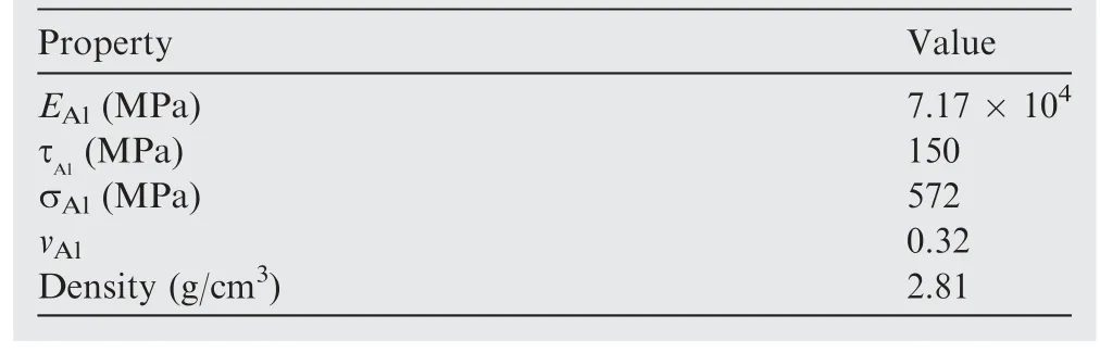
Property Value EAl (MPa) 7.17 × 10⁴ τAl (MPa) 150 σAl (MPa) 572 vAl 0.32 Density (g/cm3) 2.81
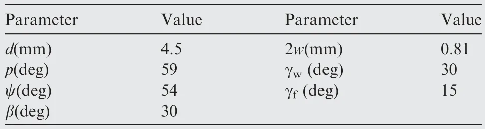
Parameter Value Parameter Value d(mm) 4.5 2w(mm) 0.81 p(deg) 59 γw (deg) 30 ψ(deg) 54 γf (deg) 15 β(deg) 30

Fig.5 Robotic rotary ultrasonic drilling system.
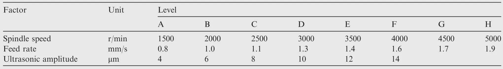
Factor Unit Level A B C D E F G H Spindle speed r/min 1500 2000 2500 3000 3500 4000 4500 5000 Feed rate mm/s 0.8 1.0 1.1 1.3 1.4 1.6 1.7 1.9 Ultrasonic amplitude μm 4 6 8 10 12 14
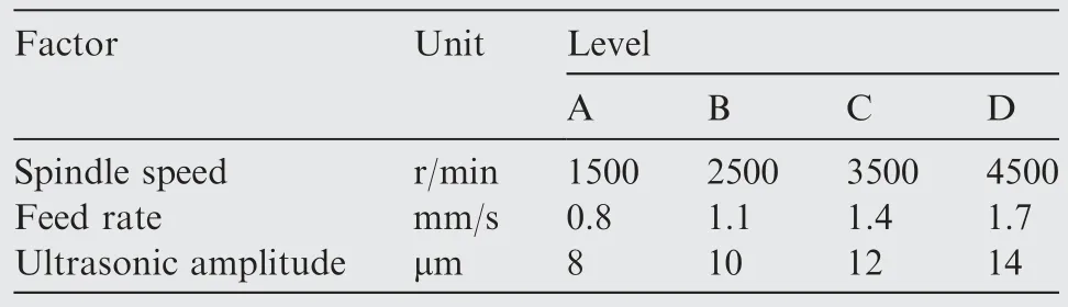
Factor Unit Level A B C D Spindle speed r/min 1500 2500 3500 4500 Feed rate mm/s 0.8 1.1 1.4 1.7 Ultrasonic amplitude μm 8 10 12 14
Fig.6(a) shows the variation of residual stress with the spindle speed.It can be found that the residual stresses tend to decrease with the increase of spindle speed for both machining methods, and the residual stresses decrease more when the speed increases from 1500 r/min to 3500 r/min for RCD.Therefore, RCD at low spindle speed has a greater effect on the residual stresses.In contrast, the curve change is relatively flat in RRUD, and the residual stresses are relatively weakly influenced by the spindle speed.
The effect of feed rate on the residual stress is shown in Fig.6(b).Residual stresses on the hole surface increase when the feed rate raises, and this trend is observed in both RCD and RRUD.This is due to the fact that an increase in feed rate indicates increment in feed per revolution and material removal per unit time, eventually causing an increase in the average cutting force.The raise in average cutting force contributes to the increase in residual stress.
Fig.6(c) shows the effect of ultrasonic amplitude on the residual stress during RRUD.Residual stress tends to enhance significantly with the increasing amplitude.When the ultrasonic amplitude raises from 4 μm to 14 μm, the residual stress value increases from 39.4 MPa to 107.6 MPa,with an augmentation of 173.1%.This is because there is a positive correlation between the ultrasonic amplitude and the instantaneous vibration impact force.
Substituting the RRUD parameters and material properties into theoretical model, the predictive values of residual stress can be obtained.The relative error of residual stress prediction is shown in Fig.7.The relative error of theoretical prediction ranges from 1.6% to 12.1%.Only one group has a prediction error of more than 10%, and rest of groups are within the acceptable range, with an average relative error of only 6.9%.Therefore,the results of experiments verified the validity and correctness of residual stress theoretical model.The model has a high prediction accuracy and can be used for prediction of residual stresses in RRUD.
3.Drilling damage of CFRP in RRUD
3.1.Comparison of CFRP hole surface damage
As shown in Fig.8(a), severe defects of hole surface are observed in RCD, with a large depth of pits.The deepest pit is magnified(×1000)using SEM as shown in Fig.9(a).A large number of microscopic defects such as exposed fibers, fiber pull-out and micro-cracks exist in the pit.These defects limit the load-bearing capacity of hole surface greatly.In contrast,the surface of CFRP is relatively flat in RRUD.The same SEM magnification (×250) observation of hole surface is shown in Fig.8(b), which has only mild scratching, so the quality of hole surface is significantly improved.From Fig.8(d),we can see that, at spindle speed of 5000 r/min in RRUD,CFRP hole surface defects are minimal and the hole surface quality is the best.

Fig.6 Comparison curve of residual stresses at hole surface by two processing methods.
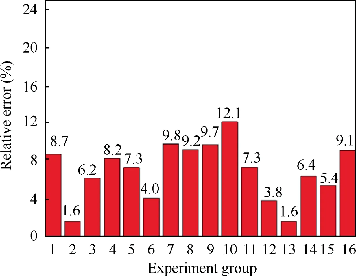
Fig.7 Prediction accuracy of theoretical model for residual stresses.
Effects of ultrasonic vibration and feed speed on the defects are shown in Fig.10.Overall analysis of Fig.10(a)-(d) shows that RRUD decreases hole surface defects when the feed speed is varied.CFRP defects under both RCD and RRUD tend to deteriorate as the feed rate increases.SEM images (×1000) of the deepest position of the pit are shown in Fig.11(a)and(b),respectively.The pit of the defect in RCD is relatively deeper.Fiber fracture disorder, fiber voids and crack clustering in the pit are obvious,which will have a great impact on the riveting strength of stacks inevitably.In RRUD, the CFRP hole surface also shows certain defects.Fiber exposure phenomenon is more significant, but depth of the pit and the defect range are significantly smaller than those in RCD.These indicate that the effect of ultrasonic vibration can still inhibit the formation of defects in the robotic drilling at higher feed rate.
Effect of ultrasonic amplitude on hole surface defects in RRUD is shown in Fig.12.Surface defects improve gradually as the ultrasonic amplitude increases from 8 μm to 12 μm.When ultrasonic amplitude is 8 μm, hole surface defects show a shallow scratch in depth.When the amplitude is raised to 10 μm, the area of scratch damage is rapidly reduced, and flat surface can be obtained when it is increased to 12 μm.However, when the ultrasonic amplitude is 14 μm, the surface defects of the hole surface appear again.The SEM magnification observation is shown in Fig.13.Defects are in the form of matrix spalling and fiber exposure, and deep pits disappear.
3.2.Exit damage in RRUD
CFRP drilling exit is prone to defect in the form of edge chipping and delamination, as shown in Fig.14.As can be seen in Fig.14(c), the depth of the edge crack is large, reaching more than 135 μm.Effect of ultrasonic vibration and spindle speed on the exit defect of robotic drilling is shown in Fig.15.A comprehensive comparison shows that RRUD decreases edge chipping and delamination, and obtains a relatively complete edge.In addition, with the gradual increase of the spindle speed, exit defects show a trend of improvement by both machining methods.This is because the thrust force of drilling decreases as the feed per tooth reduces.As a result, the tool force on the uncut layer at the exit is reduced and the drilling exit defect is improved.
4.Fatigue life of riveted joints in RRUD
4.1.Optimization of RRUD parameters
In this section,optimization of RRUD parameters for CFRP/aluminums stacks is carried out.First,objective function is set according to the material removal efficiency and machining quality requirements.Then, the constraint conditions are determined according to the performance requirements of end-effector and ultrasonic machining device.The volume of material removed per unit time is usually used as the main indicator to characterize the cutting efficiency, which can be expressed as
where Q is the material removal rate, which is the material removal volume in unit time; π is a constant; R is the drilling radius;n is the spindle speed;fris the feed per revolution.Penalty function method of particle swarm algorithm is chosen to transform this optimization mathematical model into an unconstrained problem.With the penalty function method,incorporating the constraints into the objective function yields:

Fig.8 Effect of ultrasonic vibration and spindle speed on the shape of defects (Feed rate: 1.2 mm/s).
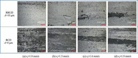
Fig.10 Effect of ultrasonic vibration and feed rate on shape of defects.
Particle swarm algorithm is used to solve this optimization mathematical model.The initial particle population is generated in a random way.The number of particles is set as 200 where each particle has four dimensions.The acceleration constants are all defined as 2 and the maximum number of iterations is set as 300.The optimization results are shown in Table 7.The frequency of the ultrasonic machining system is determined by the system structure and the design frequency is 20 kHz.
4.2.Fatigue life experiments
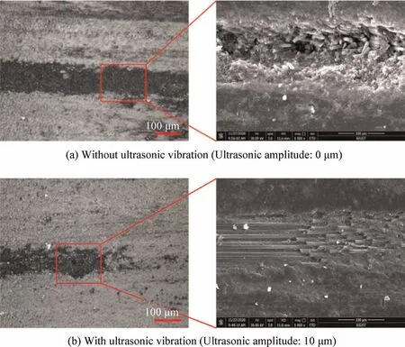
Fig.11 SEM inspection diagram of local amplification of CFRP hole surface defects (spindle speed: 3500 r/min, feed rate: 1.9 mm/s).
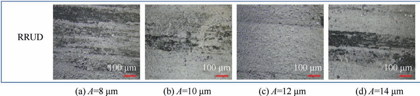
Fig.12 Effect of ultrasonic vibration amplitude on hole surface defects.

Fig.13 SEM inspection map of local amplification of CFRP hole surface defects (Ultrasonic amplitude: 14 μm).
Single- and four-hole riveted joints of fatigue test workpiece are shown in Fig.16(a).The rivets are made from aluminum 2117-T4 with 5 mm diameter bar and 12 mm length, and are drilled using 5.1 mm diameter tool in accordance with the standard riveting technology.In order to avoid the influence of riveting process on fatigue life, the riveting process is completed with the assistance of aviation industry Jiangxi Hongdu Aviation Industry Group Co., Ltd., and the riveting process ensures the consistency of riveting force of each workpiece.Furthermore,the addition of the balance piece makes the load direction perpendicular to the rivet axial direction, which makes the working condition closer to the actual flight state of the aircraft.After riveting, the clamping of experimental parts and the site of fatigue test are shown in Fig.17.A universal fatigue test machine(LFV100kN)is selected for the fatigue test.The maximum static load is 100 kN, the maximum dynamic load is 50 kN,and the maximum frequency is 250 Hz.

Fig.14 Typical shape of exit defect of CFRP drilling.
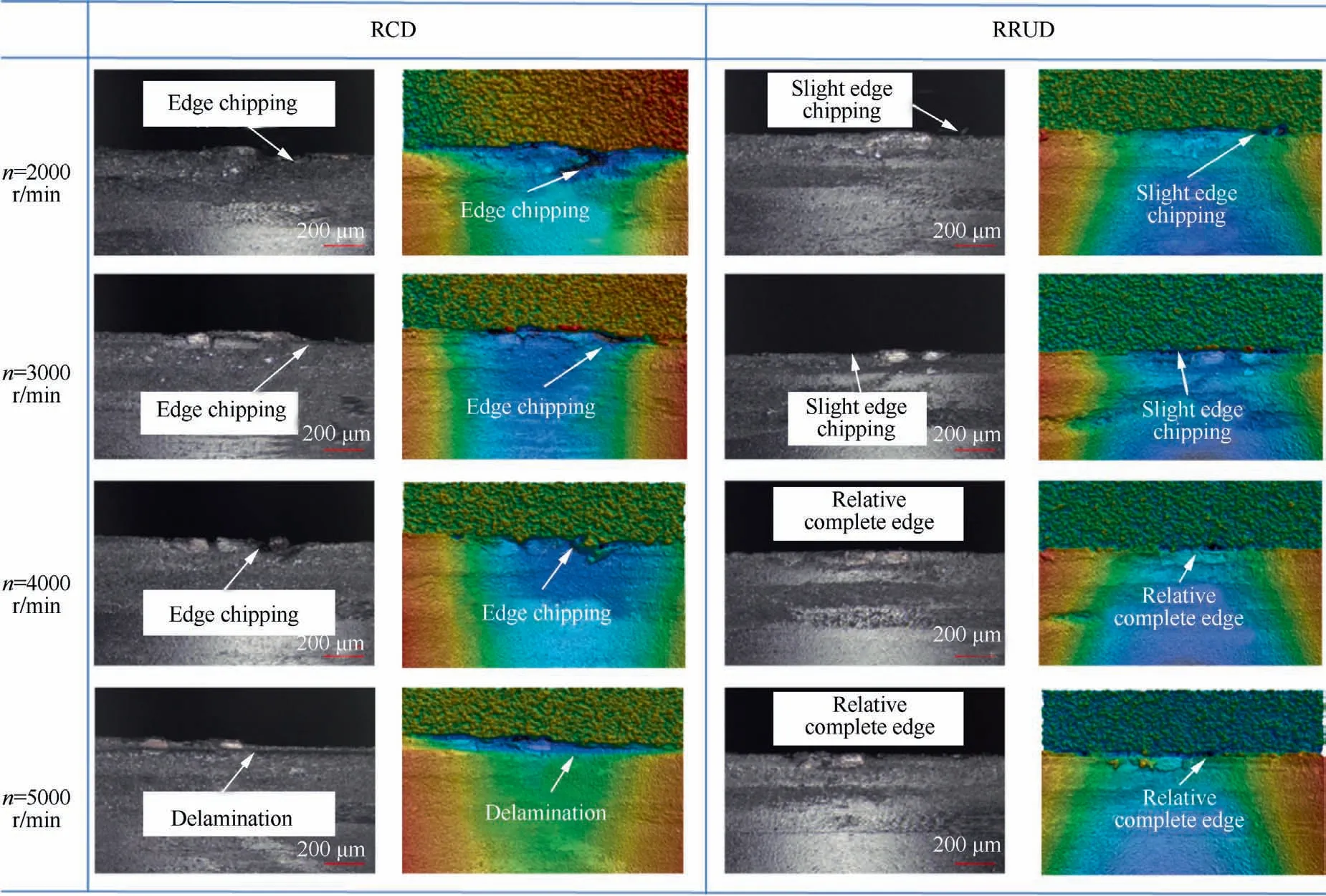
Fig.15 Effect of ultrasonic vibration and spindle speed on exit defects.
Tensile fatigue tests of single-hole and four-hole riveted stacks are all carried out at room temperature.80% of static tensile ultimate strength is selected as the maximum load stress.The stress ratio and tensile frequency are set as 0.1and 50 Hz respectively.When the displacement between plates of stacks exceeds 5% of the hole diameter, the joint is judged to fail.Each group of fatigue tests is repeated 20 times and any large deviation is averaged out to avoid chance error effect.

Parameter Value Number of iterations 300 Spindle speed (r/min) 4489.99 Feed rate (mm/s) 1.63 Ultrasonic amplitude (μm) 10.43

Fig.16 Structure of fatigue test workpiece.
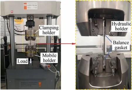
Fig.17 Clamping of test pieces and fatigue test site.
4.2.1.Static tensile test results
The static tensile experiment of riveted joints is firstly carried out to lay the foundation for the tensile fatigue test.Ten groups of riveted joints are tested with and without ultrasonic robotic drilling, and those groups with abnormal results are removed.The load–displacement curves for single-hole riveted joints with both RRUD and RCD are shown in Fig.18.
At the initial stage, when the displacement is less than 0.05 mm,there is an approximately linear relationship between load and displacement.In addition to the elastic deformation of the assembly under tensile load, friction also exists at this point to resist shear load.This stage is mainly due to the gap fit between the nail hole and the rivet, and tensile load is mainly used to overcome the friction between the plates.There is no significant effect of process methods on the load–displacement curve at this stage, as the rivet does not exert an extrusion force on the hole surface.When the load exceeds the elastic limit σe, the curve enters the stable load-bearing phase.Compared with RCD, better quality of hole surface and residual compressive stress are obtained in RRUD processing, which inhibits crack initiation and expansion effectively, resulting in a higher load carrying capacity.The final stage of the curve is the damage and destruction stage of the material.By comparing the ultimate load σb, the static load limit of the riveted joint is increased by more than 12% via the action of ultrasonic vibration.
4.2.2.Fatigue test results
Average fatigue life of single-hole riveted CFRP/aluminum stacks processed by RCD is 731,237 cycles, compared with 1,231,275 cycles processed by RRUD.Fatigue life of singlehole riveted joints drilled by RRUD is increased by more than 68%.Average fatigue life of four-hole riveted stacks machined by RRUD and RCD are 713,627 cycles and 381,787 cycles respectively.The introduction of ultrasonic vibration makes an increase of more than 86% for the four-hole riveted joint.In addition, the fatigue life of the four-hole riveted joint is lower than that of single-hole riveted joint for both RRUD and RCD.In RCD, the fatigue life of the four-hole riveted joint is reduced by 47.8% compared with the single-hole riveted joint.The reduction in RRUD is 42.0%.As the number of holes raises,the likelihood of hole surface damage increases.Crack sprouting and fatigue damage in any riveted hole have an effect on the fatigue life of the overall joint.Therefore,fatigue life experiments effectively verify the effect of ultrasonic vibration on the drilling quality improvement of CFRP/aluminum stacks.

Fig.18 Load-displacement curves of riveted joints.
4.3.Analysis of fatigue damage morphology
Laser microscopy is used to analyze the damage to the aluminum surface of the laminated joint after 380,000 cycles of tensile fatigue, and the results are shown in Fig.19.After tensile fatigue, the hole surfaces of the riveted joints show increased damage and cracking on the aluminum surface under repeated compression of the rivets.By comparing the results of surface inspection between RCD and RRUD,ultrasonic vibration effectively inhibits the expansion of damage and crack initiation on the aluminum hole surface.The degree of damage is significantly less than that of RCD.
The reasons for the above phenomenon can be specifically analyzed from the following aspects: From the analysis of the reinforcement effect in RRUD,residual stresses in the hole surface are transformed from tensile stresses to compressive stresses, which effectively increase the load-bearing capacity of the hole surface and extend the fatigue life of stacks.In addition, from the analysis of the stability of RRUD, it is found that the machining state is stable and the hole diameter deviation is significantly improved.27Meantime, from the analysis of the exit burr of aluminum in RRUD, the effect of ultrasonic vibration on the reduction of the burr height is significant.The improvement of hole diameter and exit burr size has an important role for improvement of fatigue life.Combined with the inhibition of microscopic cracking by residual compressive stress,the superposition of the two effects effectively extends the fatigue life of the riveted joint.
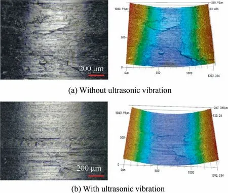
Fig.19 Surface profile of aluminum hole after 380,000 cycles of tensile fatigue.
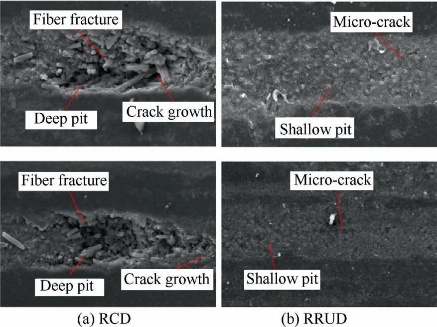
Fig.20 Surface morphology of CFRP hole after 380,000 cycles of tensile fatigue (×1000).
CFRP hole surface damage after 380,000 cycles of tensile fatigue is observed as shown in Fig.20.The surface of CFRP hole exhibits severe damage under repeated compression by the rivet.By comparing the CFRP hole surface morphology of RRUD and RCD, it can be seen that the hole surface of RCD shows deep pits, cracks and fiber breaks after 380,000 cycles of tensile fatigue and the riveted joint reaches failure criteria.At the same number of fatigue cycles,CFRP hole surface with RRUD only shows micro-cracks and shallow pits, which is a significant improvement.
5.Conclusions
This study proposes the strengthening mechanism of residual stress and surface damage during RRUD of CFRP/aluminum stacks.Meantime, tensile fatigue experiment for riveted joints of CFRP/aluminum stacks is carried out to verify the improvement effect on the service performance.The main conclusions are drawn as follows:
(1) A theoretical model of residual stresses with consideration of the combined effects of drilling temperature and thrust force is established.Residual compressive stresses are effectively formed by RRUD.Effect of ultrasonic amplitude on the residual compressive stresses is significant.When the ultrasonic amplitude is increased from 4 μm to 14 μm,the increase of the residual stress reaches 173.1%.
(2) CFRP damages of hole surface and hole exit are significantly improved under the action of ultrasonic vibration.As the feed rate increases, the CFRP hole surface defects tend to deteriorate for both RCD and RRUD.As the spindle speed increases, the hole surface quality gradually improves.
(3) Compared with RCD,the hole surface of RRUD shows a higher static load carrying capacity.The fatigue life of single-hole riveted joints is increased by 68%, and the fatigue life of four-hole riveted joints arranged according to aerospace design standards is increased by more than 86%.
Declaration of Competing Interest
The authors declare that they have no known competing financial interests or personal relationships that could have appeared to influence the work reported in this paper.
Acknowledgements
This study was co-supported by the the Project on the Technological Leading Talent Teams Led by Frontiers Science Center for Complex Equipment System Dynamics (No.FSCCESD220401) and the Jiangsu Funding Program for Excellent Postdoctoral Talent (No.2022ZB264).
 CHINESE JOURNAL OF AERONAUTICS2023年10期
- CHINESE JOURNAL OF AERONAUTICS的其它文章
- Experimental investigation of typical surface treatment effect on velocity fluctuations in turbulent flow around an airfoil
- Oscillation quenching and physical explanation on freeplay-based aeroelastic airfoil in transonic viscous flow
- Difference analysis in terahertz wave propagation in thermochemical nonequilibrium plasma sheath under different hypersonic vehicle shapes
- Flight control of a flying wing aircraft based on circulation control using synthetic jet actuators
- A parametric design method of nanosatellite close-range formation for on-orbit target inspection
- Bandgap formation and low-frequency structural vibration suppression for stiffened plate-type metastructure with general boundary conditions